

Europlex SigNET 200, SigNET 300 User Manual

SigNET 200/300 User Guide
SigNET 200/300
User Guide
E-LAB-1543 1
SigNET 200/300 User Guide
Warning: While this system is an advanced design integrated security system, it does not offer guaranteed protection against
burglary, fire or other emergency. Any alarm system, whether commercial or domestic, is subject to compromise or failure to
warn for a variety of reasons.
Therefore, good installation practices, thorough testing, and regular maintenance by the installation company and frequent
testing by the user are essential to ensure continuous satisfactory operation of the system. It is recommended that the
installation company offer a maintenance program and instruct the user with the correct procedure for use and testing of the
system.
COPYRIGHT NOTICE
Copyright © 2007 Europlex Technologies Ltd (hereby referred to as Europlex). All rights reserved. No part of this publication
may be reproduced, transmitted, stored in a retrieval system, or translated into any language or computer language in any
form or by any means electronic, mechanical, magnetic, optical, chemical, manual, or otherwise without the prior written
permission of Europlex.
Disclaimer: Europlex make no representations or warranties with respect to the contents hereof and specifically disclaim any
implied warranties of merchantability or fitness for any particular purpose. Further Europlex reserve the right to revise this
publication and to make changes from time to time in the contents hereof without the obligation of Europlex to notify any
person of any such revision.
All products or services mentioned in this manual are covered by the trademarks, service marks, or product names as
designated by the companies who market those products.
E-LAB-1543 SigNET 200/300 User Guide, Issue 02, December 2007
When changing or installing expanders on the SigNET 200/300 system always ensure that all
anti-static precautions are adhered to while handling connectors, wires, terminals and PCBs.
Europlex Technologies [IRL] Ltd.
Clonshaugh Business and Technology Park,
Clonshaugh,
Dublin 17,
Ireland.
Tel: +353 (0) 1 2500500
Fax: +353 (0) 1 2500592
2 E-LAB-1543
Company Web Site address: www.europlex.ie
E-Mail: sales@europlex.ie
Technical Support: tech@europlex.ie
Europlex Technologies (UK) Limited
Innovation Centre,
Cranfield University Technology Park,
University Way, Cranfield,
Bedfordshire, MK43 0BT,
United Kingdom.
Tel. +44 (0) 8700 600 140
Fax. +44 (0) 8453 307 240

SigNET 200/300 User Guide
Table of Contents
1. INTRODUCING THE SIGNET 200/300 SYSTEM ............................................................................................................. 4
2. USING THE KEYPAD ............................................................................................................................................................4
2.1 USING THE KEYPAD INTERFACE.......................................................................................................................................... 5
3. SETTING, UNSETTING, AND RESTORING THE SYSTEM .........................................................................................6
3.1 SETTING THE SYSTEM: FULLSET ...................................................................................................................................... 6
3.2 SETTING THE SYSTEM: PARTSET A .................................................................................................................................. 6
3.3 SETTING THE SYSTEM: PARTSET B................................................................................................................................... 6
3.4 FAILING TO SET THE SYSTEM ..............................................................................................................................................7
3.5 FORCE SETTING THE SYSTEM ..............................................................................................................................................7
3.6 UNSETTING THE SYSTEM .....................................................................................................................................................7
3.7 RESTORING AN ALARM ACTIVATION (ALERT) ................................................................................................................... 7
3.8 USING X10 FEATURES.........................................................................................................................................................8
4. USER MENU OPTIONS .........................................................................................................................................................8
4.1 ISOLATING A ZONE OR FAULT ............................................................................................................................................. 8
4.2 INHIBITING A ZONE.............................................................................................................................................................. 9
4.3 CHANGING A USER CODE .................................................................................................................................................... 9
4.4 ALLOWING ENGINEER/MANUFACTURER ACCESS.............................................................................................................10
4.5 SETTING THE TIME AND DATE...........................................................................................................................................10
4.6 PERFORMING TESTS ON THE SYSTEM ................................................................................................................................10
4.7 VIEWING THE EVENT LOG .................................................................................................................................................11
4.8 ENABLING THE CHIME FUNCTION .....................................................................................................................................11
4.9 USING SMS .......................................................................................................................................................................11
APPENDIX A: ADDING NEW USERS.......................................................................................................................................12
APPENDIX B: STANDARD USER SETTINGS ........................................................................................................................13
APPENDIX C: USER CONFIGURATION AND TEST OPTIONS........................................................................................14
E-LAB-1543 3
SigNET 200/300 User Guide
A
y
1. Introducing the SigNET 200/300 System
The SigNET 200/300 system must be installed by a qualified installation engineer. When the installation has been
completed, the engineer provides users with passwords to set or unset and configure the system as required.
2. Using the Keypad
The SigNET Keypad is a wall-mounted programming interface unit that allows users to enter User Programming
menus (password protected), and to perform operational procedures (arm/disarm) on the system. The Keypad unit
includes an integral front tamper switch and has a 2 line x 16 character display. Three LEDs provide information on
AC power, system alerts, and communications status. The Keypad features an easy-to-use navigation key to assist
in locating required programming options, and has 2 context sensitive soft keys (left and right) for selecting the
required menu or program setting.
The SigNET Keypad may be factory fitted with a Portable ACE (PACE) proximity device reader and/or a wireless
module for the enrolment of wireless sensors.
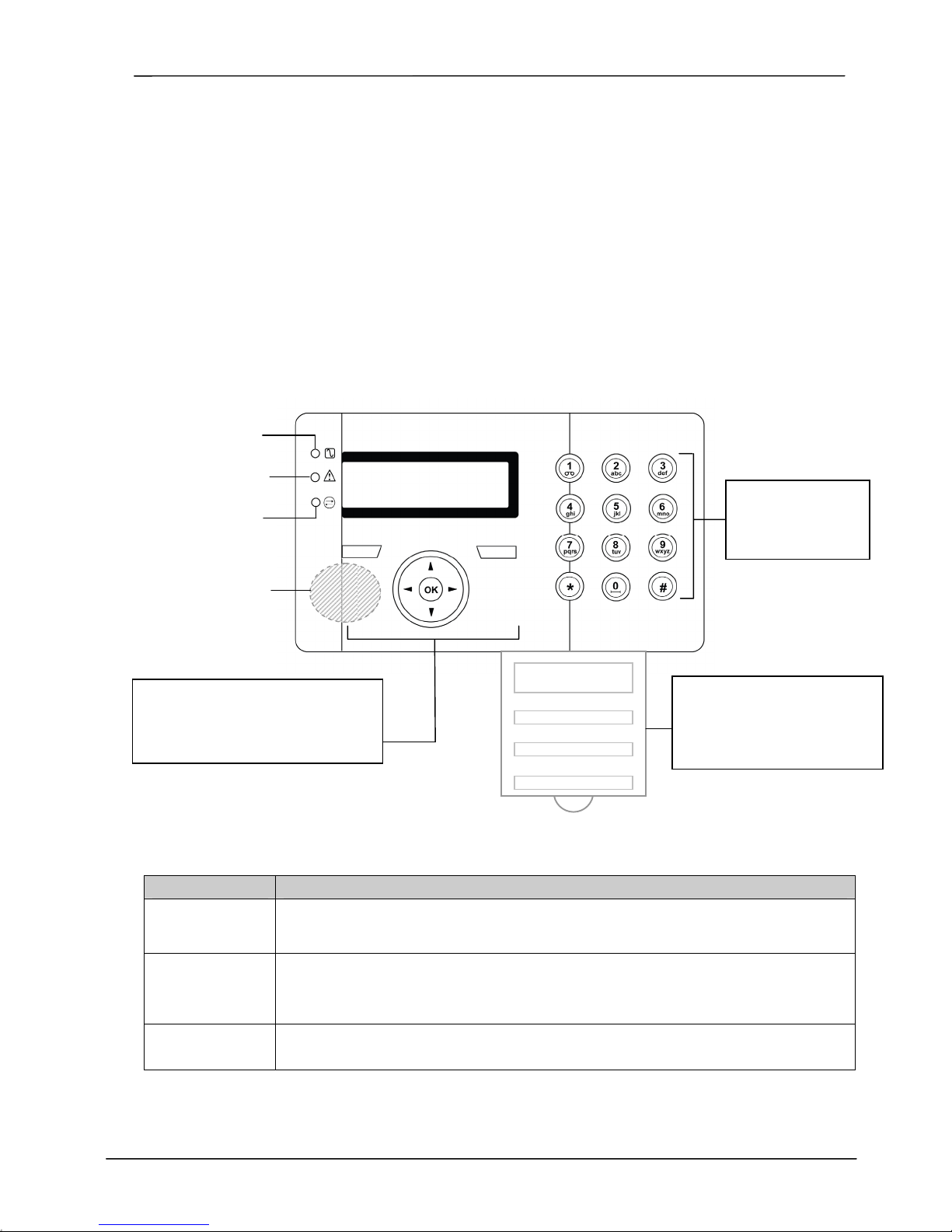
Figure 1 – SigNET Keypad
C Mains LED
System Alert LED
Comms LED
Portable ACE
Receiver Area
Programming Keys
1 x multi-functional navigation key
2 x context sensitive programming
keys (left and right)
Table 1 – LED Status Indicators
LED Description
AC Mains LED
(green)
System Alert
(yellow)
Comms LED
(red)
Indicates presence or failure of the Mains supply
FLASHING: AC Mains fault detected
STEADY: AC Mains OK
Indicates a system alert
FLASHING: System Alert detected; display indicates the location and nature of the alert. If the
system is SET, no indication of system alerts is given.
OFF: No alert detected
Indicates status of the E-BUS communications when in FULL ENGINEER programming
01 Dec 06 17:00
Licence
Details
Installer Contact
Installer Name
Installation Date
Keypad
12 x alphanumeric
keys for numeric
and text data entr
Pull-down Information Tab
The installer contact and licence
details are located on the pull
down information tab at the rear
of the unit
4 E-LAB-1543
SigNET 200/300 User Guide
2.1 Using the Keypad Interface
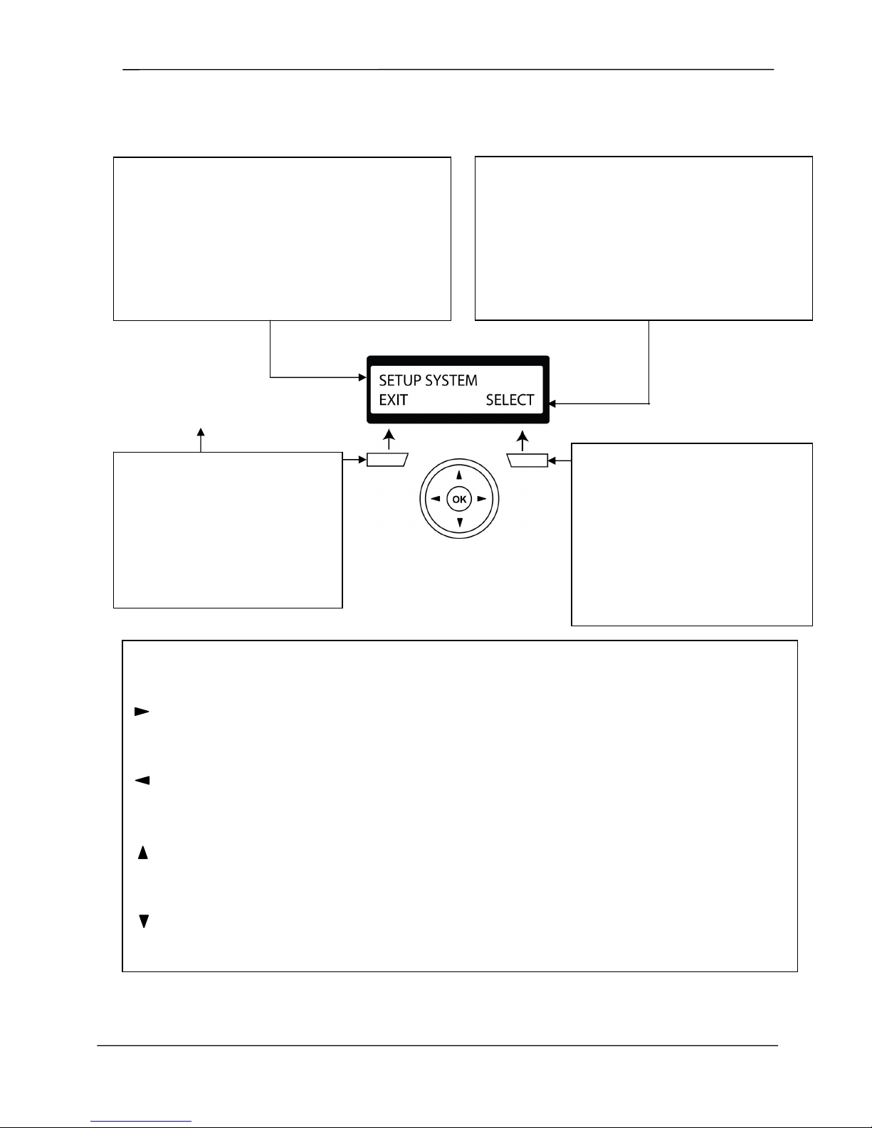
Figure 2 – Keypad Interface
TOP LINE OF DISPLAY
In the IDLE state, this line displays the current date and
time
In Programming Mode, this line displays one of the
following:
→ The programming feature to be selected
→ The current setting of the selected feature
During an alert condition, this line displays the nature of the
current alert
LEFT SOFT KEY
This key is used to select the option
presented on the left side of the
bottom line of the display.
Possible values are:
→ EXIT to exit programming
→ BACK to return to previous menu
MULTI-FUNCTION NAVIGATION KEY
OK The OK button acts as a SELECT key for the menu option displayed on the top line and also as an
ENTER/SAVE key for data displayed on the top line.
In Programming Mode, the right arrow key advances the user through the menus in the same way as pressing
the SELECT option (right soft key). When no more menu options can be selected, this key has no function.
In data entry mode, press this key to move the cursor one position to the right.
In Programming Mode, the left arrow key returns the user to the previous menu level. Pressing this key when
in the top menu level exits the user from programming.
In data entry mode, press this key to move the cursor one position to the left.
In Programming Mode, the up arrow key moves the user to a previous programming option in the same menu
level. Continually press this key to scroll through all programming options available on the current menu level.
In alphanumeric mode, press this key over a lower case character to change the character to upper case.
In Programming Mode, the down arrow key moves the user to the next programming option in the same menu
level. Continually press this key to scroll through all programming options available on the current menu level.
In alphanumeric mode, press this key over an upper case character to change the character to lower case.
BOTTOM LINE OF DISPLAY
In the IDLE state, this line is blank.
In Programming Mode, this line displays the 2 options
available to the user. These options are aligned over the
left and right soft keys for selection as required.
RIGHT SOFT KEY
This key is used to select the option
presented on the right side of the bottom
line of the display.
Possible values are:
→ SELECT to select the option
displayed on the top line
→ ENTER to enter the data displayed on
the top line
→ SAVE to save a setting
E-LAB-1543 5
 Loading...