

European Water Care EWC 10, EWC 12, EWC 18, EWC 23, EWC 30 User Manual
...
1
Softened water is not suitable for drinking.
EWC TIME CLOCK
WATER SOFTENER
Before commencing the installation, please read and understand these instructions. Make
sure you have all the necessary plumbing fittings and tools.
Should you need help or advice, please telephone our helpline on:
01304 827272
Prior to Fitting Your Water Softener
This softener must be Protected from frost and freezing.
Check you have sufficient water mains pressure. This should be:
Minimum operation pressure: 1.5 Bar
Maximum operating pressure: 6 Bar
With an optimum operation pressure of about: 3 Bar
Maximum operating temperature must not be above: 20oC, with a minimum operating temperature of
above freezing:
You can contact your local water authority for your areas mains water pressure. As a rule of thumb, if
you open the kitchen sink cold water tap fully and water splashes everywhere, the pressure could be
too high and if you can easily stop the flow with your thumb it is probably too low. Too low a
pressure, although perfectly possible is unlikely.
If the pressure is too high in your area, you will need to fit a pressure reducing valve. This can be
purchased from your EWC Ltd or your local plumbers merchants. This will prolong the life of the
softener and reduce the risk of flooding due to over pressurisation.
Water hardness test strips with their instructions attached are included with this softener. Follow
attached instructions on the test strips to determine the water hardness of your mains water and record
your results on page 11 of this manual. You will use this data later to set up the water softener.
Next:
Carefully remove the softener from the box, holding by the Cabinet, not the control box.
Important: Never lift by the black control valve/box on top of the cabinet. If you damage
this, it won’t work.
Version 1. 1/12
2
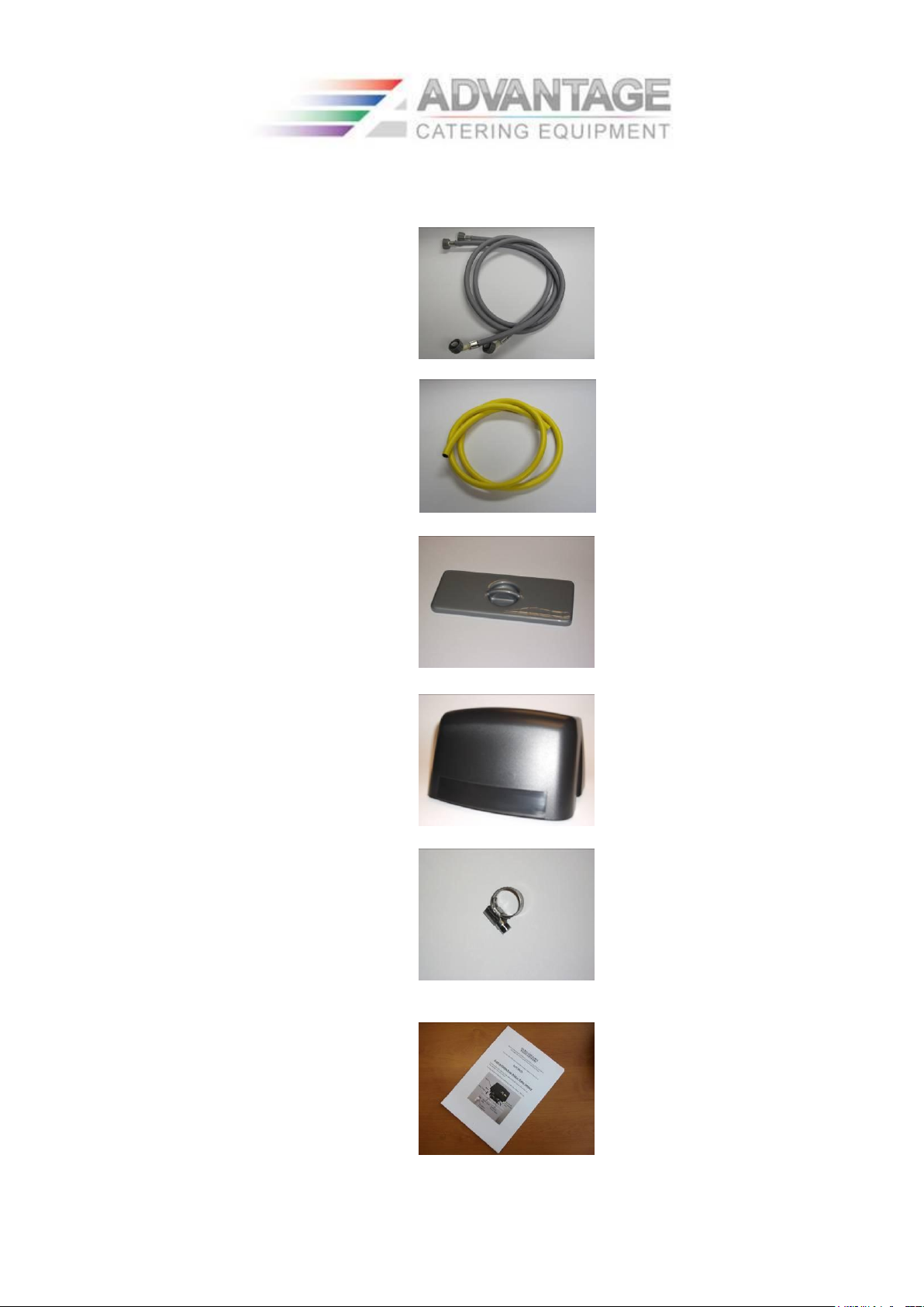
You will also find in the box:
1.) (Optional) 2 x Flexible water supply
hoses. (One inlet and one outlet)
2.) (Optional) 2 metres of drain /
overflow hose
3.) 1 x Salt Lid
4.) 1 x Control Valve Lid
Certain Models only
5.) (Optional )1 x Worm Drive
Clip
7.)1 x Operation Manual
Version 1. 1/12
3
8.) 1 pack of water hardness test strips
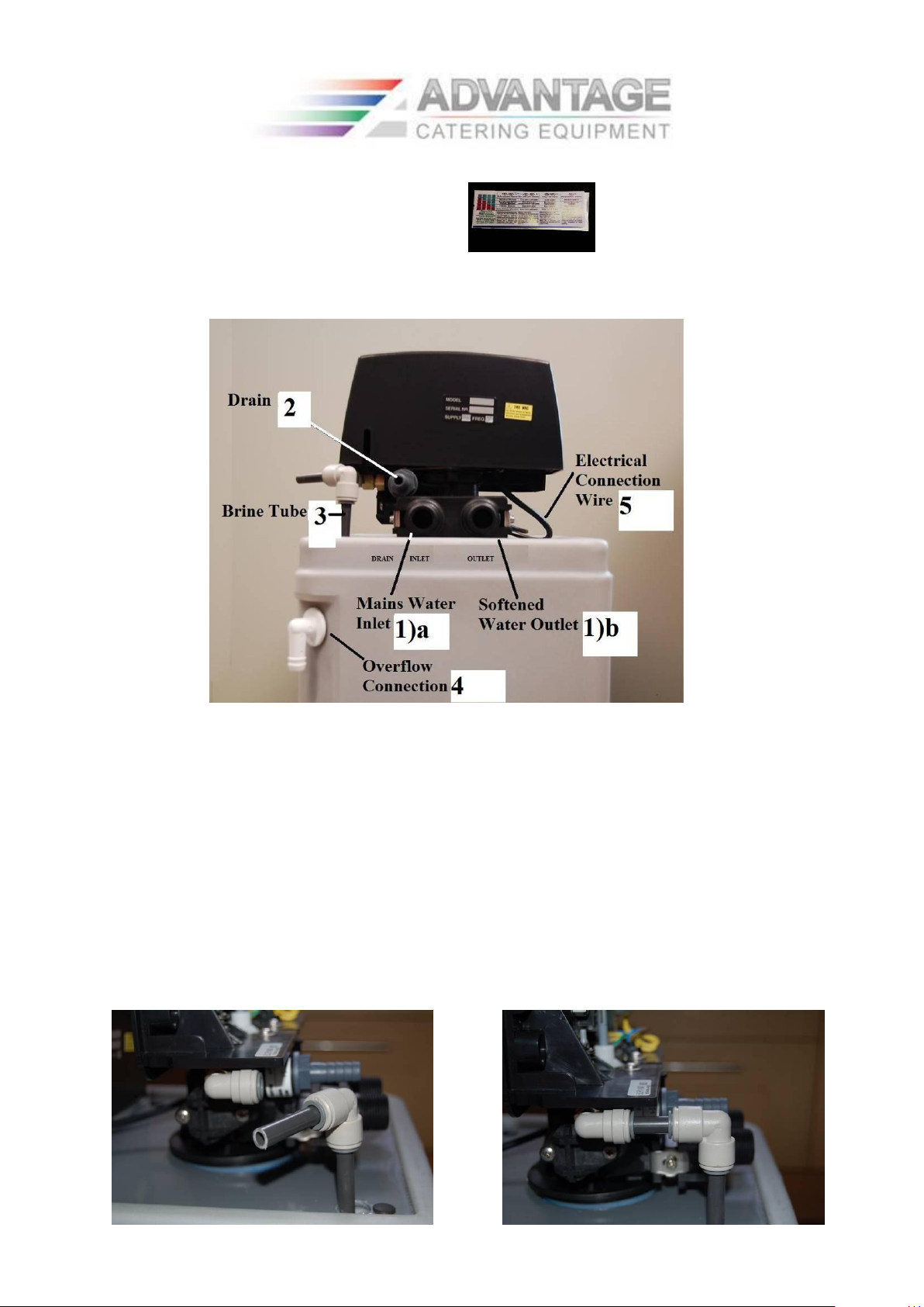
When removed from the box, acquaint yourself with the connections at the rear of the water
softener. These are as follows:
Fig.1
1) 2 x ¾ inch BSP male connections.
a. The left one being the Mains Water Inlet
b. The right one being the Softened Water Outlet
2) A 13 mm hose barb connection on the left hand side. This is the Drain Outlet.
3) A 3/8 inch loose pipe and elbow disappearing into the brine tank cabinet Figs.2 & 3. This
is the Brine Pick Up and is left lose for transportation. This immediately requires connecting
to the push fit elbow on the left hand side of the control valve (see below). Lubricate the end
of the tube with a little water and push firmly into the push fit elbow. Note: If you can easily
pull this out, you didn’t push it home firmly enough.
Fig.2 Fig.3
Version 1. 1/12

4
4) A white, 13mm hose barb elbow, which is located on the tank body. This is the Overflow
Connection and is connected later.
5) The electrical connection cable is located under the control valve, on the right hand side.
INSTALLATION INSTRUCTIONS
Water softeners are very easy to install - there is only 1 electrical and 4 water connections:
1. Mains water inlet
2. Softened water outlet
3. Drain
4. Overflow
5. Electrical connection (which, must be wired into a 240v AC mains power supply).
Before starting, make sure that water will not be needed whilst it is turned off (a full kettle is
a good idea).
(1) DRAIN RISING MAIN
Having decided on a suitable frost-free position for the water softener; turn off the mains
water supply at the stopcock and drain from the lowest point. If you don’t have a drain point
below the place where you intend to fit the valves, turn on the kitchen cold tap until the water
stops running but make sure you have a container of a suitable size, ready to catch any
residual water before you break into the pipe.
Important: The position of the water softener water feed must be after the take-off point for
drinking water and the garden, as softened water is not suitable for drinking or fish ponds and
would prove expensive if used for watering the garden.
(2) FITTTING BYPASS VALVE SET (If applicable)
Cut the rising main in a position which will allow the drinking and garden (‘hard water
supply’) water take-offs, to be situated before to the bypass valve set and softener. Note: You
may also need to run additional pipe-work to alter existing plumbing, if in any doubt, please
contact your local plumber.
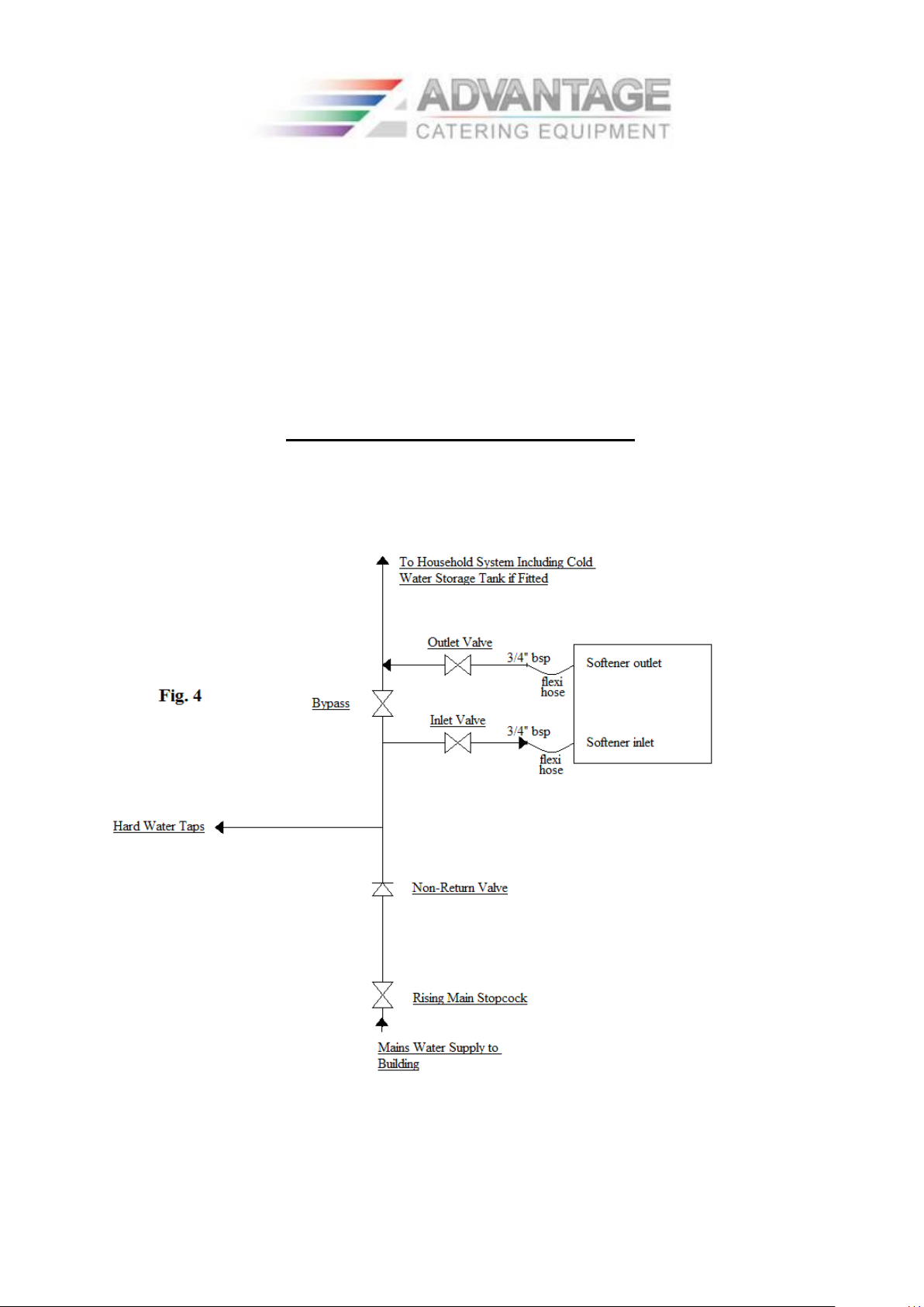
Fit 3 valves as shown in Fig 4 to form a bypass.
This will allow you to maintain water to the house, should you ever wish to remove or
change the softener.
Version 1. 1/12
5
Note: Install proprietary valves with direction of flow arrows as shown, terminating in ¾”
BSP male (this is to accommodate the flexible hoses).
To comply with Water Regulations:
For Domestic installations, you must fit an approved single check non-return valve as shown
in Fig 4.
For Commercial installations, this must be a double check valve.
*Drinking water faucet kits, with or without water filters and purifiers, Triflow taps (giving
hot, cold & drinking water from one monoblock tap) are all available from EWC Ltd. 01279
780250
PIPEWORK INSTALLATION DIAGRAM
Note: Check inlet & outlet are connected in accordance with labels on rear of cabinet
A non-return valve must be fitted in the rising main water pipe prior to the bypass set or in
the hard water inlet pipe. This is to comply with local Water Board Regulations and must be
adhered to.
Version 1. 1/12

6
(3) PLUMB IN THE SOFTENER INLET AND OUTLET HOSES
Using the hoses provided, connect the softener inlet and outlet to the mains water pipe work,
as shown to the previous diagram.
Note: Ensure that the hoses are connected correctly as per the labels on the back of the
softener cabinet
Pressure drop across the system is rarely an issue for households fitted with cold water
storage tanks. Therefore for most households (with cold water storage tanks) and 15mm bypass plumbing, valves etc, the standard hoses provided with the water softener are adequate
to supply all water requirements.
For households with combination boilers i.e. connected directly to the mains water supply
without a cold water storage tank, it would be advisable to disregard the hoses and plumb the
softener directly using all 22mm pipe work valves and fittings etc, especially the non-return
valve. This would give significantly greater flow and less pressure drop across the system
therefore minimizing any low pressure effect on the combination boiler and all the mains
water system through out the house.
(4)
PLUMB IN THE DRAIN
The yellow hose provided is used for both the overflow hose and drain hose and must be
trimmed accordingly. Fit the yellow drain hose provided onto the ½ inch hose barb fitting on
the control valve of the water softener using the jubilee clip, then run the hose to a suitable
drainage point i.e. plastic stand pipe.
Please note: Care should be taken to position the hose so that:
(a) It will not kink or fold
(b) It will not freeze
(c) The length of the drain hose is kept as short as possible
(d) It cannot move and become dislodged.
Note: High water pressure may cause the hose to move during the backwash section of the
water softeners regeneration cycle. For this reason, it is advised to fix the hose in place.
Important: A suitable drain air gap should be provided to adhere to local Water Authority
Bye-Laws. The air gap should be at the point of entry from the drain hose into the drain pipe.
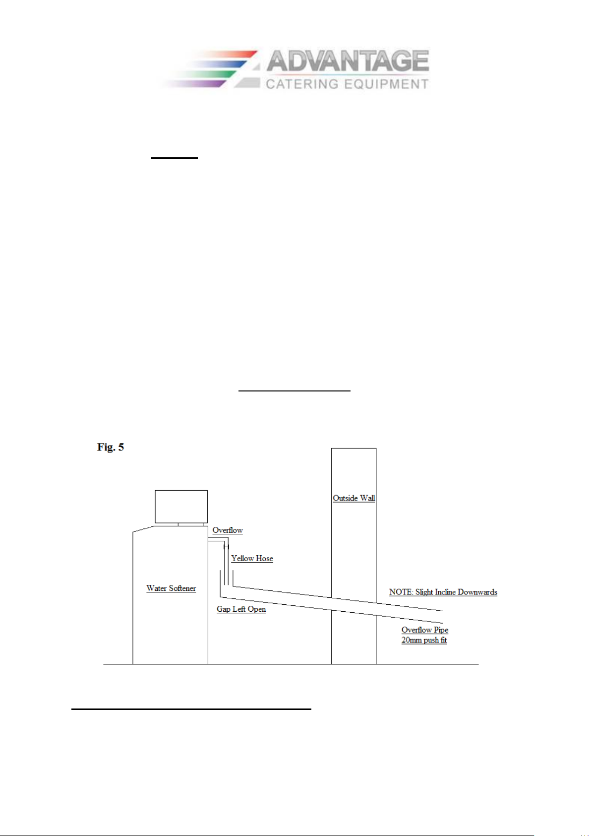
PLUMB IN THE OVERFLOW
It is very important that a good overflow system is provided. Connect a short length of the
yellow hose to the overflow elbow at the rear of the water softener. Run this hose into wider
waste piping of at least ¾ inch (22mm) plastic pipe leading to the outside.
Version 1. 1/12
7
Important: Make sure that no part of the hose, or pipe, run uphill, is kinked, or runs higher
than the overflow outlet. The overflow must always run down hill.
Do not seal the join between the wider piping and the overflow to prevent an air lock forming
(see Fig. 5 ) and DO NOT join the overflow hose to the drain hose - This WILL cause a
flood during the water softeners regeneration cycle.
OVERFLOW SETUP
(5) CONNECT THE ELECTRICITY SUPPLY
The water softener must be wired into a permanent electrical supply i.e. a fused spur
connection.
Version 1. 1/12

8
Maximum fuse 3 amp
Connection for wiring is as follows
Brown - Live
Blue - Neutral
Yellow/Green - Earth
WARNING: This appliance must be earthed. If in doubt consult a qualified electrician.
LOFT OR UPPER FLOOR INSTALLATIONS
Extreme care should be taken with such installations, as the potential for damage, should
there be a leak, could be extremely high.
The water softener must be installed inside a plastic water tank, this tank should then be
provided with a 1 ¼” overflow about half way up the side. This overflow must then be run
outside the building. The water softener overflow may then be ignored. The drain however
must still be installed and great care taken with all joints and protection against freezing.
We strongly advise you contact EWC Service for advice on such installations.
COMMISSIONING THE WATER SOFTENER
CHECK INSTALLATION
Is the:
Inlet to inlet pipe.
Outlet to outlet pipe
Drain and overflow as per instructions
Important: Overflow water will not flow uphill! Don’t forget to check that the drain is not
kinked or in a position where it is possible to kink, freeze or jump out of the drainage pipe
due to water pressure. Get this wrong and it overflows, you will have a flood.
All OK?
Ensure inlet, outlet and bypass valves are closed.
Using the manual regeneration knob, turn the softener control clockwise into the ‘In
Service’ position.
Turn on the mains water supply.
SLOWLY Open inlet valve, you may hear a hissing noise as the water rushes through the
valve.
Once the hissing noise has stopped, open the outlet valve and run some water. Don’t
worry, this may be a brown colour at first, it is a stain washing out of the softener resin
and will do no harm. This will clear in approximately 2-3 minutes
Version 1. 1/12
 Loading...