

European Home Vista 38 ST Installation, Operation And Maintenance Manual
Vista 38 ST
Direct Vent
See-through
Gas Fireplace
Installation,
Operation and
Maintenance
Warning:
Improper installation, adjustment, alteration, service or maintenance can cause injury or
property damage. Refer to this manual. For assistance or additional information consult a
qualied installer, service agency or the gas supplier.
Safety Notice:
Glass doors on gas replaces are extremely hot while the replace is on and remain hot even after the
replace has been turned o. Safety screens are available and can reduce the risks of severe burns.
Please keep children away from the replace at all times.
For Your Safety:
Do not store or use gasoline or other ammable vapors and liquids in the vicinity of this or
any other appliance.
®
C US
Manual
Warning:
What to do if you smell gas
• Do not try to light any appliance.
• Do not touch any electrical switch; do
not use any phone in your building.
• Immediately call your gas supplier from
a neighbor's phone. Follow the gas
supplier's instructions.
• If you cannot reach your gas supplier,
call the re department.
• Installer: Leave this manual with
the appliance.
• Consumer: Keep this manual for
future reference.
Vista 38 ST See-thru Gas Fireplace
Warning:
Read this manual before installing, operating or troubleshooting this appliance. Please
retain this owner's manual for future reference.
Thank You
Thank you for selecting a European Home Gas Fireplace, an elegant and
well-designed gas replace built with you in mind. The gas replace you have
selected is designed to provide the utmost in safety and reliability.
As the owner of this new replace, you'll want to read and carefully follow
all the instructions contained in this installation, operation and maintenance
manual. Pay special attention to all cautions, warnings, and important notes.
This owner's manual should be retained for future reference. We suggest that
you keep it with all your other important documents and product manuals.
The information contained in this owner's manual, unless noted otherwise,
applies to all models and gas control systems.
Welcome to the European Home family of gas replace products. Your new
European Home gas replace will give you years of durable, reliable use.
Safety Alert Key:
• DANGER!
Indicates a hazardous situation which, if not avoided will result in death or serious injury.
• WARNING! Indicates a hazardous situation which, if not avoided could result in death or serious injury.
• CAUTION! Indicates a hazardous situation which, if not avoided, could result in minor or moderate injury.
• NOTICE: Used to address practices not related to personal injury.
• Important: Used to address practices not related to personal injury.
Table Of Contents
Introduction ................................................................................................ 3
Installation
Installing and Framing the Fireplace ..............................................4
Installing the Gas Line ....................................................................5
Vent Installation .............................................................................5
Installation Requirements.........................................................5
Installing the Remote Switch ....................................................5
Vent Terminations ..................................................................... 6
Installing the Nailing Flange .....................................................7
Top Vent Installation ................................................................ 8 - 10
Rear/Side Vent Installation .................................................... 11 - 13
Power Vent Terminations ............................................... 13
Finishing Around the Fireplace ..................................................... 14
Fireplace Facing ............................................................. 14
Mantels and Surrounds .................................................. 14
Wiring ...................................................................................... 15
Removing and Installing the Door ................................................ 16
Installing Fire Media .....................................................................17
Operation ...........................................................................................18 - 20
Maintenance ...................................................................................... 20 - 22
Spare Parts ...................................................................................21
Troubleshooting ........................................................................... 22
Warranty ................................................................................................... 23
Appendix
A. Termination Locations ..............................................................24
B. State of Massachusetts / Amendment ..................................... 25
Page 2
rev.110331
Introduction
Vista 38 ST See-thru Gas Fireplace
About this Fireplace
The Vista 38 ST is a gas replace with a linear burner, available in black painted or
brushed stainless steel.
The Vista 38 ST is rated for 34,000 (maximum) BTU/Hr. (9.38) kilowatts input in natural gas
(NG), and 33,000 (maximum) BTU/Hr. (9.28) kilowatts input in liquid propane (LP).
• Vista 38 ST; uses a millivolt pilot ignition system.
• Vista 38 ST E; uses an electronic ignition system.
This manual covers installation, operation and maintenance. Lighting, operation
and care of this replace can be easily performed by the homeowner. However, all
installation and service work should be performed by a qualied or licensed installer,
plumber, or gas tter who is qualied or licensed by the state, province, region, or
governing body in which the appliance is being installed.
This manual covers all models and unless otherwise specied, the designation Vista 38
ST refers to all variations of the model above. Sections which are specic to a particular
variation are marked with a symbol, plus the appropriate model number.
Warranty and Installation Information:
The European Home warranty will be voided by, and European Home disclaims any
responsibility for the following actions:
• Modication of the replace and/or components including direct vent assembly or
glass doors.
• Use of any component part not manufactured or approved by European Home in
combination with this European Home replace system.
• Installation other than as instructed in this manual.
Consult your local Gas Inspection Branch on installation requirements for factorybuilt gas replaces. Installation and repairs should be done by a qualied contractor.
Installations in Canada must conform to the current CAN/CGA B-149.1 and .2 Gas
Installation Code and local regulations. If the optional air-circulating fan kit is installed,
it must be electrically grounded in accordance with CSA C22.1 Canadian Electrical
Code Part 1 and/or Local Codes.
Installations in the USA must conform to local codes, or in the absence of local codes
to the National Fuel Gas Code, ANSI Z223.1-1988. If the optional air-circulating fan
is installed, it must be grounded in accordance with local codes or, in the absence of
local codes, with the National Electrical Code, ANSI/NFPA 70-1987. See Appendix
for installation within the State of Massachusetts. This replace must comply with
NFPA-54 Chapter 10.
What is Combustible?
Materials that can catch re and burn are considered combustible. Any material that
is made of, or faced with, wood, wood pulp, paper, plastic or any other material that
can catch re and burn is considered combustible. Even though these materials may
have been 'ame-proofed', made 're-resistant' or are 're-rated' they are considered
combustible.
The combustibility of a material can be tested per "ASTM E136 Standard Test Method
for Behavior of Materials in a Vertical Tube Furnace at 750 Degrees C". Note that 'reresistant' does NOT mean non-combustible.
Note: If a certain material has a core considered to be non-combustible (in accordance
with ASTM E136) but is faced with a combustible material then the material is
considered to be combustible.
When in doubt, ask for an ASTM E136 compliance statement.
What is Non-combustible?
A given material is said to be non-combustible when it cannot catch re and burn.
For example, materials made entirely, or in combinations, of, stone, brick, concrete,
tile, steel, plaster or glass are considered non-combustible.
For the purposes of the installations described in this Manual, those materials that
have passed the ASTM E136 tests are considered to be non-combustible.
As of this writing, the materials listed below are reported by their manufacturers to
be non-combustible (in accordance with ASTM E136):
• James Hardie Building Products, Inc.:
HardieBacker™ ¼” Cement Board
• U.S. Architectural Products, Inc.:
Versaroc® Cement Bonded Particle Board
Cem-Clad® Cement Panel
WARNING!
When this appliance is installed directly on carpeting, tile or any combustible
material other than wood ooring, it must be installed on a metal or wood
panel extending the full width and depth of the appliance.
rev.110331
CAUTION!
Due to its high operating temperatures, the appliance should be
located out of trac and away from furniture and draperies.
• Children and adults should be alerted to the hazards of the
high surface temperature, which could cause burns or clothing
ignition.
• Young children should be carefully supervised when they are in
the same room as the appliance.
• Clothing or other ammable materials should not be placed on
or near the appliance.
Page 3
Vista 38 ST See-thru Gas Fireplace
Installation
Installing the Fireplace Shell
The replace may be installed in any location that maintains proper clearances to air
conditioning ducts, electrical wiring and plumbing. Safety, as well as eciency of
operation, must be considered when selecting the replace location. Try to select a
location that does not interfere with room trac, has adequate ventilation, and oers
an accessible pathway for the venting installation. Refer to page 4 - Vent Installation
for more information.
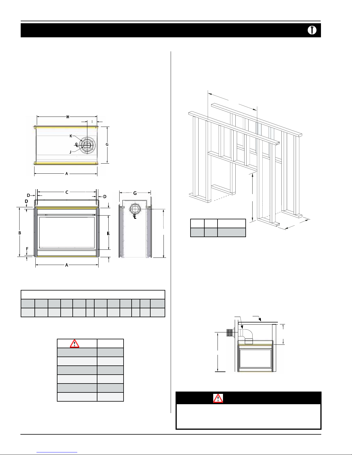
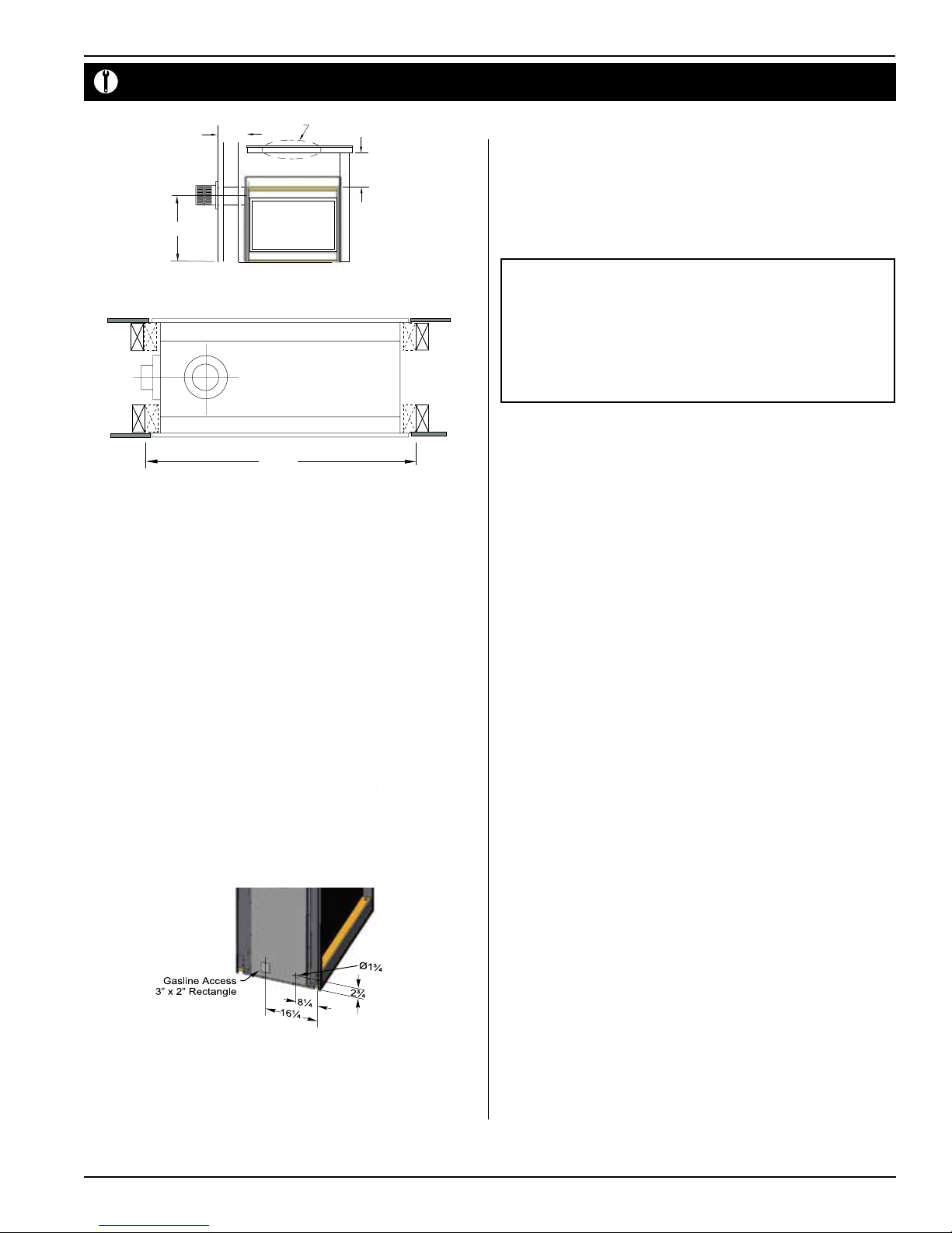
The replace dimensions for Vista 38 ST models are shown below:
Top View
(Minimum 1" clearance must still be maintained around the vent pipes, except on
horizontal venting sections where the top of the pipe must have a clearance of 2")
For protection against freezing temperatures, it is recommended that outer walls of
the chase be insulated with a vapor barrier. This will reduce the possibility of a cold
air convection current on the replace.
Framing
N
M
6¼
5¼
Side View
Front View
Figure 1. Fireplace dimensions.
Vista 38 ST Fireplace Dimensions (inches)
A B C D E F G H I J K L
37¾ 36½ 35¼ 1¼ 25 1 24 36¼ 7⁄ 5 8 33½
Clearances
The clearances to combustible materials are:
Vista 38 ST
Top (top vented)* 19"
Top (rear vented) 10"
Fronts 2"
Sides 1"
* Clearance from the top of the replace to a combustible
ceiling within the replace enclosure.
** Refer to page 14.
Floor 0"
Mantle** 4"
M N O
L
Figure 2. Framing dimensions.
42½ 40¾ 23¾or 24¾*
* When facing with the Overlay
Method the depth is increased by
1". See Planning Guide for more
information.
1.) Frame the replace cavity (thru-wall design) according to Figure 2.
2.) Frame your installation, Figure 2a if the design incorporates a shelf over the
replace.
3.) Once complete, slide the replace into the completed cavity.
4.) Next, tack four jack studs (vertical, "broken line") in place, Figure 2c.
5.) Secure the replace in position by nailing/screwing the replace ange into
these jack studs.
PEL Short
90 elbow
RHS101
46½"
minimum
shelf
19"
minimum
Figure 2a. Framing dimensions. (top vent)
WARNING!
When this appliance is installed directly on carpeting, tile or any combustible
material other than wood ooring, it must be installed on a metal or wood
panel extending the full width and depth of the appliance.
O
Page 4
rev.110331
Installation
Figure 3. Gas line access.
Vista 38 ST See-thru Gas Fireplace
12"
max.
RHS101
33½"
shelf
10"
minimum
Figure 2b. Framing dimensions. (rear vent)
41”
Figure 2c. Back frame dimensions.
Installing The Gas Line
The gas line must be installed before nishing the Vista 38 ST replace. Natural Gas
requires a minimum inlet gas supply pressure of 5.5" w.c. and a manifold pressure of
3.5" w.c. Propane Gas requires a minimum inlet gas supply pressure of 11" w.c. and
a manifold pressure of 10" w.c. Provision must also be made for a ⁄" N.P.T. plugged
tapping and be accessible for test gauge connection immediately upstream of the
gas supply controls to the appliance. The replace gas connection and the main
operating gas valve is located behind the removable trim at the bottom of the unit
and need only be attached to the gas line with an approved tting, as required by
the applicable installation codes.
• Only use gas shut-o valves approved for use by the state, province, region, or
governing body, in which the appliance is being installed, or as required by the
applicable installation codes.
• Flexible gas connectors must not exceed 3 feet in length, unless it is allowable within
applicable installation codes.
The appliance and its individual shut-o valve must be disconnected from the gas
supply piping system during any pressure testing of that system at test pressures in
excess of ½ psig (3.5 kPa).
The appliance must be isolated from the gas supply piping system by closing its
individual manual shut-o valve during any pressure testing of the gas supply piping
system at test pressures equal to or less than ½ psig (3.5 kPa).
Note: After the gas line is connected, each appliance connection, valve and
valve train must be checked while under normal operating pressure
with either a liquid solution, or leak detection device, to locate any
source of leak. Tighten any areas where bubbling appears or leak is
detected until bubbling stops completely or leak is no longer detected.
DO NOT use a ame of any kind to test for leaks.
Installing The Remote Switch
The Vista 38 ST gas valve, located behind the lower trim, is connected to a length
of thermostat wire and is switched by a remote controlled receiver. Strip the wire
insulation back ½" and connect the white and black wires to the receiver.
Note: The switch location must not exceed 30' from the replace.
Vent Installation
This section covers the installation of direct venting and terminations.
Installation Requirements
•
Vista 38 ST Series replaces are certied for use with European Home Standard Series
(5"/8") venting components.
•
Minimum clearance to combustible construction around the vent pipe is 1" on all sides,
except on horizontal venting where the top of the pipe must have a clearance of at least
2".
•
Use only certied European Home vent components. Use of other parts will void the
European Home warranty and may impede the operation of the replace.
•
All joints must be secured with a minimum of two screws per joint.
•
Vent terminations must not be recessed in walls or siding.
•
Horizontal runs must be suppor ted by a minimum of two supports per horizontal run. A
minimum of one screw on each side of support is also required.
•
Flex vent sections may be stretched up to 50% of their total length (e.g. a 24" section may
be stretched to 36".)
• Venting components can be used in any combination of solid/rigid.
rev.110331
• Solid vent sections may be cut less than half way from the tapered end.
•
Venting components can be used in any combination of solid/rigid pipe or ex pipe and
in any orientation, i.e. male connectors can face in any direction.
Page 5
Vista 38 ST See-thru Gas Fireplace
12
12
11
11
1212
12
Installation
CAUTION!
Due to its high operating temperatures, the appliance should be
located out of trac and away from furniture and draperies.
Children and adults should be alerted to the hazards of the
high surface temperature, which could cause burns or clothing
ignition.
Young children should be carefully supervised when they are in
the same room as the appliance.
Clothing or other ammable materials should not be placed on
or near the appliance.
CAUTION:
Do not obstruct, or attempt to conceal, the vent termination. These actions
will aect the operation of the replace, and may be hazardous.
In heavy snow areas, take extra care to prevent snow buildup from obstructing
the vent termination.
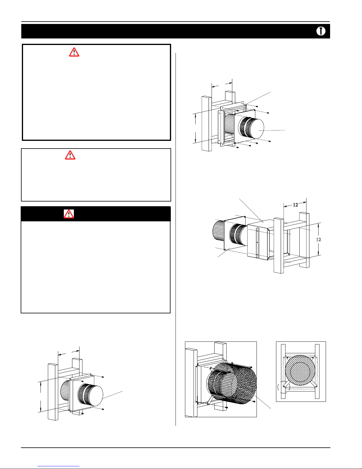
Caution:
1. Frame the termination opening to 11" x 11".
2. Fasten the termination to the studs using a minimum of 4 screws.
Installing Terminations with MSR Frames
MSR
PTO-4F (5"/8")
Figure 4b. Installing a PTO termination with the MSR frame.
1. Frame the termination opening to 12" x 12".
2. Fasten the termination to the studs using a minimum of 4 screws.
Installing Terminations with MOSR Frames
MOSR
Vent terminations can be very hot. If the termination is less than 7 feet above a
public walkway, it should be tted with a certied European Home Heat Guard.
(Part no. PTKOG).
Do not obstruct, or attempt to conceal the vent termination. These actions
will aect the operation of the replace, and may be hazardous.
In heavy snow areas, take extra care to prevent snow buildup from obstructing
the vent termination.
Use European Home Vinyl Heat Shield (Part no. VSS) when using on applica-
tions with vinyl siding to guard against possible damage.
Installing Terminations with Built-In Frames
PTO-4 (5"/8")
PTO-4 (5"/8")
Figure 4c. Installing a PTO termination with the MOSR frame.
1. Frame the termination opening to 12" x 12".
2. Fasten the MOSR frame to the interior side of the studs using a minimum of 4
screws.
3. Insert the termination into the MOSR frame as shown here, and attach by
screwing through the four pilot holes in the termination.
Installing Heat Guards over Terminations
PTKOG (5"/8")
Figure 4a. Installing a PTO termination.
Page 6
Figure 4d. Installing a PTO termination heat guard.
rev.110331
Installation
Vista 38 ST See-thru Gas Fireplace
1. Ensure that the two long mounting brackets are facing the bottom of the
termination. (See inset). This will provide more heat protection at the top of
the termination, where temperatures are highest.
2. Attach to the faceplate of the termination using four sheet metal screws.
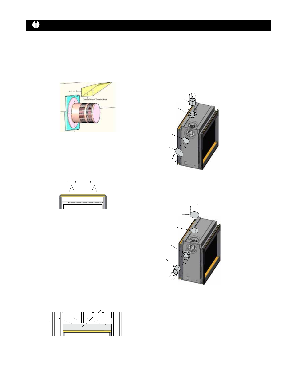
Installing Heat Shield for Vinyl Siding
Figure 5. Installing the VSS Vinyl Shield heat guard.
Installing The Standos
To avoid elevated mantel temperatures, all Vista 38 ST Series gas replaces are
required to have the supplied standos installed.
The replace is supplied with two standos. Bend and install these standos
on top of the replace ensuring that the height of the stando maintains a 6"
clearance.
Converting the Vista 38 ST from
Top Vent to Side Vent
Top Vent
Use the following instructions to convert a Vista 38 ST for top vent or side vent use.
Top Vent
1. Install the 5" inner ue collar on
5” Inner
Flue Collar
8” Outer
Flue Collar
5” Inner Flue
Cover Plate
8” Outer Flue
Cover Plate
the top ue outlet and secure
the cap in place with four (4)
screws, as shown in Figure 8.
2. Install the 8" outer ue collar on
the top ue outlet, and secure it
with ve (5) screws, as shown
in Figure 8.
3. Install the ue gasket material
and ue cover plate on the side
vent outlet . Fasten the cover
plate(s) with four (4) and ve
(5) screws, as illustrated.
Figure 6. Installing the standos.
Installing the Nailing Flange Extension
Once the replace is placed into the framed opening, the supplied nailing extension must placed along the top edge of the replace, and nailed in place to the
framing, as illustrated below. The supplied nailing extension must be placed
along the top edge of the replace and securely fastened in place to the lintel and
combustible wood framing.
Note: The nailing ange extension can be substituted with a piece of NON-
COMBUSTIBLE material of the same size and thermal characteristics, i.e.; cement
board or equivalent.
Nailing Flange Extension
Figure 8. Installing the top vent/side ue covers.
8” Outer Flue
Cover Plate
5” Inner Flue
Cover Plate
8” Outer
Flue Collar
5” Inner
Flue Collar
Figure 8a. Installing the side vent/top ue covers.
Side Vent
1. Install the 5" inner ue collar
on the side ue outlet and
secure the cap in place with
four (4) screws, as shown in
Figure 8a.
2. Install the 8" outer ue collar
on the side ue outlet, and
secure it with ve (5) screws,
as shown in Figure 8a.
3. Install the ue gasket material
and ue cover plate on the top
vent outlet. Fasten the plate
with four (4) screws, and ve
(5) crews as illustrated.
4. Install the 4" or 5" inner ue
collar and the 7" or 8" outer
flue collar in place on the
side vent outlet using ve (5)
screws, as illustrated below.
Figure 7. Installing the nailing ange extension.
rev.110331
Page 7
Vista 38 ST See-thru Gas Fireplace
Installation
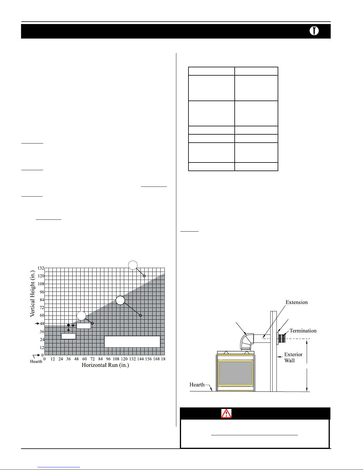
Top Vent Venting Requirements
Before you install any venting, you must determine whether the venting run will
be acceptable. Unacceptable venting can aect the replace's combustion.
• for installations with horizontal venting runs of 0-16 feet, use the vent graph,
as described below
• the maximum horizontal vent run is 16 feet.
Measure the vertical height from the replace hearth to the center of the termination and the horizontal run from the from the replace ue collar to the wall ange
of the termination. Plot on the venting graph, Figure 9 with an 'X'.
If the 'X' falls on or above the top boundary of the shaded area, the installation is
acceptable.
Example A: (Acceptable Installation)
If the vertical dimension from the hearth is 112", and the horizontal run to
the wall ange of the vent termination is 150", the installation is acceptable.
Example B: (Unacceptable Installation)
If the vertical dimension from the hearth is 48" and the horizontal run to the
wall ange of the vent termination is 72", the installation is N OT ALLOWED.
Example C: (Unacceptable Installation)
If the vertical dimension from the oor of the replace is 60" and the horizontal run to the wall ange of the vent termination is 144", the installation
is NOT ALLOWED.
Installation Of Top Venting
The following components are available for through-the-roof venting:
A - Termination PVTK-1
B - Flex Sections PFL-1 (12" section)
PFL-2 (24" section)
PFL-3 (36" section)
PFL-4 (48" section)
C - Rigid Sections PEXT-1 (12" m/f section)
PEXT-2 (24" m/f section)
PEXT-3 (36" m/f section)
PEXT-4 (48" m/f section)
D - Support Ring and Plate PSPXT-8
E - Firestop PS-8
F - Roof Flashing FRF-8 (at roof)
PRF-7 (1/12 - 7/12 pt.)
PRF-12 (7/12 - 12/12 pt.)
G - Adaptor/Vent Reducer PVA5487 (5"/8" to 4"/7")
48” LP
36” NG
Figure 9. Top Vent Venting Graph.
B
46” NG
A
C
Powered venting to be used within
the shaded area of graph.
Example:
A 10' section and an elbow used in conjunction with 3 ft. ex section (PFL-3) will,
when extended in a ve foot chase, allow for a maximum horizontal run of twelve
and one-half feet from the center of the replace to outside wall and a minimum
of 7'6" when retracted in opposite direction. See Figure 11 and 12.
"D" ex sections and "E" solid sections may be used in conjunction with one
another in various possible horizontal vent installations. NOTE: Flex section must
not exceed maximum horizontal length of 3 feet. See Figure 13.
Insulated
Sleeve
CRS101
RHS 101
50”
Figure 10. Short horizontal installation.
Page 8
WARNING:
Ensure RHS vent heat shields have a minimum 1" clearance on bottom and sides
from framing. Top must have minimum 2" clearance as shown.
rev.110331
 Loading...