

European Home VISION GAS FIREPLACE Installation, Operation And Owner's Manual
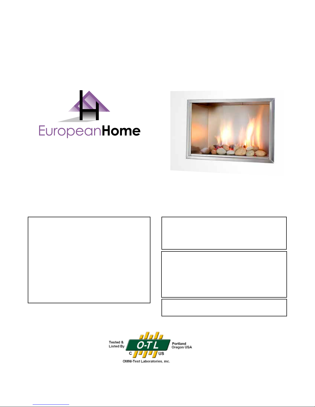
VISION GAS FIREPLACE
Installation, Operation and Owner’s Manual
WHAT TO DO IF YOU SMELL GAS
• Do not try to light any appliance.
• Do not touch any electrical switch; do
not use any phone in your building.
• Immediately call your gas supplier
from a neighbor’s phone. Follow the
gas supplier’s instructions.
• If you cannot reach your gas supplier,
call the re department.
Report #284-F-01-5
WARNING: If the information in these
instructions is not followed exactly, a re
or explosion may result causing property
damage, personal injury or loss of life.
Do not store or use gasoline or other
flammable vapors and liquids in the vicinity
of this or any other appliance. Installation
and service must be performed by a qualied
installer, service agency or the gas supplier.
Ce manual est disponsible en Français sur demande.
July 2014
1

TABLE OF CONTENTS
Important Safety Information 4
Before You Begin 7
Specications and Dimensions 8
Electrical Requirements 11
Installation Clearances 12
Combustion Air Supply 15
Framing 18
Installing the Fireplace 19
Gas Supply 19
Venting 20
Facing 21
Installing the Burner Module 23
Panel Installation 27
Stone Conguration 28
Surrounds 30
Lighting Instructions 31
Maintenance 34
VBM Troubleshooting 36
24VBM Troubleshooting 38
Parts List 39
Warranty 40
Third-Party Connections Appendix A
Power Venting the Vision Gas Fireplace Appendix B
2

IMPORTANT SAFETY INFORMATION
1. The installation must conform with local codes or, in the absence of local codes, with the National Fuel Gas
Code, ANSI Z223.1 or the Canadian Installation Code, CAN/CGA B149.1.
2. The appliance and its appliance main gas valve must be disconnected from the gas supply piping system
during any pressure testing of that system at test pressures in excess of ½ psi (3.5 kPa).
3. The appliance must be isolated from the gas supply piping system by closing its equipment shuto valve
during any pressure testing of the gas supply system at test pressures equal to or less than ½ psi (3.5 kPa).
4. The installation must provide for adequate ventilation air to the appliance.
5. This gas appliance must not be connected to a chimney ue serving a separate solid-fuel burning appli-
ance.
6. The appliance, when installed, must be electrically grounded in accordance with local codes, or, in the
absence of local codes, with the National Electrical Code ANSI/NFPA 70, or the Canadian Electrical Code, CSA
C22. 1.
7. When the appliance is installed directly on carpeting or tile or other combustible material other than wood
ooring, the appliance shall be installed on a metal or wood panel extending the full width and depth of
the appliance. The bottom of the replace complies with this requirement.
8. The appliance area must be kept clear and free from combustible materials, gasoline and other ammable
vapors and liquids.
9. The ow of combustion and ventilation air must not be obstructed.
10. Do not use this appliance if any part has been under water. Immediately call a qualied service technician
to inspect the appliance and to replace any part of the control system and any gas control which has been
under water.
11. Due to high temperatures, the appliance should be located out of trac and away from furniture and drap-
eries.
12. Children and adults should be alerted to the hazards of high surface temperatures and should stay away to
avoid burns or clothing ignition.
13. Young children should be carefully supervised when they are in the same room as the appliance.
14. Clothing or other ammable material should not be placed on or near the appliance.
15. Any screen or guard removed for servicing an appliance must be replaced prior to operating the appliance.
16. This appliance is not for use with glass doors.
17. Installation and repair should be done by a qualied service person. The appliance should be inspected
before use and at least annually by a professional service person. More frequent cleaning may be required
due to excessive lint from carpeting, bedding material, etc. It is imperative that the control compartments,
burners and circulating air passageways of the appliance be kept clean.
18. This appliance is equipped for use with natural gas or propane and is not convertible to the other fuel.
19. This appliance has been certied by OMNI-Test Laboratories, Inc. to ANSI Z21.50b-2005 • CSA 2.33a-2003
Vented Gas Fireplaces and CAN1-2.17-M91, Gas-Fired Appliances for Use At High Altitudes.
20. This appliance is approved for installation in the Commonwealth of Massachusetts. The Board of State
Examiners of Plumbers and Gas Fitters has issued approval number G3-0113-334 for this appliance.
21. This appliance is approved for installation in New York City. The Department of Buildings has issued MEA
number 26-06-E for this appliance.
3
AVERTISSEMENT: Assurez-vous de bien suivre les instructions données dans cette
notice pour réduire au minimum le risque d’incindie ou d’explosion ou pour éviter tout
dommage matériel, toute blessure ou la mort.
Ne pas entreposer ni utilizer d’essence ni d’autres vapeurs ou liquides inammables dans le voisinage de cet appareil ou de tout autre appareil.
QUE FAIRE SI VOUS SENTEZ UNE ODEUR DE GAZ:
• Ne pas tenter d’allumer d’appareil.
• Ne touchez à aucan interrupteur. Ne pas vous servir des téléphones se trouvant dans le bâtiment où vous trouvez.
• Appelez immédiatement votre fournisseur de gaz depuis un voisin. Suivezles instructions du
fournisseur.
• Si vous ne pouvez rejoindre le fournisseur de gaz, appelez le service des incindie.
L’installation et l’entretien doivent être assurés par un installateur ou un service d’entretien qualié
ou par le fournisseur de gaz.
Attention. Au moment de l’entretien des commandes, étiquetez tous les ls avant de les débrancher.
Des erreurs de câblage peuvent entraîner un functionnement inadéquat et dangereux. S’assurer que
l’appariel fonctionne adéquatement une fois l’entretien terminé.
Cet appareil doit être ustilisé uniquement avec les types de gaz indiqués sur la plaque signalétique.
Cet appareil ne peut être converti a d’autres gaz.
AVERTISSEMENT: Risque de dommages ou de blessures si les pièces ne sont pas installées conformément à ces schémas et ou si des pièces autres que celles spéciquement approuvées avec cet appareil
sont utilsées.
Les dêgagements sont conformes aux codes d’installation locaux et aux exigences du fournisseur de
gaz.
NE PAS UTILISER AVEC DES PORTES EN VERRE.
Le registre doit être en position ouverte lorsque le ou les brûleurs principaux de l’appariel fonctionnent.
Ne pas se servir de cet appareil s’il a été plongé,dans l’eau, même partiellement. Faire inspecter l’appareil par un technicien qualié et remplacer toute partie du système de commande et toute commande
qui ont été plongée dans l’eau.
4

Installations in the Commonwealth of Massachusetts must observe the following:
5.08: Modications to NFPA-54, Chapter 10
Revise 10.8.3 by adding the following additional requirements:
(a) For all side wall horizontally vented gas fueled equipment installed in every dwelling, building
or structure used in whole or in part for residential purposes, including those owned or operated by
the Commonwealth and where the side wall exhaust vent termination is less than seven (7) feet above
nished grade in the area of the venting, including but not limited to decks and porches, the following
requirements shall be satised:
1. INSTALLATION OF CARBON MONOXIDE DETECTORS. At the time of installation of the side wall
horizontal vented gas fueled equipment, the installing plumber or gastter shall observe that a hard wired
carbon monoxide detector with an alarm and battery back-up is installed on the oor level where the gas
equipment is to be installed. In addition, the installing plumber or gastter shall observe that a battery
operated or hard wired carbon monoxide detector with an alarm is installed on each additional level of
the dwelling, building or structure served by the side wall horizontal vented gas fueled equipment. It
shall be the responsibility of the property owner to secure the services of qualied licensed professionals
for the installation of hard wired carbon monoxide detectors
a. In the event that the side wall horizontally vented gas fueled equipment is installed in a
crawl space or an attic, the hard wired carbon monoxide detector with alarm and battery back-up
may be installed on the next adjacent oor level.
b. In the event that the requirements of this subdivision can not be met at the time of
completion of installation, the owner shall have a period of thirty (30) days to comply with the
above requirements; provided, however, that during said thirty (30) day period, a battery operated
carbon monoxide detector with an alarm shall be installed.
2. APPROVED CARBON MONOXIDE DETECTORS. Each carbon monoxide detector as required in
accordance with the above provisions shall comply with NFPA 720 and be ANSI/UL 2034 listed and IAS
certied.
3. SIGNAGE. A metal or plastic identication plate shall be permanently mounted to the exterior of the
building at a minimum height of eight (8) feet above grade directly in line with the exhaust vent terminal
for the horizontally vented gas fueled heating appliance or equipment. The sign shall read, in print size
no less than one-half (½) inch in size, "GAS VENT DIRECTLY BELOW. KEEP CLEAR OF ALL OBSTRUCTIONS".
4. INSPECTION. The state or local gas inspector of the side wall horizontally vented gas fueled
equipment shall not approve the installation unless, upon inspection, the inspector observes carbon
monoxide detectors and signage installed in accordance with the provisions of 248 CMR 5.08(2)(a)1
through 4.
(b) EXEMPTIONS: The following equipment is exempt from 248 CMR 5.08(2)(a)1 through 4:
1. The equipment listed in Chapter 10 entitled "Equipment Not Required To Be Vented" in the most
current edition of NFPA 54 as adopted by the Board; and
5

2. Product Approved side wall horizontally vented gas fueled equipment installed in a room or
structure separate from the dwelling, building or structure used in whole or in part for residential purposes.
(c) MANUFACTURER REQUIREMENTS - GAS EQUIPMENT VENTING SYSTEM PROVIDED. When the
manufacturer of Product Approved side wall horizontally vented gas equipment provides a venting
system design or venting system components with the equipment, the instructions provided by the
manufacturer for installation of the equipment and the venting system shall include:
1. Detailed instructions for the installation of the venting system design or the venting system
components; and
2. A complete parts list for the venting system design or venting system.
(d) MANUFACTURER REQUIREMENTS - GAS EQUIPMENT VENTING SYSTEM NOT PROVIDED. When the
manufacturer of a Product Approved side wall horizontally vented gas fueled equipment does not provide
the parts for venting the ue gases, but identies "special venting systems", the following requirements
shall be satised by the manufacturer:
1. The referenced "special venting system" instructions shall be included with the appliance or
equipment installation instructions; and
2. The "special venting systems" shall be Product Approved by the Board, and the instructions for
that system shall include a parts list and detailed installation instructions.
(e) A copy of all installation instructions for all Product Approved side wall horizontally vented gas
fueled equipment, all venting instructions, all parts lists for venting instructions, and/or all venting design
instructions shall remain with the appliance or equipment at the completion of the installation.
6

BEFORE YOU BEGIN
Thank you for purchasing the Vision Gas Fireplace by European Home.
Please read this manual thoroughly before beginning the installation of your Vision Gas Fireplace. It
has information which is important for safe, trouble-free installation and operation.
You have ordered your Vision Gas Fireplace with one of two available burners; a VBM or a 24VBM.
The VBM burner has an adjustable ame height and the 24VBM burner has a xed ame height.
The listing label on the burner module will identify which of the two burners you have. No matter
which burner you have, the Vision Gas Fireplace cabinet and venting are installed identically. The difference in the installation of the burners is detailed in the INSTALLING the BURNER MODULE section.
NOTE!
Remove the combustion air door required in your particular installation. See the
COMBUSTION AIR SUPPLY section for details.
Reset the Vision Gas Fireplace. See the MAINTENANCE section for details.
You should have the following tools and supplies:
• 8” Type B vent pipe and appropriate draft
hood connector (see VENTING section)
• Saw
• Hammer
• Wire stripper and crimping pliers
• Phillips and straight-blade screwdrivers
• Plumb line and level
• Tape measure and framing square
• Electric drill and assortment of drill bits
• Safety glasses and gloves
• Framing material
• Manometer
• #6 or #8 self-tapping screws, ½” ¾” long
• Leak detection uid (non-corrosive) or gas
detector
• 24V AC-rated switch (24VBM burner ONLY)
7
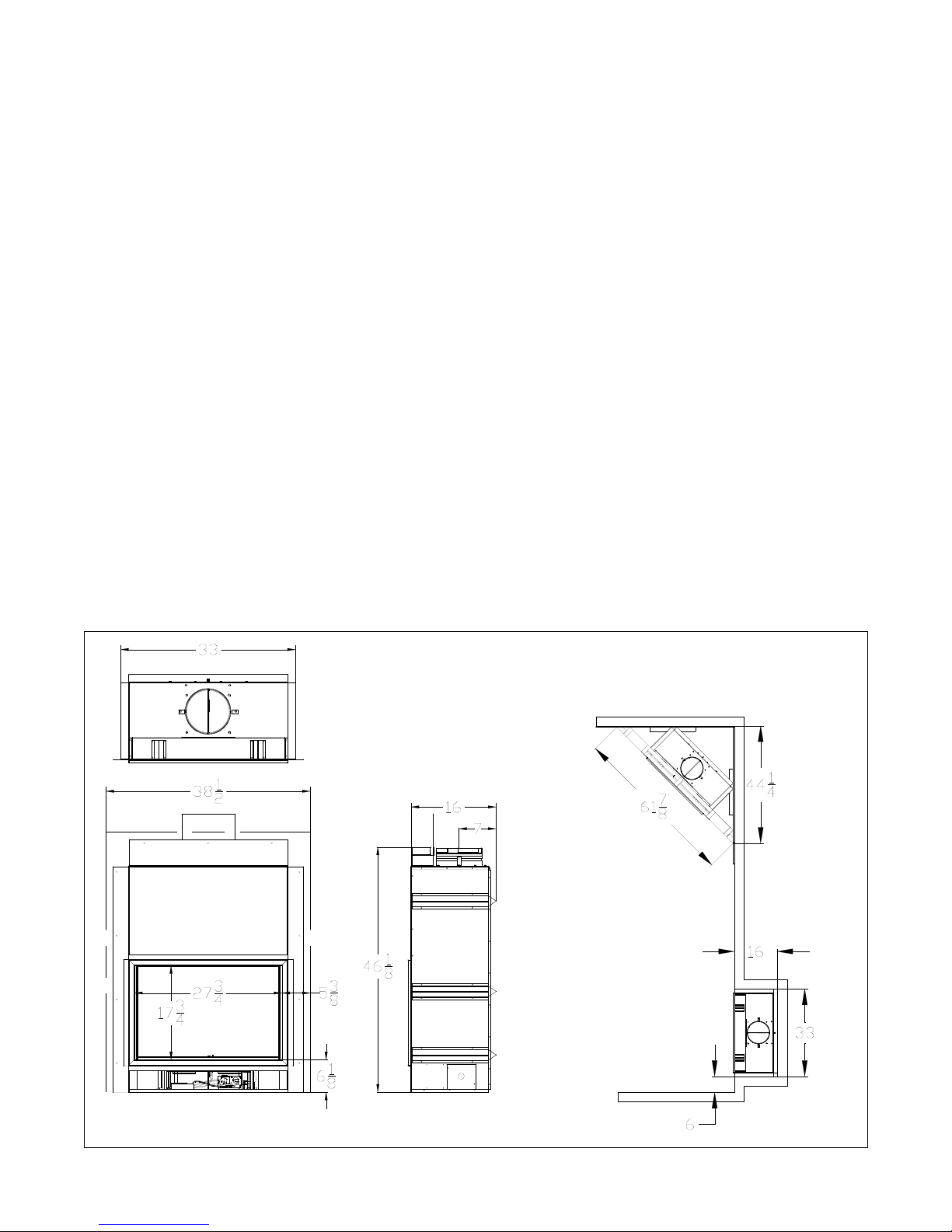
SPECIFICATIONS and DIMENSIONS
Natural Gas Propane (LP)
Manifold Pressure: 4.0” (1.0 kPa) 10.0” ( 2.5 kPa)
Maximum Supply Pressure: 7.0” (1.7 kPa) 13.0” (3.2 kPa)
Minimum Supply Pressure: 4.0” (1.0 kPa) 11.0” (2.7 kPa)
Orice Size: 6 Port #55 DMS #48 DMS
Canadian Eciency P.4: 32% 39%
Input: High Fire 42,000 BTU/hr. 43,500 BTU/hr.
Low Fire* 27,000 BTU/hr. 27,000 BTU/hr.
*VBM burner ONLY
VBM Wall Adapter Specications
Input Voltage: 120V AC
Input Power: 9 W
Output Voltage: 6V DC
Output Current: 500 mA
Size: 3.1”H x 2”W x 1.7”D
Output Cord Length: 6 Feet
Agency Approvals: UL, CSA
All dimensions are in inches.
24VBM Electrical Rating
Voltage: 120V AC, 60 Hz
Current: 0.8A
Agency Approvals: CSA
8
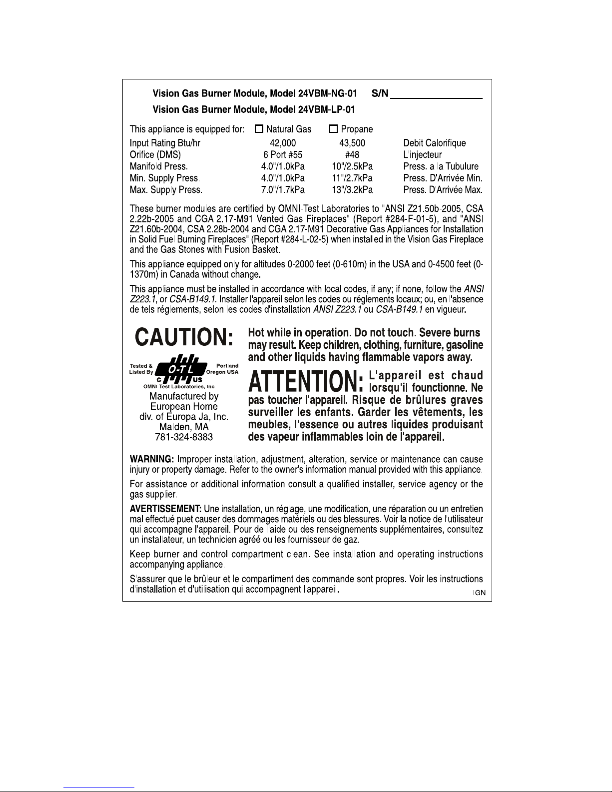
Vision Gas Burner Module, Model VBM-NG-02
Vision Gas Burner Module, Model VBM-LP-02
This appliance is equipped for: Natural Gas/Gaz Naturel Propane Cet appareil est équipé pour:
Input Rating Btu/hr 42,000 43,500 Debit Calorifique
Min. Input (Btu/hr) 27,000 27,000 Puissance Minimum
Orifice (DMS) 6 Port #55 #48 L'injecteur
Manifold Press. 4.0"/1.0kPa 10"/2.5kPa Press. a la Tubulure
Min. Supply Press. 4.0"/1.0kPa 11"/2.7kPa Press. D'Arrivée Min.
Max. Supply Press. 7.0"/1.7kPa 13"/3.2kPa Press. D'Arrivée Max.
These burner modules are certified by OMNI-Test Laboratories to “ANSI Z21.50b-2005, CSA 2.22b-2005 and CGA 2.17-M91 Vented
Gas Fireplaces” when installed in the Vision Gas Fireplace (Report #284-F-01-5) and “ANSI Z21.60b-2004, CSA 2.28b-2004 and
CGA 2.17-M91 Decorative Gas Appliances for Installation in Solid Fuel Burning Fireplaces” when installed in the Gas Stones
with Fusion Basket (Report #284-L-02c-5).
Ces modules de brûleur sont certifiés par les laboratoires OMNI-Test (OMNI-Test Laboratories) conformes aux normes “ANSI
Z21.50b-2005, CSA 2.22b-2005 et CGA 2.17-M91 pour les foyers à gaz ventilés” lorsqu’ils sont installés dans le foyer à gaz Vision
(Rapport #284-F-01-5) et conformes aux normes “ANSI Z21.60b-2004, CSA 2.28b-2004 et CGA 2.17-M91 pour les appareil à gaz
décoratifs pour une installation dans les foyers alimentés au combustible solide” lorsqu’ils sont installés dans le foyer Gas
Stones with Fusion Basket (Rapport #284-L-02c-5).
This appliance equipped only for altitudes 0-2000 feet (0-610m) in the USA and 0-4500 feet (0-1370m) in Canada without change.
Cet appareil n’est équipé que pour les altitudes de 0 à 610 m (0 à 2000 pi) aux États-Unis et 0 à 1370 m (0 à 4500 pi) au Canada
sans modification.
This appliance must be installed in accordance with local codes, if any; if none, follow the ANSI Z223.1, or CSA-B149.1. Installer
l'appareil selon les codes ou réglements locaux; ou, en l'absence de tels réglements, selon les codes d'installation ANSI Z223.1
ou CSA-B149.1 en vigueur.
S/N
CAUTION:
Vision Gas Fireplace
Report #284-F-01-5
Gas Stones with Fusion Basket
Report #284-L-02c-5
Manufactured by
European Home
376 Washington Street
Malden, MA 02148
tel: (781) 324-8383
WARNING: Improper installation, adjustment, alteration, service or maintenance can cause injury or property damage. Refer to the owner's
information
the gas supplier.
AVERTISSEMENT: Une installation, un réglage, une modification, une réparation ou un entretien mal effectué puet causer des dommages
matériels ou des blessures. Voir la notice de l'utilisateur qui accompagne l'appareil. Pour de l'aide ou des renseignements supplémentaires,
consultez un installateur, un technicien agréé ou les fournisseur de gaz.
Keep burner and control compartment clean. See installation and operating instructions accompanying appliance.
S'assurer que le brûleur et le compartiment des commande sont propres. Voir les instructions d'installation et d'utilisation qui accompagnent
l'appareil.
manual provided with this appliance. For assistance or additional information consult a qualified installer, service agency or
may result. Keep children, clothing, furniture, gasoline and other liquids
having flammable vapors away.
ATTENTION:
pas toucher l'appareil. Risque de brûlures graves surveiller les enfants. Garder
les vêtements, les meubles, l'essence ou autres liquides produisant des
vapeur inflammables loin de l'appareil.
Hot while in operation. Do not touch. Severe burns
L'appareil est chaud lorsqu'il founctionne. Ne
IGN
Vision Gas Fireplace Listing Label for VBM Burner
9
Vision Gas Fireplace Listing Label for 24VBM Burner
10
WARNING
Label all wires prior to disconnection when servicing controls. Wiring errors can cause improper and dangerous
operation.
This appliance must be electrically grounded in accordance with local codes, or, in the absence of local codes, with either
the National Electrical Code ANSI/NFPA 70, for installations in the U.S. or the Canadian Electrical Code, CSA C22. 1 for
installations in Canada.
Electrical work should only be performed by a qualied, licensed electrician. Electric power must be o when making
connections or performing any service.
All wiring shall be in compliance with all local, city, and state codes.
ELECTRICAL REQUIREMENTS
VBM Burner
The Vision Gas Fireplace with a VBM burner uses a receiver and remote control for its burner operation. The remote control comes with a 9V battery and the receiver is powered by a 120V AC wall
adapter.
This installation must provide an approved 120V AC wall receptacle to be placed within the six foot
cord limit of the wall adapter.
The receiver should be powered by either the wall adapter or 4AA batteries - not both. Batteries do
not provide an electrical backup for the wall adapter. Using batteries in combination with the
wall adapter can damage the receiver.
24VBM Burner
The Vision Gas Fireplace with a 24VBM burner is powered by a 24V AC transformer (included) which
must be wired to a 120V AC branch circuit. The 24V AC side of the transformer is switched with a
customer-supplied, 24V AC-rated switch.
11
INSTALLATION CLEARANCES
Several issues must be addressed when selecting a suitable location for the Vision Gas Fireplace.
Observing the required clearances to combustible materials, the accessibility of the gas supply and the
routing of the gas vent must all be considered.
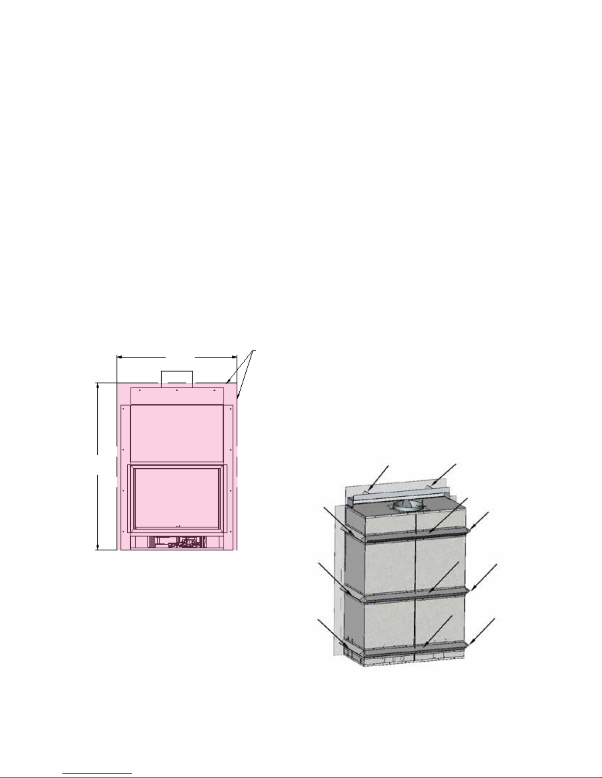
The following clearances to combustible materials must be observed:
• Combustible facing material must not be used within the shaded area shown in Figure 1.
• Combustible materials must not be located inside the areas dened by the standos in Figure 2.
Also see Figure 7 in the FRAMING section.
• Mantels may be installed provided the top of the mantel is not higher than the combustible limit.
If a mantel is required above the combustible limit then non-combustible facing must be used up
to the top of the mantel.
• Combustible wooden mantels may be installed according to the limits shown in the MANTEL
CLEARANCES section.
NO combustible facing
38½”
material allowed inside
shaded area
49”
Standos shown by arrows
Figure 1
Figure 2
12
10.0”
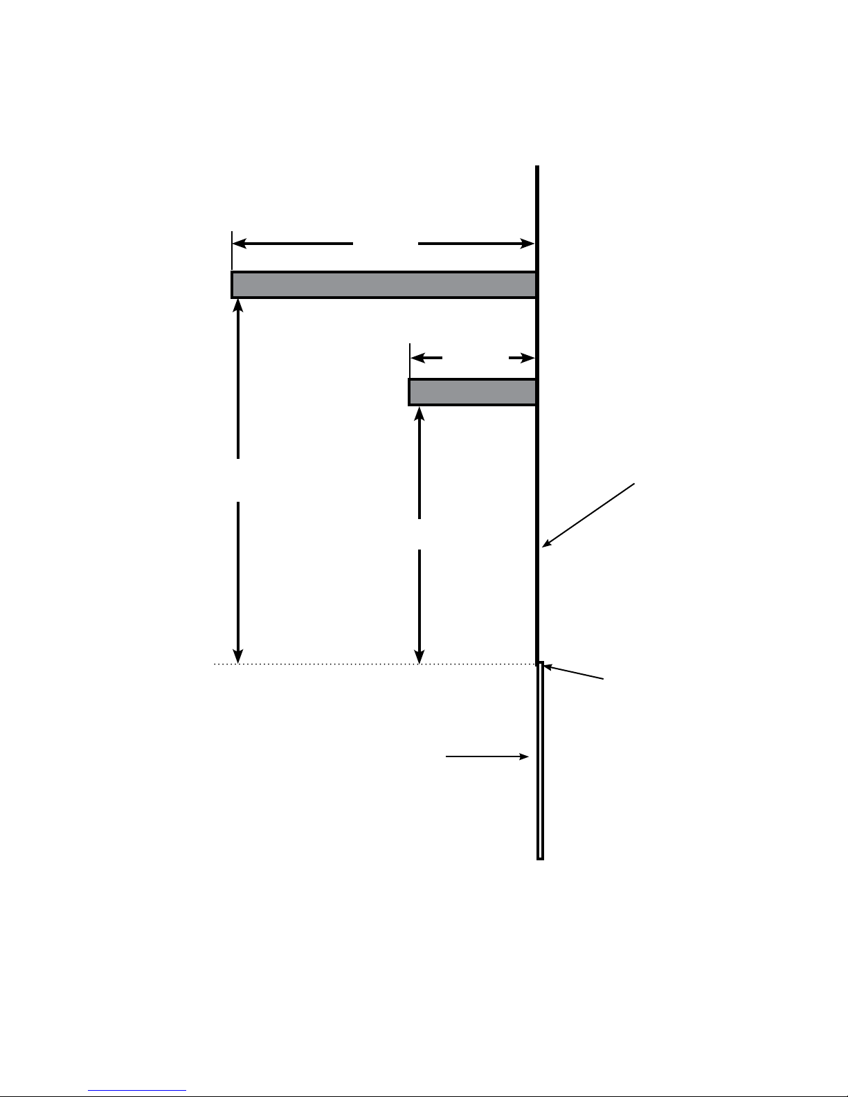
MANTEL CLEARANCES
12.0”
5.0”
NON-combustible
wall facing
8.0”
Top of Vision Gas
Fireplace opening
Vision Gas
Fireplace
opening
Figure 3a
Combustible mantels may be placed no closer to the Vision Gas Fireplace opening than the distances
shown in the Figure 3a side view, above.
13
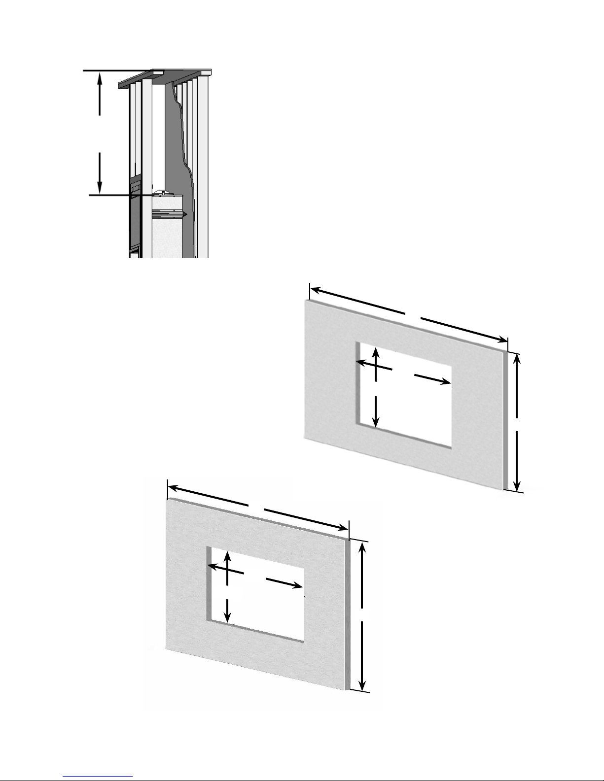
35½”
Figure 3b
The replace may be raised o the oor provided
the top of the replace is no closer to the top of the
chase, or ceiling, than 35½ inches as shown in Figure
3b.
The optional surrounds have an air slot in the
bottom edge. The bottom of the surround
must be 1” above the oor or any carpet.
The dimensions of the two surrounds are
shown in Figures 4a and 4b.
Consider these dimensions when planning
the installation height of the Vision Gas
Fireplace.
48”
26¼”
167/8”
54”
26¼”
16⁄”
28”
Figure 4a
34”
Figure 4b
14
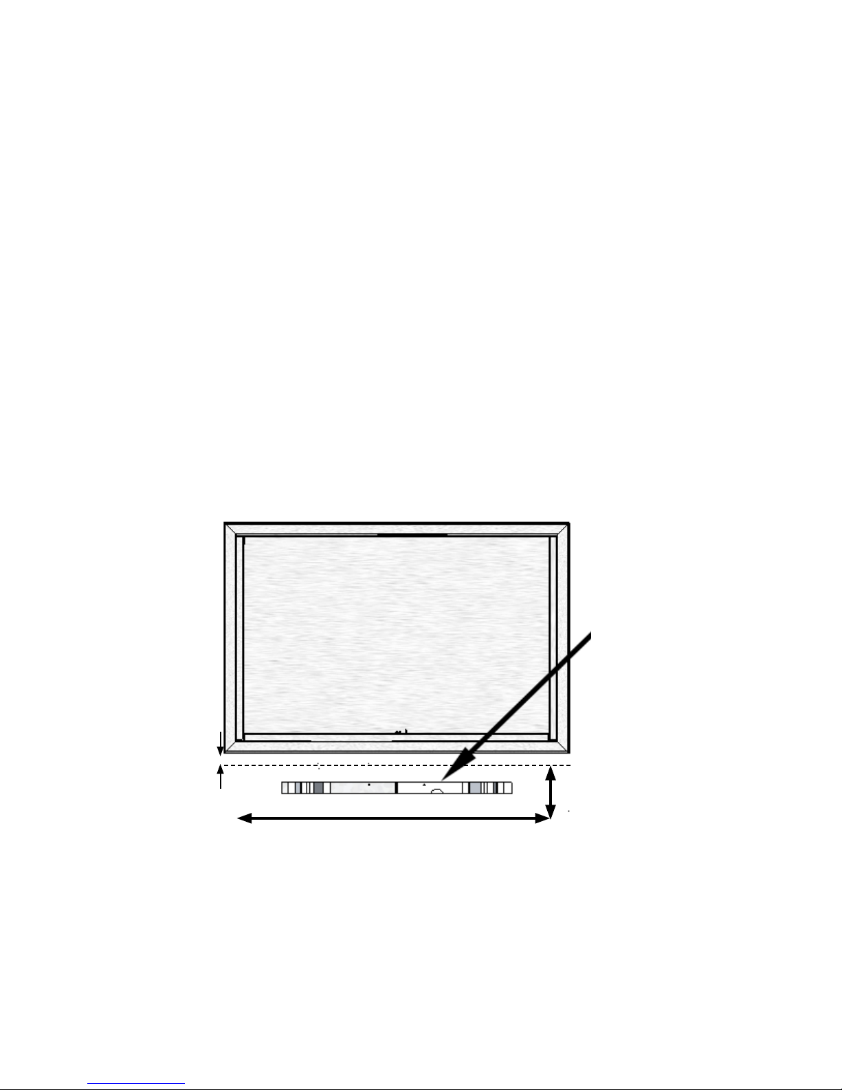
COMBUSTION AIR SUPPLY
In addition to the air that moves through the rebox opening, combustion air MUST also be provided
to the base of the ame in the Vision Gas Fireplace using either one of two methods:
Method 1- When using a European Home Surround
With this method, a minimum twenty square inch opening is cut in the wall face as shown in Figure 5.
When an optional European Home surround is mounted, this combustion air opening is hidden and
air will ow through a cutout in the bottom of the surround.
This combustion air opening should be cut within the 3” by 30” dimensions shown in Figure 5. This 3”
x 30” area begins 1” below the bottom of the lower frame trim.
Figure 5
Combustion
Air Opening
1”
3”
30”
15
 Loading...