

European Home HVF-42, HVF-60, HVF-72, HVF-42-ST, HVF-60-ST Installation, Operation And Owner's Manual
...
H SERIES
Vent · Free · Gas · Fireplaces
Installation,
Operation
and
Owner’s Manual
WARNING: If the information in these
instructions is not followed exactly, a re
or explosion may result causing property
damage, personal injury or loss of life.
-- Do not store or use gasoline or other
ammable vapors and liquids in the vicinity of
this or any other appliance.
WHAT TO DO IF YOU SMELL GAS
• Do not try to light any appliance.
• Do not touch any electrical switch; do
not use any phone in your building.
• Immediately call your gas supplier from
a neighbor’s phone. Follow the gas supplier’s instructions.
Models:
HVF-42
HVF-60
HVF-72
This is an unvented gas-red heater. It
uses air (oxygen) from the room in which
it is installed. Provisions for adequate
combustion and ventilating air must be
provided. Refer to page 6.
This appliance may be installed in an
aftermarket, permanently located,
manufactured (mobile) home, where not
prohibited by local codes.
This appliance is only for use with the type
of gas indicated on the rating plate. This
appliance is not convertible for use with
other gases.
• If you cannot reach your gas supplier,
call the re department.
-- Installation and service must be performed
by a qualied installer, service agency or the
gas supplier.
H Series Vent Free Gas Fireplace EuropeanHome.com
INSTALLER: Leave this manual with the
appliance.
CONSUMER: Retain this manual for future
reference.
February 2014
Report #284-F-07-5
1

TABLE OF CONTENTS
Important Safety Information 3
Room Volume for Vent Free 6
Specications and Dimensions 8
Pre-installation Planning 10
Rough Installation 15
Electric Installation 16
Gas Installation 18
Trim and Finish 19
Operating the Fireplace 21
Maintenance 23
Parts List 24
Warranty 26
Troubleshooting Appendix One
H Series Vent Free Gas Fireplace EuropeanHome.com
2

IMPORTANT SAFETY INFORMATION
Read these instructions carefully before installing or trying to operate this Vent Free gas heater.
PRODUCT INSTALLATION RECORD
Installer: Please complete this form. Customer: Please retain this information.
Purchased From
Date of Purchase
Installed By
Date of Installation
Fireplace Serial Number
Fuel Type NATURAL GAS
• Any change to this heater or its controls can be dangerous.
• Improper installation or use of the heater can cause serious injury or death
from re, burns, explosion or carbon monoxide poisoning.
• Do not allow fans to blow directly into the replace. Avoid any drafts that alter
burner ame patterns.
WARNING
• Do not use a blower insert, heat exchanger insert or other accessory, not
approved for use with this heater.
1. Due to high temperatures, the heater should be located out of trac and away from furniture and
draperies.
2. Children and adults should be alerted to the hazard of high surface temperature and should stay
away to avoid burns or clothing ignition.
3. Young children should be carefully supervised when they are in the same room with the heater.
4. Do not place clothing or other ammable material on or near the heater.
H Series Vent Free Gas Fireplace EuropeanHome.com
3

IMPORTANT SAFETY INFORMATION
Read these instructions carefully before installing or trying to operate this Vent Free gas heater.
5. Any safety screen or guard removed for servicing an appliance, must be replaced prior to operating
the heater.
6. Installation and repair should be done by a qualied service person. The heater should be inspected
before use and at least annually by a professional service person. More frequent cleaning may be
required due to extensive lint from carpeting, bedding material, etc. It is imperative that control
compartments, burners and circulating air passageways of the heater be kept clean.
7. To prevent malfunction and/or sooting, an unvented gas heater should be cleaned before use and at
least annually by a professional service person.
8. CARBON MONOXIDE POISONING: Early signs of carbon monoxide poisoning are similar to the u
with headaches, dizziness and/or nausea. If you have these signs, obtain fresh air immediately. Have
the heater serviced as it may not be operating properly.
9. The installation must conform with local codes or, in the absence of local codes, with the National
Fuel Gas Code, ANSI Z223.l/NFPA54.
10. This unit was tested and listed to ANSI Z21.11.2-2011 by OMNI-Test Laboratories.
11. This appliance is approved for installation in the Commonwealth of Massachusetts. The Board of State
Examiners of Plumbers and Gas Fitters has issued approval number G1-0513-436 for this appliance.
12. Do not install this heater in a bathroom or bedroom.
13. Correct installation of the re media, proper location of the heater, and annual cleaning are
necessary to avoid potential problems with sooting. Sooting, resulting from improper installation or
operation, can settle on surfaces outside the replace. See media placement instructions for proper
installation.
14. WARNING: Avoid any drafts that alter burner ame patterns. Do not allow fans to blow directly into
replace. Do not place a blower inside burn area of rebox. Ceiling fans may create drafts that alter
burner ame patterns. Sooting and improper burning will occur.
15. Caution: Candles, incense, oil lamps, etc. produce combustion by-products including soot. Vent
Free heaters will not lter or clean soot produced by these types of products. In addition, the smoke
and/or aromatics (scents) may be reburned in the vent free heater which can produce odors. It is
recommended to minimize the use of candles, incense, etc. while the vent free heater is in operation.
H Series Vent Free Gas Fireplace EuropeanHome.com
4

IMPORTANT SAFETY INFORMATION
Read these instructions carefully before installing or trying to operate this Vent Free gas heater.
16. Keep room area clear and free from combustible materials, gasoline and other ammable vapors and
liquids.
17. This appliance is intended for supplemental heating.
18. Unvented gas heaters emit moisture into the living area. In most homes of average construction,
this does not pose a problem. In houses of extremely tight construction, additional mechanical
ventilation is recommended.
19. During manufacturing, fabricating and shipping, various components of this heater are treated with
certain oils, lms or bonding agents. These chemicals are not harmful but may produce annoying
smoke and smells as they are burned o during the initial operation of the heater; possibly causing
headaches or eye or lung irritation. This is a normal and temporary occurrence. The initial break-in
operation should last two to three hours with the burner at the highest setting. Provide maximum
ventilation by opening windows or doors to allow odors to dissipate. Any odors remaining after this
initial break-in period will be slight and will disappear with continued use.
20. Input ratings are shown in BTU per hour and are for elevations up to 2,000 feet. If your installation
is at an elevation greater than these, consult with the local authority having jurisdiction for gas
product installations to determine their specic requirements for high altitude installations.
21. The heater must be isolated from the gas supply piping system by closing its equipment shuto
valve during any pressure testing of the gas supply piping system at test pressures equal to or less
than ½ psi (3.5 kPa).
22. Do not use this room heater if any part has been under water. Immediately call a qualied service
technician to inspect the heater and to replace any part of the control system and any gas control
which has been under water.
23. Never burn solid fuels in a replace where an unvented heater is installed.
24. WARNING: Any change to this heater or its controls can be dangerous.
25. When this heater is installed directly on carpeting, tile or other combustible material, other than
wood ooring, the heater shall be installed on a metal or wood panel extending the full width and
depth of the heater.
H Series Vent Free Gas Fireplace EuropeanHome.com
5
ROOM VOLUME for VENT FREE
CODES
Adhere to all local codes or, in their absence, the latest edition of THE NATIONAL FUEL GAS CODE ANSI Z223.1 or NFPA54 which
can be obtained from…
American National Standards Institute, Inc.
1430 Broadway
New York, NY 10018
or
National Fire Protection Association, Inc.
Batterymarch Park
Quincy, MA 02269
ADEQUATE COMBUSTION AND VENTILATION AIR
This heater shall not be installed in a conned space or unusually tight construction unless provisions are provided for adequate
combustion and ventilation air.
The National Fuel Gas Code, (ANSI Z223.1/NFPA 54), denes a conned space as a space whose volume is less than 50 cubic feet
per 1,000 BTU per hour (4.8 m3 per kw) of the aggregate input rating of all appliances installed in that space. An unconned space
is dened as a space whose volume is not less than 50 cubic feet per 1,000 BTU per hour (4.8 m3 per kw) of the aggregate input
rating of all appliances installed in that space. Rooms communicating directly with the space in which the appliances are installed,
through openings not furnished with doors, are considered a part of the unconned space.
UNUSUALLY TIGHT CONSTRUCTION IS DEFINED AS CONSTRUCTION WHERE…
a) walls and ceilings exposed to the outside atmosphere have a continuous water vapor retarder with a rating of 1 perm (6 x
1011 kg per pa-sec-m2) or less with openings gasketed or sealed;
b) weather stripping has been added on operable windows and doors, and
c) caulking or sealants are applied to areas such as joints around window and door frames, between sole plates and oors,
between wall-ceiling joints, between wall panels, at penetrations for plumbing, electrical, and gas lines, and at other openings.
This appliance is equipped for natural gas. Field conversion is not permitted.
WARNING
This heater shall not be installed in a room or space unless the required volume
of indoor combustion air is provided by the method described in the National
Fuel Gas Code, ANSI Z223.1/NFPA 54, the International Fuel Gas Code, or
WARNING
applicable local codes.
H Series Vent Free Gas Fireplace EuropeanHome.com
6
ROOM VOLUME for VENT FREE
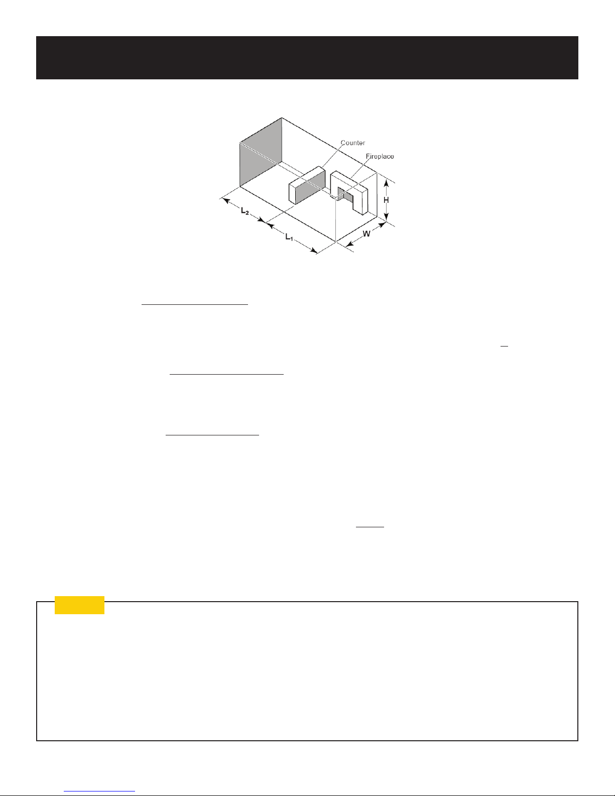
The following formula can be used to determine the maximum heater rating (per the denition of unconned space) that is allowed in your space:
Maximum BTU/Hr. = x 1000
Example A: Consider two connecting rooms with an open area between, with the following dimensions: L1 = 15½ ft., L2 = 12 ft., W
= 12 ft., H = 8 ft.
x 1000 = 52,800 BTU/Hr.
Example B: If there were a door between the two rooms the calculation would be based only on the room with the heater.
x 1000 = 29,760 BTU/Hr.
Will my space support a H Series Vent Free Gas Fireplace?
Maximum BTU/hr. my space will support (use formula above) a) __________________
BTU/hr. of European Home H Series Vent Free Gas Fireplace b) ____37,500________
If the answer to a) is greater than b) then your space will support the installation of the H Series Vent Free Gas Fireplace; if a) is
less than b) then your space will not support an H Series Vent Free replace.
(L1 + L2)ft. x (W)ft. x (H)ft.
50
(15½ + 12)ft. x (12)ft. x (8)ft.
50
(15½)ft. x (12)ft. x (8)ft.
50
Note
Bringing in Outside (or “Make-up”) Air
Many building code jurisdictions require that outside or “make-up” air be provided when installing a replace of this type. This
requirement can be satised by the proper installation of an ‘outside air kit’ which is not provided. The nal determination of the
suitability of any particular kit must be made by the installer.
If an outside air supply is desired it should be added to the room in which the H Series Vent Free Gas Fireplace is installed, not to
the chase enclosing the replace.
If outside air is introduced into the chase, competing air pressures could compromise the operation of the replace.
H Series Vent Free Gas Fireplace EuropeanHome.com
7
26⁄”
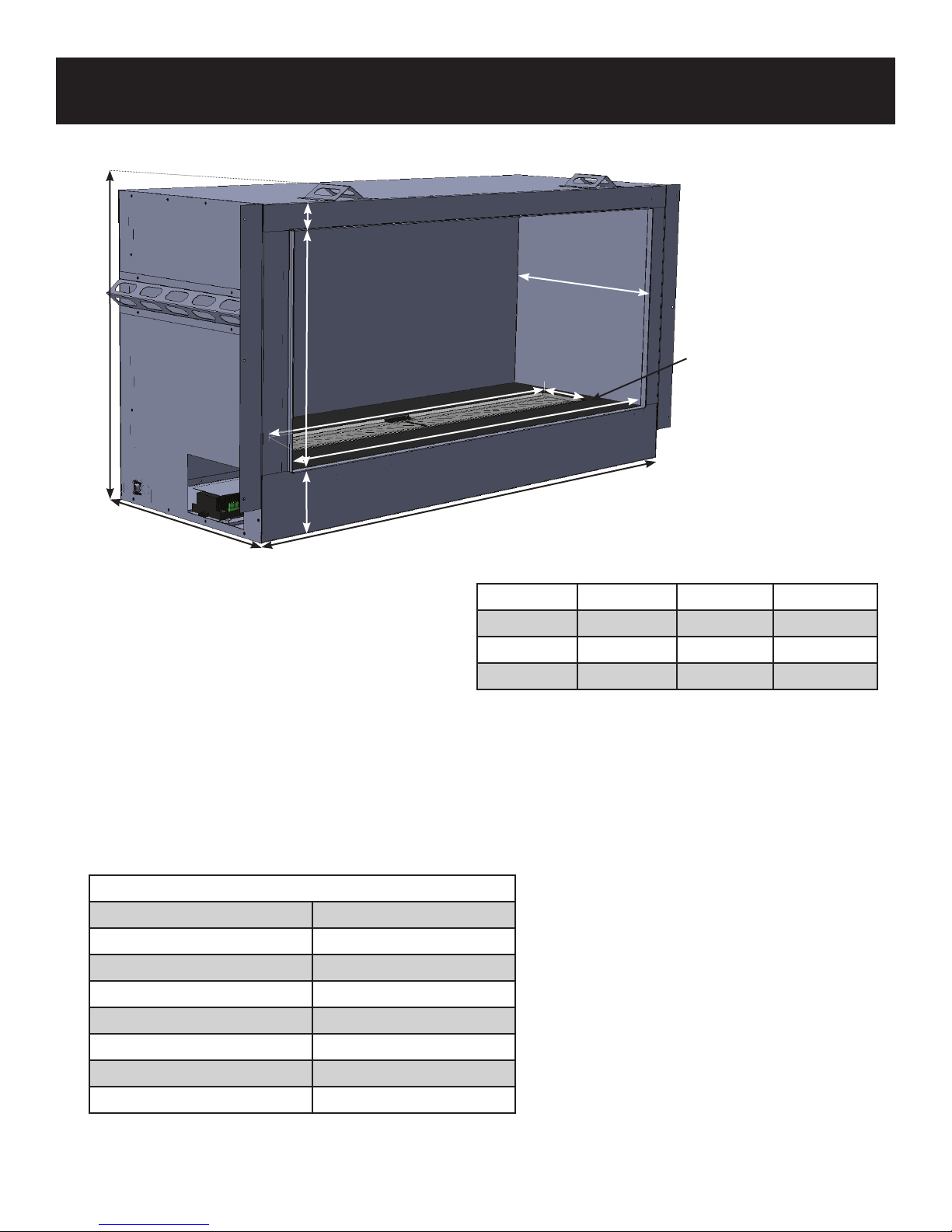
SPECIFICATIONS and DIMENSIONS
2”
15½”
18”
5”
18”
Hearth Panel
(lifts o for service, all models)
5”
C
B
A
Figure 1. HVF-42, HVF-60, HVF-72 Fireplaces
Dimension HVF-42 HVF-60 HVF-72
A 47” 65” 77”
B 42” 60” 72”
C 38” 49” 59”
Table 1. Dimensions by Model
H Series Burner
Fuel Natural Gas ONLY
Manifold Pressure 3.5” (0.87 kPa)
Minimum Supply Pressure 4.0” (1.0 kPa)
Maximum Supply Pressure 7.0” (1.7 kPa)
Orice Size #47 DMS
Input (High, BTU/hr.) 37,500
Input (Low, BTU/hr.) 25,000
Electrical 120V AC 60Hz 2.5A max
Table 2. Burner Specications
H Series Vent Free Gas Fireplace EuropeanHome.com
8

SPECIFICATIONS and DIMENSIONS
CERTIFICATION
OMNI-Test Laboratories, Inc. has certied that the H Series Gas Fireplaces meet the ANSI Z21.11.2-2011
standard.
These appliances are approved for installation in the Commonwealth of Massachusetts. The Board of State
Examiners of Plumbers and Gas Fitters has issued approval number G1-0513-436 for these appliances.
H Series VENT FREE GAS FIREPLACE
Model: HVF -72HVF-60HVF-42
Serial Number: HVFS-
Max. Input BTU/hr.: 37,500
Min. Input BTU/hr.: 25,000
Max. Supply Pressure: 7 inches w.c.
Min. Supply Pressure: 4 inches w.c.
Max. Manifold Pressure: 3.5 inch w.c.
Top: 1.0” Wall face above opening: 4.0”
Rear: 0.0” Opening to side wall in front of appliance: 6.0”
Sides: 1.0” Mantel to appliance opening: 11.0”
Maximum horizontal mantel extension: 12.0”
This product has been certie d by OMNI-Test Laboratories to ANSI Z21.11.2b-2011
Unvented Heaters. This appliance must be installed in accordance with l ocal codes,
if any; if none, follow the ANSI Z223.1. Installation and service must be must be
performed by a qualied install er, service agency or the gas supplier.
This appliance shall not be eld converted.
WARNING: Do not use a blower insert, heat exchanger inser t or other accessory not
approved for use with this heater.
WARNING: Improper installation, adjustment, alteration , service or maintenance can
cause property damage, per sonal injury or loss of life. Refer to the owner’s information
manual provided with this appliance. Installation and ser vice must be performed by a
qualied installer, service agency or the gas sup plier.
This heater shall not be installed in a bedroom or b athroom.
This appliance is intended for supplemental heating.
Failure to use only parts specically approved with this heater m ay result in property
damage or personal injury. See instructi on manual for further information.
Apply loose material per instruction m anual. DO NOT apply extra material or material
not supplied with the heater. Replace only with European Home Fire Med ia approved
for H Series VENT FREE Fireplaces.
WARNING: All previously applied loose material must be removed prior to reapplication.
This appliance is equipped for Natural Gas only.
MINIMUM CLEARANCES TO COMBUSTIBLE MATERIALS
Left and Right side are determined when facing the front of the appliance.
Orice Size: #47 DM S
Gas Control: SIT Pro ame
Electrical Rating: 120v AC, 60 Hz
2.5 A
SAMPLE
Figure 2. Sample Rating Label (axed beneath the Hearth Panel
CAUTION: Hot while in operation. Do not touch.
Severe burns may result. Keep children, clothing, furniture,
gasoline and other liquids having ammable vapors away.
WARNING: When used without adequate combustion
and ventilation air, heater may give o excessive CARBON
MONOXIDE, an odorless, poisonous gas.
DO NOT INSTALL HEATER UNTIL ALL NECESSARY PROVISIONS ARE MA DE FOR
COMBUSTION AND VENTILATION AIR . CONSULT THE WRITTEN INSTRUCTIONS
PROVIDED WITH THE HEATER FOR INFORMATION CONCE RNING COMBUSTION
AND VENTILATION AIR. IN THE ABS ENCE OF INSTRUCTIONS, RE FER TO THE
NATIONAL FUEL GAS CODE, ANSI Z223.1/NFPA 54, AIR FOR COMBUSTION AND
VENTILATION, OR APPLICABLE LOCAL CODES.
This heater is equipp ed with a PILOT LIGHT SAFETY SYSTEM desig ned to turn o
the heater if not enou gh fresh air is available.
DO NOT TAMPER WITH THE PILOT LIGHT SAFETY SYSTEM!
If heater shuts o, do not relight until you provide fresh air. If heater keeps
shutting o, have it serviced. Keep burner and control compartment clean.
CARBON MONOXIDE POISONING MAY LEAD TO DEATH.
Early signs of carbon monoxide poisoning resemble the ue, with headache,
dizziness and/or nausea. If you have these signs, heater may not be working
properly.
Get fresh air at once! Have heater serviced.
Some people – pregnant women, persons with heart or lung disease, anemia,
those under the inuence of alcohol, those at high altitudes – are more aected
by carbon monoxide than others.
Removal of this marking will void compliance of this heater with ANSI Z21.11.2.
manufactured by:
EUROPEAN HOME
376 Washington Street
Malden, MA 02148
Report Number: 284-F-07-5
HVFS1SLL130424
tel: (781) 324-8383
www.europeanhome.com
H Series Vent Free Gas Fireplace EuropeanHome.com
9

PRE-INSTALLATION PLANNING
WHEN ENCLOSING YOUR FIREPLACE THE USE OF NON-COMBUSTIBLE BUILDING MATERIALS
IS REQUIRED. PLEASE READ AND UNDERSTAND THE FOLLOWING.
COMBUSTIBLE MATERIALS
Materials that can catch re and burn are considered combustible. Any material that is made of, or faced
with, wood, wood pulp, paper, plastic or any other material that can catch re and burn is considered combustible. Even though these materials may have been 'ame-proofed', made 're-resistant' or are 're-rated'
they are considered combustible. Standard and Type X drywall are both combustible.
NONCOMBUSTIBLE MATERIALS
A given material is said to be non-combustible when it cannot catch re and burn. For example, materials
made entirely, or in combinations, of, stone, brick, concrete, tile, steel, plaster or glass are considered noncombustible.
See the chart below for a list of materials which, as of this writing, are reported by their manufacturers to be
BOTH non-combustible (in accordance with the ASTM E136 standard) AND approved for use around replaces.
Product* Non-combustible Manufacturer Approved
James Hardie Building Products HardieBacker® ¼” Cement Board YES YES
James Hardie Building Products HardieBacker® 500 Cement Board YES YES
Promat PROMATECT®-L Insulating Boards YES YES
Skamol Skamotec® 225 YES YES
U.S. Architectural Products Versaroc® Cement Bonded Particle Board YES YES
U.S. Architectural Products Cem-Clad® Cement Panel YES YES
National Gypsum PermaBase® Cement Board NO NO
USG DUROCK® Cement Board Next Gen YES NO
CertainTeed Fiber Cement BackerBoard NO NO
Custom Building Products WonderBoard® Backerboard NO NO
Georgia-Pacic Gypsum DensGlass® Sheathing YES NO
Ameriform ARMOROC® Cement Bonded Particle Board YES NO
HIGH ALTITUDE INSTALLATIONS
These appliances are tested and approved without requiring changes when installed at elevations from 0 to
2,000 feet.
When installing these replaces at altitudes above 2,000 feet reduce the input rate by 4% for each 1,000
above 2,000 feet. Consult with your local gas supplier to determine the proper orice size.
ELECTRICAL CODE
The H Series Gas Fireplace, when installed, must be electrically grounded in accordance with local codes, or,
in the absence of local codes, with the National Electrical Code ANSI/NFPA 70.
H Series Vent Free Gas Fireplace EuropeanHome.com
10

PRE-INSTALLATION PLANNING
BEFORE YOU BEGIN
Thank you for purchasing an H Series Gas Fireplace by European Home. This replace has been designed to
provide you with safe, trouble-free operation.
Please read this manual thoroughly before beginning the installation of your replace. It has information
which is important for safe installation and operation.
Please inspect your shipment for completeness and any damage. Contact your retailer if any damage is
found. Do not install your replace with any damaged or substituted parts.
The installation of your new replace will follow the steps below and this manual is laid out accordingly.
• Pre-Installation Planning - Fireplace location, gas and electric supply runs and clearances
• Rough Installation - Build the rough frame and install the replace
• Electric Installation - By a qualied, licensed electrician
• Gas Installation- By a qualied, licensed gastter or plumber
• Trim and Finish - Finishing around the replace
• Final Installation - Wall, mantel and non-combustible facing
Before you begin your installation you should have
the following tools and supplies:
• Saw
• Hammer
• Pliers
• Pipe wrench
• Phillips and straight-blade screwdrivers
• Plumb line and level
• Tape measure and framing square
• Electric drill and assortment of drill bits
• Safety glasses and gloves
• Framing material
• Non-combustible nish material
• Approved pipe joint sealant
• Manometer
• #6 or #8 self-tapping screws, ½” ¾” long
• Leak detection uid (non-corrosive) or electronic
gas detector
• Appropriate electrical supply wiring parts
• Appropriate gas supply line parts
H Series Vent Free Gas Fireplace EuropeanHome.com
11

PRE-INSTALLATION PLANNING
6” min.*
6” min.*
6” min.*
Figure 3. Possible Fireplace Locations..
LOCATING THE FIREPLACE
Several issues must be addressed when selecting a suitable location for the H Series Vent Free Gas Fireplace.
Observing the required clearances to combustible materials, the accessibility of the gas supply as well as the
room into which it will be installed must all be considered.
This appliance is a HEATING appliance
and it becomes hot in operation. DO NOT
PLACE any object, furniture, draperies or
other item LESS THAN 36 inches from the
front of the replace.
The clearance dimensions shown
throughout this manual MUST be
maintained for safety as well as servicing
and maintenance.
36"
36"
90cm
90cm
36”
42” - 72”
(depends on model)
36"
90cm
36"
90cm
36"
H Series Fireplace
36"
6” min.*
90cm
90cm
H Series Vent Free Gas Fireplace EuropeanHome.com
Do not put furniture or
other objects in this space
in front of the fireplace.
Figure 4. Clearances to Objects
12

PRE-INSTALLATION PLANNING
MINIMUM MANTEL and ENCLOSING CLEARANCES
Figure 5. Mantel, Ceiling and Enclosure Clearances
(right side view, not to scale)
Combustible Wall
Face
36”
Room Ceiling
Top Line of
Fireplace
Opening
23⁄”
11”
Combustible
Enclosing
Ceiling
12”
NON-COMBUSTIBLE
Wall Face
4”
26¾”
Fireplace
Opening
H Series Vent Free Gas Fireplace EuropeanHome.com
13

PRE-INSTALLATION PLANNING
When enclosing your replace, the use of non-combustible building materials
is required. Please read and understand the COMBUSTIBLE MATERIALS and
NON-COMBUSTIBLE MATERIALS sections on page 10.
MINIMUM CLEARANCES TO COMBUSTIBLE MATERIALS
When installing the H Series Fireplaces, the clearances shown in the table below must be observed. If the
required clearances are not maintained a re may result thereby causing property damage, personal injury
or loss of life.
When the replace is to be installed directly on carpeting, vinyl tile or combustible material other than wood
ooring, it must be installed on a metal or wood panel extending the full width and depth of the replace
cabinet.
HVF-42
MINIMUM CLEARANCES TO COMBUSTIBLE MATERIALS
HVF-60
HVF-72
Clearance to Cabinet Top 1.0”
Clearance to Cabinet Sides 1.0”
Clearance to Cabinet Rear 0”
Clearance to Wood Floor 0”
Distance Between Cabinet Bottom and Enclosure Ceiling 26¾”
Distance Between the Opening and a Side Wall in Front of the Fireplace 6.0”
Table 3. Minimum Clearances to Combustible Materials
H Series Vent Free Gas Fireplace EuropeanHome.com
14

ROUGH OPENING
ROUGH INSTALLATION
Dimension HVF-42 HVF-60 HVF-72
A (Width) 49¾” 67¾” 79¾”
B (Height) 26¾” 26¾” 26¾”
C (Depth) 18½” 18½” 18½”
Table 4. Rough Opening Dimensions by Model
B
A
C
Figure 6. Rough Opening for HVF-42, HVF-60, HVF-72
INSTALLING THE FIREPLACE
The H Series replaces must be placed on a sturdy and level surface. It can be placed on the oor or a raised
platform made ONLY of wood or non-combustible materials - do not place the replace on carpet or vinyl
tile.
1. After the framing has been completed, place the replace into the rough opening. Framing material can
touch the standos at the sides and rear of the cabinet but do not place anything between the framing
and the standos.
2. Make sure the replace is both level and square.
3. Secure the replace to the framing via the nailing anges. Use the fasteners required by your local
building code.
H Series Vent Free Gas Fireplace EuropeanHome.com
15

ELECTRIC INSTALLATION
Caution: Label all wires prior to disconnection when servicing controls. Wiring errors can cause improper
and dangerous operation.
This appliance must be electrically grounded in accordance with local codes, or, in the absence of local
codes, with either the National Electrical Code ANSI/NFPA 70.
Electrical work should only be performed by a qualied, licensed electrician. Electric power must be o
when making connections or performing any service.
All wiring shall be in compliance with all local, city, and state codes.
Verify proper operation after servicing.
ELECTRICAL ASSEMBLY
The H Series replaces require the internal receptacle (supplied) to be wired to a 120V AC branch circuit
according to all applicable codes. The neutral, line and ground wires to the receptacle are available at the
lower left corner of the replace cabinet. This circuit must be wired such that the AC power to the H Series
replace may be turned o by an accessible single-pole switch. This circuit need not be dedicated to the H
Series replace unless required by local codes.
After the internal receptacle is connected and tested, the AC plug from the burner may be plugged in to it.
BATTERY BACKUP
The H Series replaces have a battery backup feature which, after 4 AA batteries are installed, powers the
system in the case of a commercial power loss. The battery case is in the left rear corner of the replace and
can be accessed by lifting o the hearth panel. Remove the battery case cover and insert four AA batteries as
shown in Figure 7.
Figure 7. Battery Case with Batteries
(shown with cover removed)
H Series Vent Free Gas Fireplace EuropeanHome.com
16

ELECTRIC INSTALLATION
Pilot Burner
Gas Valve
IFC Control Module
Figure 8. Connection Diagram
Power Plug
H Series Vent Free Gas Fireplace EuropeanHome.com
17

GAS INSTALLATION
Note
The installation of this replace must conform with local codes or, in the absence of local codes, with the
National Fuel Gas Code, ANSI Z223.1.
The H Series Vent Free Gas Fireplace is shipped from the factory for use with natural gas ONLY.
Conversion to another fuel is NOT permitted.
This product must be installed by a licensed plumber or gastter when installed within the
Commonwealth of Massachusetts.
INSTALL THE GAS SUPPLY
For the HVF-42, HVF-60 and HVF-72 models, a 4⁄” x 7” opening in the lower left side is provided for the gas
supply.
The gas supply piping should have a separate gas shuto valve and a capped, 1/8” pipe tapping upstream of
the valve for the purpose of reading pressure. A service shuto valve must be placed within six feet of the
replace gas control valve.
The gas supply line must terminate with a ½” male are tting.
The replace must be isolated from the gas supply system by closing the service valve during any pressure
testing of the gas supply system at test pressures equal to or less than ½ psi (3.5 kPa). Verify the gas pressure
using the upstream 1/8” pipe tap.
Fireplace
Opening
5½”
2⁄”
4⁄”x7” Opening for HVF-42, HVF-60, HVF-72,
HVF-42-LC, HVF-42-RC Gas Connection
H Series Vent Free Gas Fireplace EuropeanHome.com
Figure 9. Gas Supply Opening On Left Side (see text)
18

TRIM and FINISH
HVF-42, HVF-60 and HVF-72 WALL FACING
A
B
Figure 10. NON-Combustible Facing Dimensions
Dimension HVF-42 HVF-60 HVF-72
A 42” 60” 72”
B 4” 4” 4”
Table 5. NON-Combustible Facing Dimensions
All of the following limits MUST be maintained for installations of the HVF-42, HVF-60 and HVF-72:
• The bottom of the cabinet may be no closer to the room ceiling than 36”.
• The minimum interior height of an enclosing chase is 26¾”.
• Figure 10 shows the combustible facing limit for the H Series Vent Free Gas Fireplaces shown in Table 5,
above. Combustible wall facing is NOT permitted inside this limit. Dimension “A” is measured up from the
top of the replace opening and the “B” dimension is centered on the cabinet.
H Series Vent Free Gas Fireplace EuropeanHome.com
19

TRIM and FINISH
FINISHING THE ENCLOSURE
The H Series Vent Free Gas Fireplaces are designed to be enclosed with common building materials; wood,
drywall, plaster, etc.
• Any combustible mantels must be installed within the limits shown on page 13.
• Provided the required clearances are maintained, the walls that enclose the side and rear of the replace
may be constructed of combustible material. The facing within the limits shown on page 19, however, must
be made of non-combustible material.
• These replaces were designed to be faced with approved ½” thick, non-combustible facing. This noncombustible facing can be installed up to the facing ange which surrounds the replace opening.
• The wall above the replace opening is constantly exposed to elevated temperatures. This must be
considered when choosing any fasteners, paint, mastic, sealant, caulk, etc. for use in this area as materials
may change color or emit an odor when heated. Petroleum-based tile adhesives should be avoided and
thin-set mortar used instead.
INSTALLING THE FIRE MEDIA
Your H Series Vent Free Gas Fireplace comes with two types of re media; crushed glass or crushed stone
(burner media) and Embaglow. First install the burner media then the Embaglow.
The Fire Media
The contents of the bag of re media (crushed glass or crushed stone) should be spread to an even depth
across the entire burner top. Be certain that glass does not come within ¼” of the pilot burner.
Embaglow
Note: Embaglow contains loose metal bers which may be sharp. You are advised to wear gloves while
installing it.
1. Remove the bunch of Embaglow from the package and tease out the bers until they form a very loose,
very light network. Try to ensure that clumps of bers are not formed. A loose network will allow gas to
pass through the bers and ensure the maximum eect.
2. Once the bers are prepared, place them where a glow is required. By raising the height of the bers
above the level of the burner you’ll create a shimmering glow. Ensure that the metal bers are kept away
from the pilot light area as they can prevent ignition of the pilot light.
Although the bers have a long life, they will eventually deteriorate. If this becomes apparent, replacement
Embaglow can be purchased from your local replace retailer or European Home.
H Series Vent Free Gas Fireplace EuropeanHome.com
20

OPERATING the FIREPLACE
The re media must be installed per these instructions. This heater must use only the re media provided
by European Home. An excess amount of re media may adversely aect the performance of the heater.
WARNING: All previously applied loose material must be removed prior to reapplication.
BEFORE THE FIRST FIRE
1. Make sure all construction materials have been removed from inside and around the replace.
2. Conrm that the electrical wiring is properly connected.
3. Check the gas supply for leaks.
4. Conrm the proper placement of the burner media.
THE FIRST FIRE
The rst time you light your H Series Vent Free Gas Fireplace an odor may be given o by the unit. This is
normal and is a result of the ‘burn o’ of the lubricants and sealants used when manufacturing the replace.
We recommend that you open the nearby windows for extra ventilation and operate the replace for at least
four hours.
During this rst re, examine the ame for appearance and quality. Examine the burner media for sooting.
The ames should look like those in Figure 12.
Since it is a metal replace, the heat-up and cool-down cycles may produce some noises caused by the
expansion and contraction of these metals. The premium materials and build quality of your H Series Vent
Free Gas Fireplace will keep these sounds to a minimum.
H Series Vent Free Gas Fireplace EuropeanHome.com
21

OPERATING the FIREPLACE
FOR YOUR SAFETY READ BEFORE LIGHTING
WARNING: If you do not follow these instructions exactly, a re or explosion
may result causing property damage, personal injury or loss of life.
A. This heater is equipped with an ignition device which automatically lights the pilot. Do NOT try to light
the pilot by hand.
B. BEFORE LIGHTING, smell all around the heater area for gas. Be sure to smell next to the oor because
some gas is heavier than air and will settle on the oor.
WHAT TO DO IF YOU SMELL GAS
• Do not try to light any appliance.
• Do not touch any electric switch; do not use any phone in your building.
• Immediately call your gas supplier from a neighbor’s phone. Follow the gas supplier’s instructions.
• If you cannot reach your gas supplier, call the re department.
C. Do not use this heater if any part has been under water. Immediately call a qualied service technician to
inspect the heater and to replace any part of the control system and any gas control which has been under
water.
LIGHTING THE FIRE
1. STOP! Read the safety information above.
2. This appliance is equipped with an ignition device which automatically lights the pilot. Do not try to light the pilot by hand.
ON/OFF
BUTTON
3. Wait ve (5) minutes to clear out any gas. Then smell for gas
including near the oor. If you smell gas, STOP! Follow “B” in the
Safety Information above. If you don’t smell gas, go to the next
step.
4. With the replace o, press the ON/OFF button. A single beep
from the replace will conrm the button press. If the pilot or
ARROW
KEY
burner does not light, go back to Step 3, above.
5. Use the ARROW KEY to adjust the ame height up and down.
TO TURN OFF THE HEATER
1. With the replace on, press the ON/OFF button. A single beep from the replace will conrm the button
press and the replace will turn o.
H Series Vent Free Gas Fireplace EuropeanHome.com
22

MAINTENANCE
A qualied service agency should conduct an annual inspection and maintenance of your H Series Vent
Free Gas Fireplace to keep it running safely. The following procedures should be performed only by a
qualied service person. The gas supply should be turned o whenever a maintenance procedure is
performed. All parts of the replace that are removed for servicing must be replaced prior to operation.
Cleaning the Media and Burner.
With all parts of the replace at room temperature, carefully remove and clean the re media with a soft
bristled brush.
Lift o the hearth panel and clean the burner surface with a brush and clean the rest of the burner module,
including the pilot burner, with a vacuum cleaner. After lifting o the Hearth Panel, ensure that the Primary
Air Openings (shown in Figure 11, at the end of each Burner Inlet Tube) remains free of dust or debris. These
openings may cleaned with a vacuum cleaner or brush.
Figure 11. Burner Close-up
Failure to keep the primary air opening of the burner clean may result in sooting
and property damage.
WARNING
H Series Vent Free Gas Fireplace EuropeanHome.com
Primary Air Openings
Burner Inlet Tubes
23

Figure 12. Normal Flame Pattern
MAINTENANCE
Make a periodic visual inspection of the pilot and main burner ames.
The main burner ames should look similar to those in Figure 12. The pilot
burner ame should look like that in Figure 13.
Figure 13. Normal Pilot Flame Pattern
H Series Vent Free Parts List
ITEM PART NO.
SIT Proame NG Gas Valve HVF-GS-GV-01
SIT Proame Control Module HVF-GS-CM-01
SIT Proame Remote Control HVF-GS-TX-01
H Series NG Pilot Assembly HVF-GS-PA-01
Carrara Pebbles Fire Media E4-STC4
½” Black Glass Fire Media FM-CG-BLK
Fire Pebbles Fire Media FM-PG-DB
Embaglow Fire Media EMBAGLOW-1G
Black Embers Fire Media EMBERS
For replacement parts and customer service, contact:
H Series Vent Free Gas Fireplace EuropeanHome.com
EUROPEAN HOME
+1 (781) 324-8383
24

WARRANTY
H Series Vent Free Gas Fireplace EuropeanHome.com
25

APPENDIX ONE
Remote Not Learning to Receiver
Remote/Receiver Not Synchronized
Begin
Conrm 120V AC connections
Verify proper 120VAC power supply
A. Remove the batteries from battery back up.
B. Attempt to light continuous pilot from switch. If pilot lights or if spark is present we know power is
supplied and we can proceed. If spark or pilot is not present proceed in troubleshooting steps for pilot does not
light. (if you now re-install batteries and the pilot turns on focus would be on main power supply which is ex-
plained later in the guide with voltage readings)
It is possible the integrated fireplace control (IDC) module is in a lockout position. See page 9 on lockout and reset
information.
Begin
Press the Red SW1 button the on the IFC module. You should
hear 3 fast beeps indicating the receiver box is ready to learn the
remote code. Did you hear the beep code?
Yes
Quickly press the ON/OFF power button on the remote control.
You should now hear 4 beeps indicating the receiver has learned
the remotes unique programming code. Did you hear the beep?
Yes
Remote is learned to the receiver and should operate the fireplace.
IFC
No
No
No
Verify the ON/OFF rocker switch is
in the ON position. Attempt learn
sequence again. If no sound/LED
replace IFC module.
Verify batteries are new in remote,
and if so replace remote control.
Proceed to next troubleshooting
tree to verify there is not another
problem

Troubleshooting
APPENDIX ONE
Begin
Does the
pilot
light?
Yes
No
Is the
piezo
sparking?
No
Yes
1. Verify proper power supply throughout system
- See page 154for multimeter images
2. Make sure power switch is in the ON position
3. Verify wires are properly connected to IFC module
4. Make sure system is properly grounded
5. Check electrode positioning to pilot hood. Adjust
as needed. If porcelain is damaged replace igniter
6. Inspect wiring for damage. Replace if necessary
7. If no spark continues, replace IFC board
1. Verify gas supply is ON and gas line is bled to
valve
2. Inspect wires for damage and replace if needed
3. Inspect pilot tube for damage and replace if needed
4. Inspect pilot orifice and clean if necessary
5. Clean any corrosion from pilot assembly for proper
grounding
6. Check continuity of valve coil. (Image on pg 16)
- If no continuity replace valve
8. Verify proper voltage at pilot valve connection
(Image on pg 15)
- If voltage is present and no gas released,
replace valve.
- If no voltage is present, replace IFC board
Is piezo
still
sparking?
No
Pilot look
blue or
lifting off
sensor?
2
Yes
Yes
1. Verify flame sensor is in the pilot flame, adjust
flame as needed
2. Verify flame sensor wire is properly connected to
module and the system is grounded
3. Clean flame sensor rod and any corrosion from
pilot assembly
4. Check porcelain is not cracked on flame sensor. If
cracked replace flame sensor
5. If sparking continues, replace IFC board
1. Verify proper pilot orifice for type of gas is used
2. Verify the unit is properly converted for type of gas
used. Fireplaces ship Natural Gas.
1. Conrm gas type, pressures and connections.
3. Inspect venting is to manufacturers specifications.
4. Vertical rise on horizontal runs, venting within
chimney heights, etc. No

Troubleshooting
APPENDIX ONE
2
Burner
lights when
pilot only
should light
No
Pilot
holds
flame?
Yes
No
Yes
1. Verify transmitter is not powered on or in thermostat mode calling
for heat. Display should say OFF next to thermometer image on
display for thermo off.
2. Verify receiver switch is not in ON position
3. Ensure all electrical connections are secure based on the wiring
diagram
4. Verify proper voltage at the main valve connection ( EV2 green).
See page 15.
- If voltage is present replace IFC board
- If voltage is not present replace gas valve (solenoid not
closing)
1. Check that the continuous pilot switch is ON (down position)
2. Verify pilot flame makes full contact with flame sensor
- Verify gas pressure on full capacity
- Verify turbulence is not pushing flame off flame sensor
3. Clean the flame sensor and inspect wiring for damage
4. Verify pilot assembly is properly grounded and pilot hood is
brushed clean of debris and securely pressed down.
5. Replace flame sensor
6. Check voltage at pilot valve connection (EV1 orange) See page 15
- If no voltage present when calling for pilot, replace IFC
board
- If voltage is present, replace gas valve (valve not
opening)
Main
burner
ignites?
Yes
Main burn-
er remains
on
Yes
3
No
No
1. Verify the receiver switch is in ON position
- If in the REMOTE position verify remote is powered ON
and thermostat is OFF.
2. Verify electrical connections are properly connected according to
the wiring diagram and replace any damaged harnesses
3. Verify the pilot flame is properly directed to ignite the burner
4. Verify piezo is not sparking if so, go back to Piezo Still Sparking
5. Verify proper components are installed for type of gas used
6. Check continuity of the main burner coil. See pg 16
7. Check for voltage at the main burner connection (EV2 green) See
page 16
- If voltage is present replace gas valve (not opening)
- If no voltage is present replace IFC board
1. Verify the receiver switch is in ON position
- If in REMOTE, verify remote ON and thermostat says OFF
2. Verify electrical components are properly connected according to
the wiring diagram and replace any damaged harnesses
3. Verify pilot flame makes contact with flame sensor. Clean flame
sensor of any debris or silicone film.
4. Verify gas pressure on full capacity is according to manual
5. Check for voltage at the main burner connection (EV2 green) See
page 16
- If voltage is present when drops out, replace gas valve
- If no voltage, replace IFC board

Troubleshooting
APPENDIX ONE
3
Burner
flame
modulates
Yes
System functioning
properly
Fan turns
on?
Yes
No
No
1. Thermostat in SMART mode will not modulate flame height
2. Check in/out pressure readings according to owner’s manual
3. Check electrical connections and inspect wiring for damage
4. Inspect main burner orifice for blockage and correct size
5. Verify receiver is receiving transmitter command by beeping
- If no beep, see Remote Not Learning troubleshooting
6. Check continuity of step motor. Resistance between yellow/
orange and black/brown wires should be 25 ohms. (See pg 17)
-If no continuity or step motor is not regulating out pressure,
replace step motor.
Note: Not all fireplaces are equipped with fan
1. Remove batteries from battery back-up and test fireplace turns on
- If fireplace doesn't turn on, see pg 14 for 120VAC issue
2. Verify the ON/OFF rocker switch is in the ON position.
3. Verify there is power at the outlet the fan plugs into.
4. Verify the remote does not say OFF on remote
- Note: Fan in thermo settings is time delay.
5. Verify electrical connections are secure
6. Unplug the fan from outlet and plug into external 120V supply
- If fan works replace IFC module.
- If fan does not work, replace fan
Remote/Receiver Not Synchronized
Lights
turn on?
Yes
Yes
Note: Not all fireplaces are equipped with lights
1. Remove batteries from battery back-up and test fireplace turns on
- If fireplace doesn't turn on, see pg 14 for 120VAC issue
2. Verify the ON/OFF rocker switch is in the ON position.
3. Inspect light bulbs and fixture for damage. Replace if necessary
4. Inspect wiring and verify proper ground to the IFC is established
5. Check to make sure the remote is calling for the lights to be ON.
7. Check voltage on the IFC module (figure 3.2 pg 18)
- If no voltage replace IFC module.
- If voltage is present replace Light Kit.

EUROPEAN HOME
a division of Europa Ja, Inc.
376 Washington St.
Suite 203
Malden, MA 02148
tel: 781/324-8383
fax: 781/324-8384
www.europeanhome.com
H Series Vent Free Gas Fireplace EuropeanHome.com
30
IGHVF10-140205u
 Loading...