

European Home Element4 Sky MKII, Element4 Sky T MKII Installation, Operation And Owner's Manual
Installation, Operation and
Owner’s Manual
Sky MKII
Sky T MKII
Product
Information
Sky T MKII
Video
Direct Vent
Gas Fireplaces
HOT GLASS WILL Une surface vitrée chaude
CAUSE BURNS. peut causer des brûlures.
DO NOT TOUCH GLASS Laisser refroidir la surface
UNTIL COOLED. vitrée avant d’y toucher.
NEVER ALLOW CHILDREN Ne permettez jamais á un enfant
TO TOUCH GLASS. de toucher la surface vitrée.
A barrier designed to reduce the risk of burns from the hot viewing glass is provided with this appliance and shall be installed
for the protection of children and other at-risk individuals.
Une barrière conçu pour réduire le risque de brûlure par le verre de visualisation chaude est fournie avec cet appareil et doit
être installé pour la protection des enfants et autres personnes à risque.
WARNING:
FIRE OR EXPLOSION HAZARD
Failure to follow safety warnings exactly could
result in serious injury, death, or property damage.
AVERTISSEMENT:
INCENDIE OU D’EXPLOSION
Le non-respect des avertissements de sécurité à la
lettre pourrait entraîner de graves blessures , la mort
ou des dommages matériels.
- Do not store or use gasoline or other ammable
vapors and liquids in the vicinity of this or any
other appliance.
- WHAT TO DO IF YOU SMELL GAS
• Do not try to light any appliance.
• Do not touch any electrical switch; do not
use any phone in your building.
• Leave the building immediately.
• Immediately call your gas supplier from a
neighbor’s phone. Follow the gas supplier’s
instructions.
• If you cannot reach your gas supplier, call
the re department.
- Installation and service must be performed
- Ne pas entreposer ni utilizer d’essence ni d’autres vapeurs
ou liquides inammables dans le voisinage de cet appareil
ou de tout autre appareil.
- QUE FAIRE SI VOUS SENTEZ UNE ODEUR DE GAZ
• Ne pas tenter d’allumer d’appareil.
• Ne touchez á aucan interrupteur. Ne pas vous servir des
téléphones se trouvant dans le bátiment ou vous trouvez.
• Quitter immédiatement le bâtiment.
• Appelez immédiatment votre fournisseur de gaz depuis
un voisin. Suivez les instructions du fournisseur.
• Si vous ne pouvez rejoindre le fournisseur de gaz
appelez le service des incindies.
- Installation et l’entretien doivent être eectués par un
installateur qualié, une agence de service ou le fournisseur
de gaz.
by a qualied installer, service agency or the
gas supplier.
INSTALLER: Leave this manual with the appliance.
CONSUMER: Retain this manual for future reference.
INSTALLATEUR: Laissez cette notice avec l’appareil.
CONSOMMATEUR: Conservez cette notice pour
consultation ultérieure.
August 2019
Element4 Gas Fireplaces EuropeanHome.com
1
4006 611

TABLE OF CONTENTS
Important Safety Information .................................................................................................. 3
Key Installation Points ................................................................................................................6
User Information ...........................................................................................................................7
Specications and Dimensions ...............................................................................................8
Sky MKII 9
Sky T MKII 10
Parts of the Fireplace 11
Clearances .................................................................................................................................... 13
Locating the Fireplace 13
Placing the Fireplace 13
Clearances to Combustibles 14
Clearances to Non-Combustibles 14
Mantel Clearances 15
Convection Clearances 16
Gas and Electric .......................................................................................................................... 17
Venting ..........................................................................................................................................18
Conguration 18
Venting Charts 21
Venting Clearances 22
Enclosing the Fireplace ........................................................................................................... 24
Non-Combustible Materials List 24
Building the Enclosure
Reduced Clearance To Existing Walls 25
Warm Air Opening 28
Travel Nut Information 29
Cold Climate Installation 30
Wall Access Door (Locating & Mounting) 30
Installing the Fire Media ......................................................................................................... 35
Screen Installation..................................................................................................................... 37
Operating the Fireplace .......................................................................................................... 38
Maintenance ............................................................................................................................... 45
Glass 45
Burner 47
Pilot 47
Thermocouple 48
Venting 48
Replacement Parts .................................................................................................................... 48
Warranty ....................................................................................................................................... 49
Massachusetts Certication........................................................................... Appendix One
Troubleshooting Flowchart .......................................................................... Appendix Two
Installing the Optional Wall Switch .......................................................... Appendix Three
Connecting To A Smart Home System ................................................... .. Appendix Four
Optional Black Glass Installation...................................................................Appendix Five
Index ...............................................................................................................................................---
25
IMPORTANT SAFETY INFORMATION
CAUTION - HOT! HOT! HOT!
This appliance is a HEATING appliance and it does become very hot in operation.
UNDER ANY CIRCUMSTANCES, DO NOT PLACE any object, furniture, draperies or other item LESS THAN 36” (90 cm) IN
FRONT OF THE GLASS OF THE FIREPLACE.
CHILDREN AND PETS
Radiant heat can heat surfaces such as the surround and trims of the replace to temperatures that, although approved
safe, can be quite uncomfortable to touch - particularly for children and pets. Children and pets should always be
supervised when in the room where the appliance is located. Remote control handset should be kept out of reach of
children. In the presence of children, we STRONGLY RECOMMEND that you install in front of the replace: a re screen or,
to protect young toddlers, a “hearth gate”.
HOT SURFACES
Be aware that, although safe, some combustible materials and nishes, even though installed
at listed clearances may, over time, discolor, warp or show cracks.
Convective heat will exit the unit and travel up the wall surface if not impeded. Protruding
mantels and projections can help direct the heat away from the wall. AVOID placing heat
sensitive items such as televisions, paintings, decorations, etc. above replaces or near the
edge of protrusions unless appropriate.
Do not place furniture or other objects
within 36” of the replace glass.
SAVE THESE INSTRUCTIONS
Make yourself fully aware of all the following instructions and the many features of the Element4
direct vent gas replace appliance.
INSTALLER: Leave this manual with the appliance.
OWNER: Keep this manual for future reference.
Element4 Gas Fireplaces EuropeanHome.com
3
IMPORTANT SAFETY INFORMATION
WARNING
Children and adults should be alerted to the hazards of
high surface temperature and should stay away to avoid
burns or clothing ignition.
WARNING
This direct vent system appliance must be installed as an
OEM installation in manufactured homes (USA only) or
an aftermarket permanently located, or a mobile home,
where not prohibited by local codes and must be
installed in accordance with Manufacturer’s instructions
and the Manufactured Home Construction and Safety
Standard, Title 24 CFR, Part 3280, in the United States, or
the Standard for Installation in Mobile Homes, CAN/CSA
Z240 MH Series, in Canada.
WARNING: Installation and Service
Installation and service must be performed by an
authorized qualied installer, service agency or gas
supplier.
Any alteration to the product that causes soot or carbon to
form and results in damage is not the responsibility of the
manufacturer.
ONLY a qualied person may open the door/remove the
glass.
Do not modify or substitute any part of this appliance.
WARNING: Electrical Grounding
These direct vent appliances must be electrically
grounded in accordance with the local codes or, in the
absence of local codes, with National Electric code, ANSI/
NFPA 70, or the Canadian Electric Code, CSA C22.1
If the information in these instructions is not followed
exactly a re or explosion may result causing property
damage, personal injury or death.
Do not store or use gasoline or other ammable vapors
and liquids in the vicinity of this appliance.
WARNING: Glass Handling
The glass must only be removed by a qualied person.
Gloves should be worn when removing the glass.
WARNING: Gas Appliance
This appliance is only for use with the type of gas
indicated on the rating plate. These appliances are not
convertible for use with other gases unless a certied kit
is used and the conversion is performed by an authorized
qualied technician.
Applicable standards are ANSI Z21.50/CSA 2.22 (Vented
Gas Fireplaces) and CAN/CGA 2.17-M91 (Gas-red
Appliances for Use at High Altitudes.) If your installation
is at an elevation greater than 2000’ in the US or 4500’
in Canada, consult with the local authority having
jurisdiction for gas product installations to determine their
specic requirements for high altitude installations.
Element4 Gas Fireplaces EuropeanHome.com
4
IMPORTANT SAFETY INFORMATION
This gas replace and vent assembly MUST be vented
directly to the outside and MUST NEVER be attached to a
chimney serving a separate solid fuel burning appliance.
Each gas appliance MUST BE a separate vent system.
Common vent systems are prohibited.
This unit MUST be used with a vent system as described
in this installation manual. NO OTHER VENT SYSTEM OR
COMPONENTS MAY BE USED.
INSPECT the external vent cap on a regular basis to make
sure that no debris, plants, trees, or shrubs are interfering
with the air ow.
This appliance is for indoor use only.
TURN OFF the gas before servicing the appliance. It is
recommended that a qualied service technician perform
an appliance check-up/service once a year.
Any safety screen or guard removed for servicing MUST BE
REPLACED before operating this appliance.
THIS UNIT IS NOT FOR USE WITH SOLID FUEL, and must
only be used with gas supply conditions as indicated on
the rating label.
DO NOT USE this appliance if any part has been under
water. Immediately call a qualied service technician to
inspect the unit and to replace any part of the control
system and any gas control that has been under water.
NEVER OBSTRUCT the ow of ventilation air. Keep the
front of the appliance CLEAR of all obstacles and materials
for servicing and proper operation.
The glass panels MUST be in place and sealed before the
unit can be placed into safe operation.
DO NOT OPERATE this appliance with the glass panels
removed, cracked or broken. Replacement of the glass
panels should be performed by a licensed or qualied
service person. DO NOT strike or slam the glass panels.
The glass panels SHALL ONLY be replaced by units
supplied by the manufacturer. NO SUBSTITUTE panels
shall be used.
DO NOT USE abrasive cleaners on the panels. DO NOT
ATTEMPT to clean the glass panels when they are hot.
DO NOT use this appliance as a temporary source of heat
during construction.
This appliance is a vented gas replace. It must not be
used for any other purposes such as drying clothes, etc.
If the pilot ame is extinguished either intentionally or
unintentionally, no attempt should be made to re-light the
gas until at least 3 minutes have elapsed.
Dimensions will appear as INCHES”/metric throughout
this manual. For convenience, the inches are rounded to
the nearest 1/16” when converted. If greater accuracy is
required, use the metric dimensions.
Element4 Gas Fireplaces EuropeanHome.com
5
KEY INSTALLATION POINTS
IMPORTANT
INFORMATION
This page references the most important key installation points when installing any Element 4 replace. This
page DOES NOT substitute for reading the entire manual.
F RECORDS
The installer MUST record the serial number and venting conguration to use for any technical issues that
may arise.
F ELECTRICAL
An approved 120V AC wall receptacle is required. The receiver MUST be powered by the AC adapter. Four
AA batteries may be used only for on-demand electrical requirement during power outage.
F FIRE MEDIA
When installing the re media make sure to NEVER mix dierent types of media or use media purchased
from another retailer. ALWAYS keep the second thermocouple AND pilot free from media.
F AIR OUTLETS
The warm air outlets MUST be installed BEFORE the rst light. The amount of square inches needed for the
opening varies from model to model.
F ENCLOSING THE FIREPLACE
ONLY a tested and approved non-combustible wallboard that is specied in the manual may be used when
enclosing the replace.
F FRAMING
The dimensions are dierent between metal and wood framing. Know which material you are using and
know the framing requirements.
F VENTING
The venting MUST follow the model specic graph shown in the manual. A restrictor may or may not need
to be used based on venting run and rise.
F CONSTRUCTION DEBRIS
REMEMBER that if the replace is installed before the site is nished, construction debris MUST be cleaned
from the enclosure and around the unit prior to nishing and the test re.
F GAS PRESSURES
Gas pressures MUST be read with a manometer and conrmed with what is required in the installation
manual.
F FINISHING
Element4 Gas Fireplaces EuropeanHome.com
6

USER INFORMATION
WARMTH AND BEAUTY HOW IT WORKS
The Element4 replaces are direct vent replaces and, as such, the intake and exhaust are both handled through the vent pipe. The
replace also provides convection air to your room. The illustration shows one of the unique features of the Element4 replaces - its
use of warm, convection air ow.
Other replaces have louvered metal boxes around them to keep temperatures under control. The Element4 replaces use your
enclosing walls, or chase, to guide this warm air.
When the air within the chase is warmed by the replace, it exits through an air outlet that you have provided. This chase air is then
replaced by room air which enters through the Air Inlet (provided by the replace design) and through the Wall Access Door. As the
exiting warm air cools, it falls to the oor where it's drawn into the inlets and the cycle repeats.
The replace provides the inlet for room air as part of its design; you provide the warm air outlet as part of your design.
See the ENCLOSING the FIREPLACE section of this manual for more information.
Warm Air Out
Room Air In
Warm Air Out
Site-built Chase
Access Door
Room Air In
Element4 Gas Fireplaces EuropeanHome.com
7
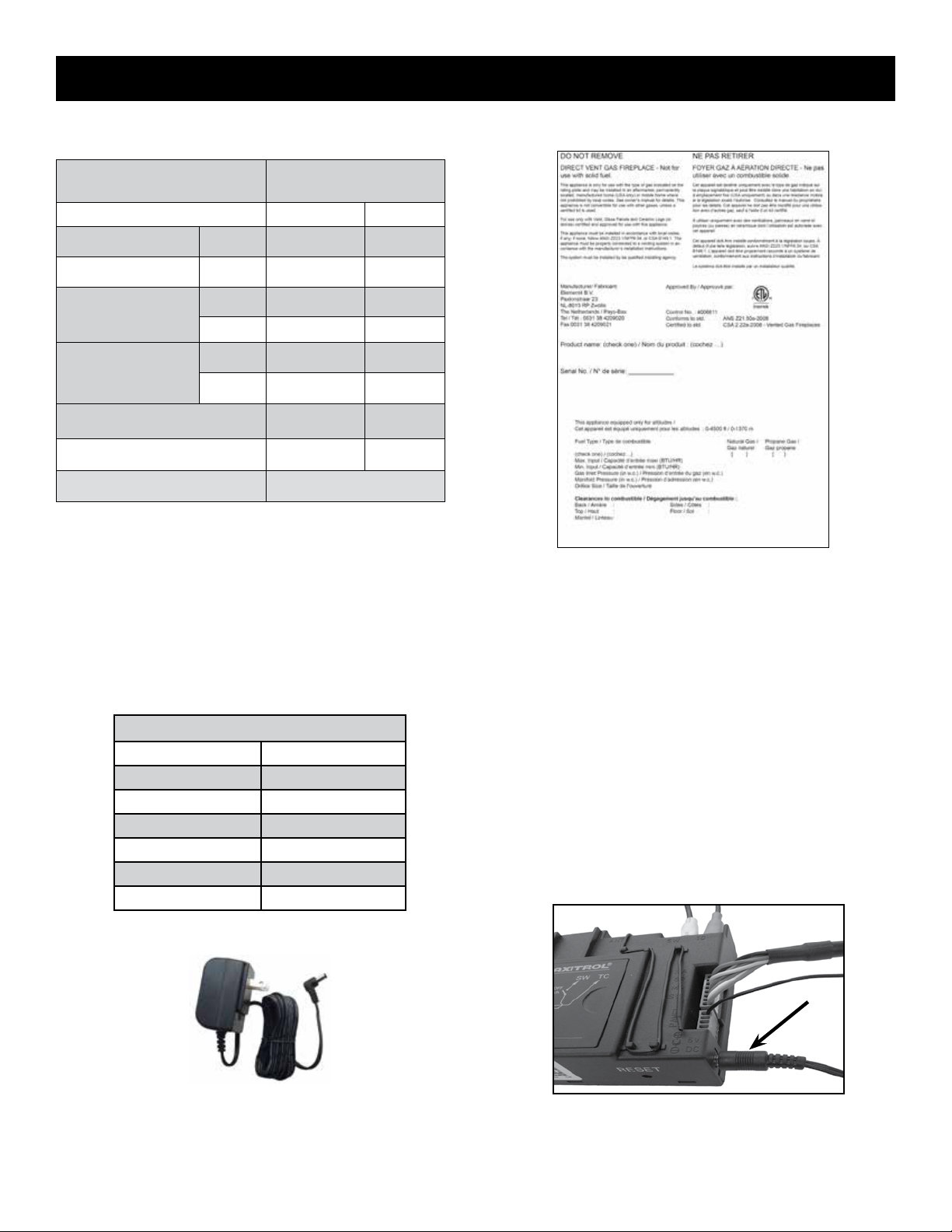
APPLIANCE RATINGS
SPECIFICATIONS and DIMENSIONS
Model
Gas Natural Gas Propane
Input Maximum Btu/hr 44,000 36,000
Input Minimum Btu/hr 17,000 11,000
in. w.c. 7 11
Inlet Pressure
kpa 1.74 2.74
in. w.c. 3.2 10.8
Manifold Pressure
kpa 0.79 2.68
Main Burner Injector Marking 1200 (x2) 280 (x2)
Pilot Injector Marking 31.2 27.1
New Eciency 86%
Sky MKII
Sky T MKII
This product was tested and listed to ANSI
Z21.50a-2008 and CSA2.22a-2008 “Vented
Gas Fireplaces” by Intertek Group. (Figure 3)
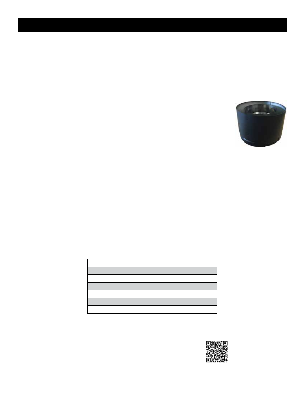
AC ADAPTER SPECIFICATIONS
Input Voltage 120V AC
Input Power 9 W
Output Voltage 6V DC
Output Current 500 mA
Size 3.1”H x 2”W x 1.7”D
Output Cord Length 6 Feet
Agency Approvals UL, CSA
A sample listing label image is shown
above. A metal listing label is attached
to every Element4 replace and contains
important certication information. The
listing label must not be removed from
the replace.
AC Adapter Connection (arrow)
AC Adapter
Element4 Gas Fireplaces EuropeanHome.com
8

SPECIFICATIONS and DIMENSIONS
manufactured by
Element4 B.V.
Sky Cut Sheet
08/2019
EuropeanHome
distributed by
SKY
A DWG le is available for download at www.europeanhome.com for design specic dimensions not listed.
Element4 Gas Fireplaces EuropeanHome.com
9
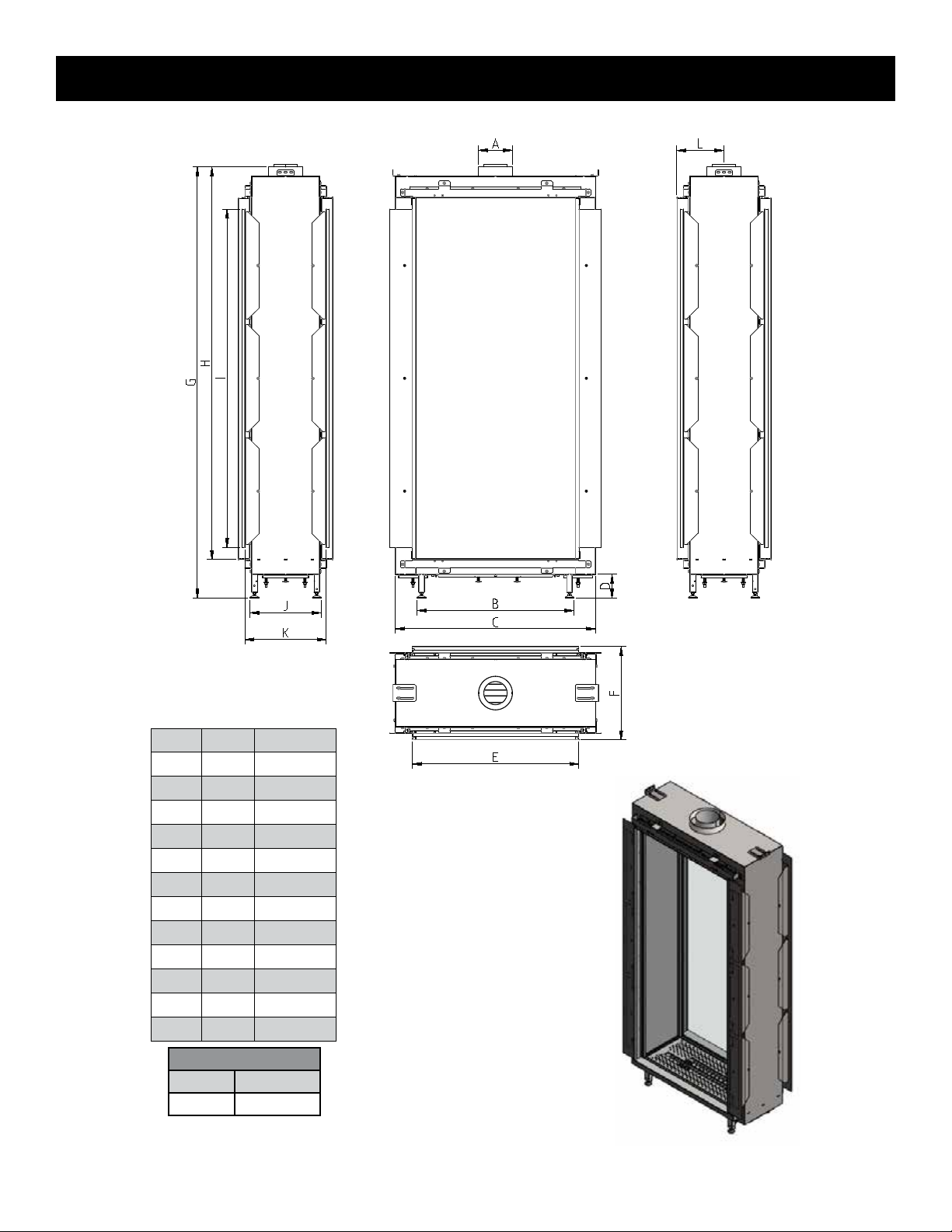
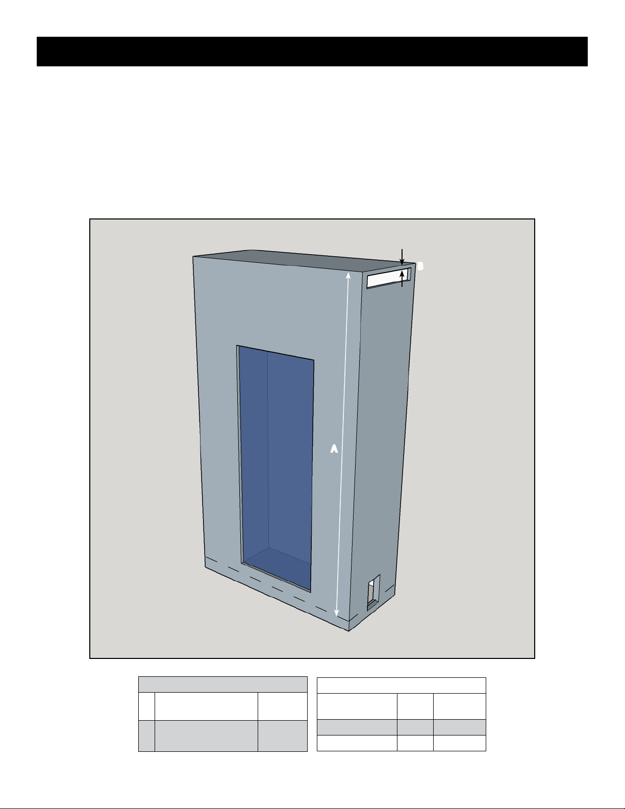
SPECIFICATIONS and DIMENSIONS
Front Elevation
SKY T MKII
Left Elevation
Letter Inches Millimeters
A 8 203
B 27⁄ 688
C 34⁄ 880
D 4⁄ 105
E 28⁄ 732
F 16⁄ 416
G 75¼ 1911
H 68½ 1740
I 59⁄ 1500
J 12⁄ 312
K 15⁄ 385
L 8⁄ 207
Unit Weight
Pounds Kilograms
489 221.8
Right Elevation
Plan View
SKY T MKII
A DWG le is available for download at www.europeanhome.com for design specic dimensions not listed.
Element4 Gas Fireplaces EuropeanHome.com
10
SPECIFICATIONS and DIMENSIONS
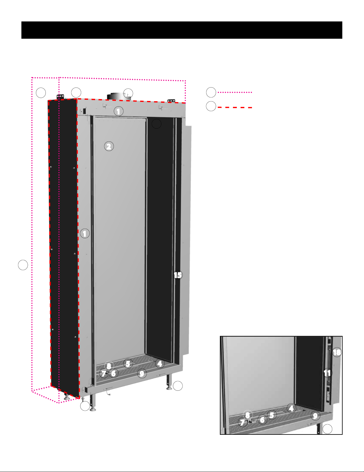
PARTS OF THE FIREPLACE
Parts of the Sky replace are shown following. These parts are also in the Sky T.
16
16
17
12
16
17
1
10
2
1
15
18
8
7
5
6
9
4
11
3
3
8
7
5
6
4
9
3
Element4 Gas Fireplaces EuropeanHome.com
11
SPECIFICATIONS and DIMENSIONS
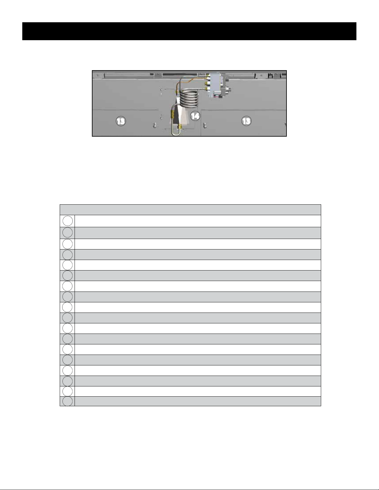
14
13
Fireplace from below.
13
Table of Fireplace Parts
Outer Frame Face- surrounds the glass panel(s) and limits the non-combustible wall board
1
Exterior Glass Panel
2
Support Feet - four adjustable feet allow the replace to be levelled
3
Hearth Panel - supports various Fire Media
4
Primary Burner - produces the front ame
5
Secondary Burner - produces the rear ame; may be controlled separately
6
Pilot Burner - the part of the safety circuit which lights the Main Burner
7
nd
Thermocouple - the part of the safety circuit which monitors the Main Burner
2
8
Finish Trim - hides the Glass Clamps
9
Room Air Inlet (hidden)
10
Glass Clamp - holds the Glass Panel in place (6 ea. - Sky, 12 ea. - Sky T)
11
Vent Collar - accepts the 5” x 8” venting adapter (included)
12
Relief Door - part of the safety system. Do NOT block the operation.
13
Pilot Assembly
14
Side Trim - hides the Glass Clamps (2 ea. - Sky, 4 ea. - Sky T)
15
NO MATERIAL zone
16
Fireplace Limit
17
Flange
18
Element4 Gas Fireplaces EuropeanHome.com
12
CLEARANCES
These are NOT zero-clearance fireplaces. All clearances to
combustible AND non- combustible materials MUST be maintained
as described in this manual.
LOCATING THE FIREPLACE
When selecting a location for the replace:
• Ensure that all minimum clearances to combustible AND noncombustible materials are met.
• Provide adequate clearances for servicing.
• Consider venting dimensions (rise, run and number of
elbows, etc.) when selecting the location for your replace.
• Locate the appliance out of trac and away from furniture
and draperies.
• Keep the location free of electrical, plumbing or other
heating/air conditioning ducting.
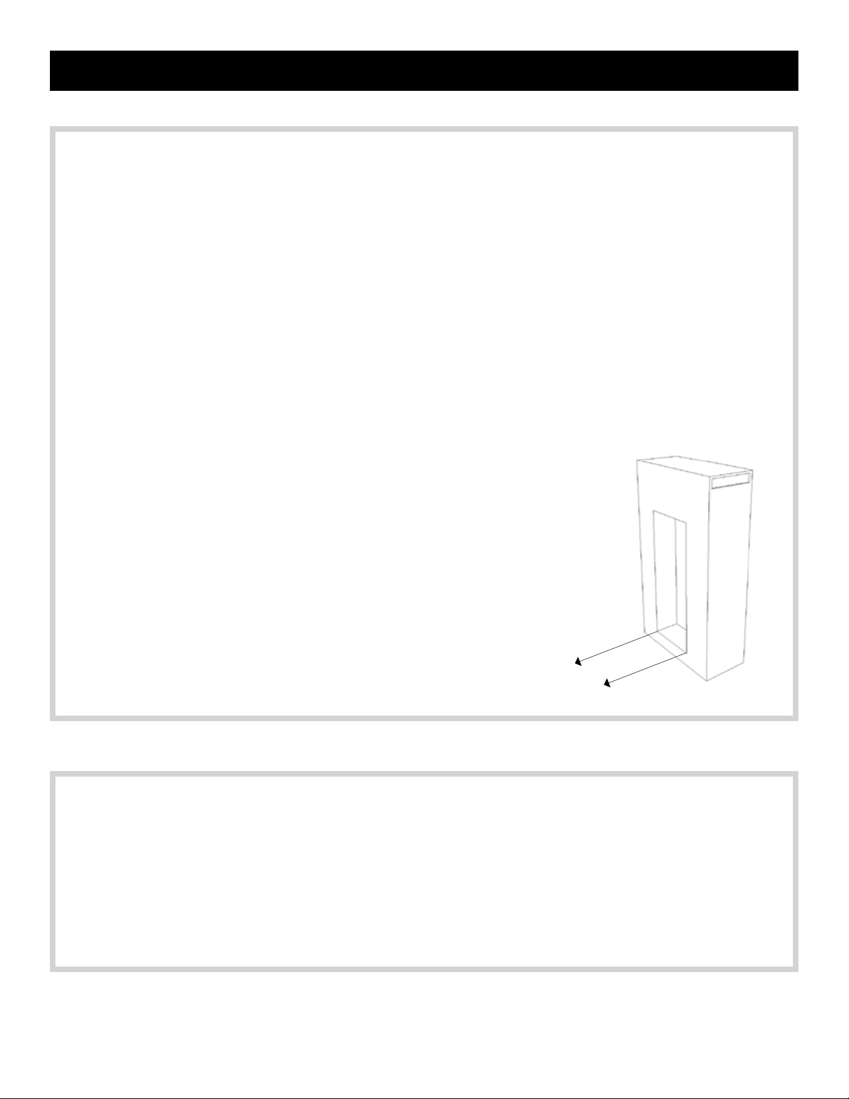
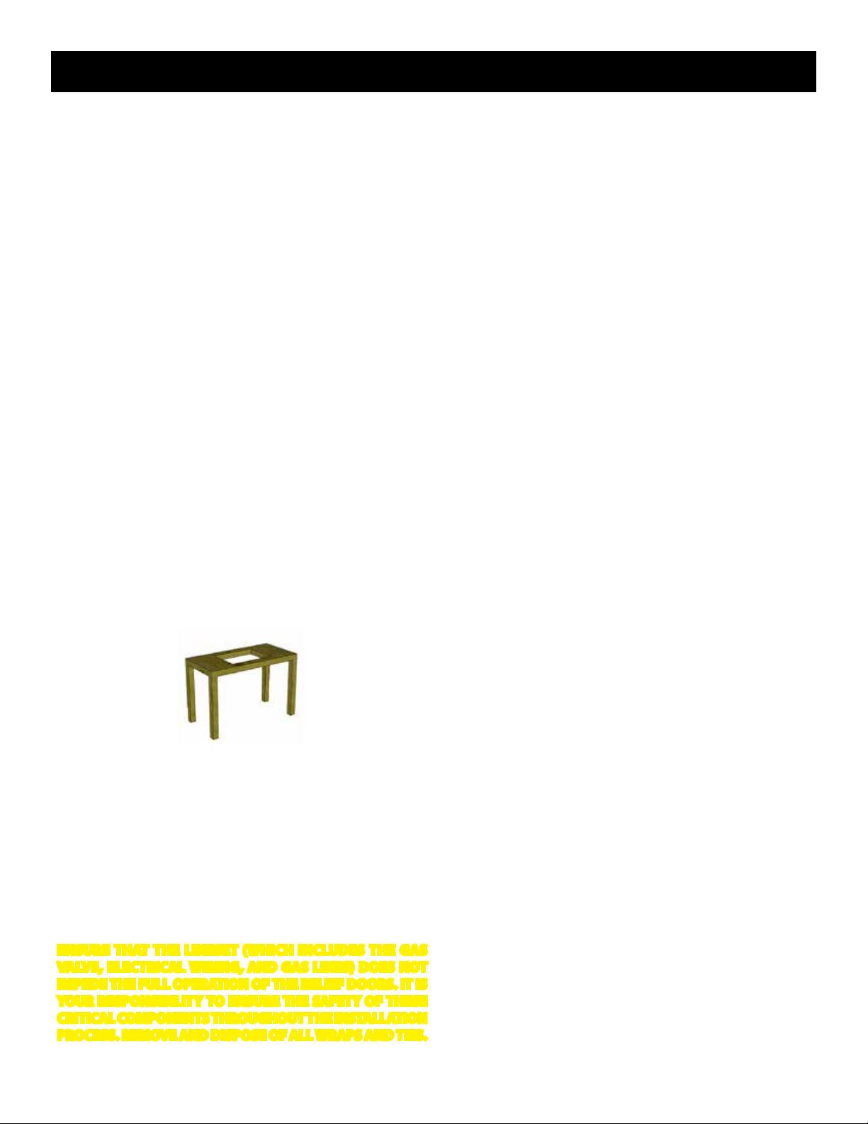
PLACING THE FIREPLACE
The base upon which the appliance rests (Figure __) must be sturdy,
level and built to safely support at least 800 pounds (363 kilograms).
The base may be the oor or a purpose-built raised platform, e.g.
wood, metal. When placed on a platform, an 8” (203 mm) x 6” (152
mm) opening must be cut through the platform top. The lineset can
be routed through this opening. Room air must be allowed to ow
through the Wall Access Door then through this platform opening.
MINIMUM CLEARANCE TO COMBUSTIBLES
• The appliance is approved with a minimum clearance to
combustible materials of 26” (660 mm) to the top, 11” (280
mm)
on all sides and 4” (100 mm) to the bottom. Any spacer
or framing used closer than this dimension must be noncombustible (e.g. metal).
• The minimum distance from the bottom of the appliance to
the room ceiling is 72” (1830 mm).
• When installing the venting, the following clearances to
combustible materials MUST be maintained:
a. 3” (76 mm) above any horizontal venting
b. 1” (25 mm) to venting sides or below any horizontal
venting
• Do not block or restrict the Air Inlet, located between the
stando frame and glass.
The minimum clearances (air spaces) to combustible materials
must be maintained. It is of the greatest importance that the
replace and vent system be installed only in accordance with
these instructions.
Clearance to combustibles summary:
Back: 11” (280 mm)
Front: 11” (280 mm)
Sides: 11” (280 mm)
Top: 26” (660 mm)
Floor: 4” (100 mm)
The Floor dimension (above) is measured from the bottom of
the rebox. When the adjustable feet are in their lowest position
the required clearance to the oor is maintained.
The feet on the appliance are designed to sit on a at platform,
however the appliance must not be installed on any combustible
material other than wood. For example, carpet or linoleum bases
are not permitted.
Do not place anything between the bottom of the rebox and the
bottom of the feet.
ENSURE THAT THE LINESET (WHICH INCLUDES THE GAS
VALVE, ELECTRICAL WIRING, AND GAS LINES) DOES NOT
IMPEDE THE FULL OPERATION OF THE RELIEF DOORS. IT IS
YOUR RESPONSIBILITY TO ENSURE THE SAFETY OF THESE
CRITICAL COMPONENTS THROUGHOUT THE INSTALLATION
PROCESS. REMOVE AND DISPOSE OF ALL WRAPS AND TIES.
Element4 Gas Fireplaces EuropeanHome.com
13
CLEARANCES
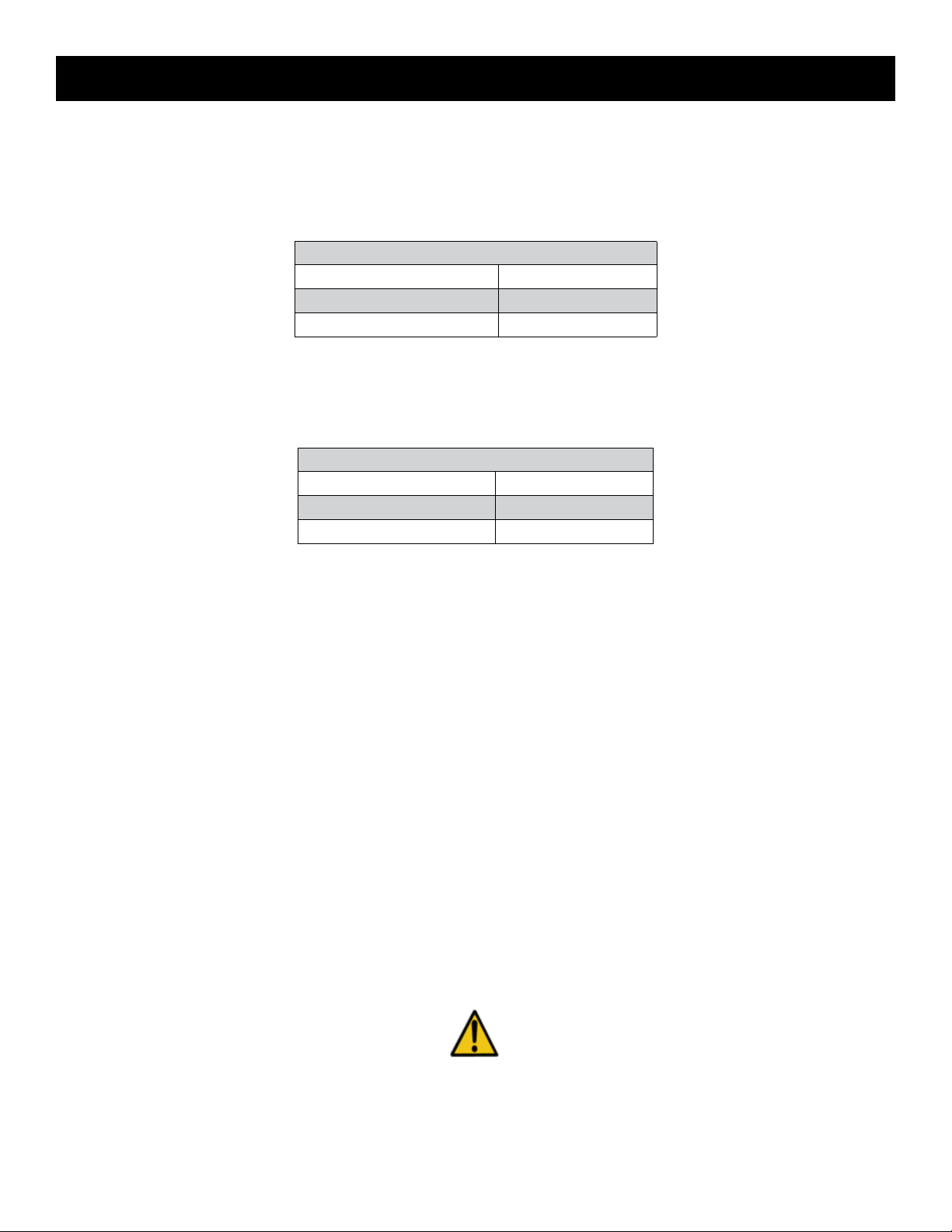
ALL MODELS
CLEARANCES TO COMBUSTIBLE MATERIAL
Clearances to Combustibles
Sides (Non-Glass Sides ONLY) 11”
Top 26”
Bottom 4”
CLEARANCES TO NON-COMBUSTIBLE MATERIAL
Clearances to Non-Combustibles
Sides (Non-Glass Sides ONLY) 2”
Top 2”
Bottom 4”
No material of any kind is allowed between the bottom of the support feet and the bottom of the rebox (except for the
lineset).
No material of any kind is allowed within 2” (50 mm) of the top of the replace.
No material of any kind is allowed within 2” (50 mm) of the metal sides the replace.
Facing material should be installed against the outer frame of the replace, with an ⁄” (3 mm) vertical or horizontal clearance
TO THE FLANGE to allow for heat expansion.
Non-combustible materials may be installed to a zero clearance to the outer faces of the appliance outer frame face. However,
they must not cover (or prevent the removal of) the glass panels or other replace parts.
The appliance must not be installed on any combustible material other than wood.
These clearances are the same for ALL Element 4 Fireplaces, regardless of model.
We recommend that the replace be set into its nal location before building the enclosure.
Please refer to the “Reduced Clearance to Existing Combustible Wall” section for use of combustibles inside of the above clearances.
Element4 Gas Fireplaces EuropeanHome.com
14
CLEARANCES
(2") 50
C
SECTION
A-A
900
COMBUSTIBLE MATERIALS
NOT PERMITTED IN FRONT
OF GLASS
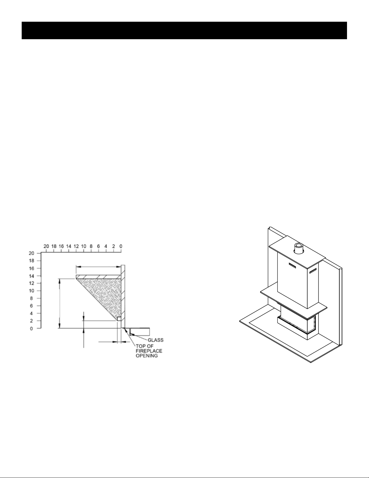
MANTELS
The graph below shows a range of allowable depths and heights for a combustible mantel installation.
As shown, the minimum allowable mantel height above the replace opening is 2”/50 mm with a 1”/25 mm deep mantel.
The maximum mantel depth is 12”/300 mm at a minimum height above the replace opening of 13”/330 mm.
All of the mantel height/depth combinations fall in between these extremes in accordance with the chart below.
Mantels made of non-combustible material are allowed inside these dimensions but they will be subjected to elevated
temperatures and may become too hot to touch.
A typical completed installation with mantel is shown in the diagram below, on the right.
INCHES
13”/330 mm
Mantel Height
Mantel Depth
12”/300 mm
1”/25 mm
2”/50 mm
Element4 Gas Fireplaces EuropeanHome.com
15
CLEARANCES
TYPICAL CLEARANCE DIAGRAMS
The total area of the air openings must be maintained. The location of the openings must allow for the free movement of air and
must not allow excessive warm air to build up within the chase.
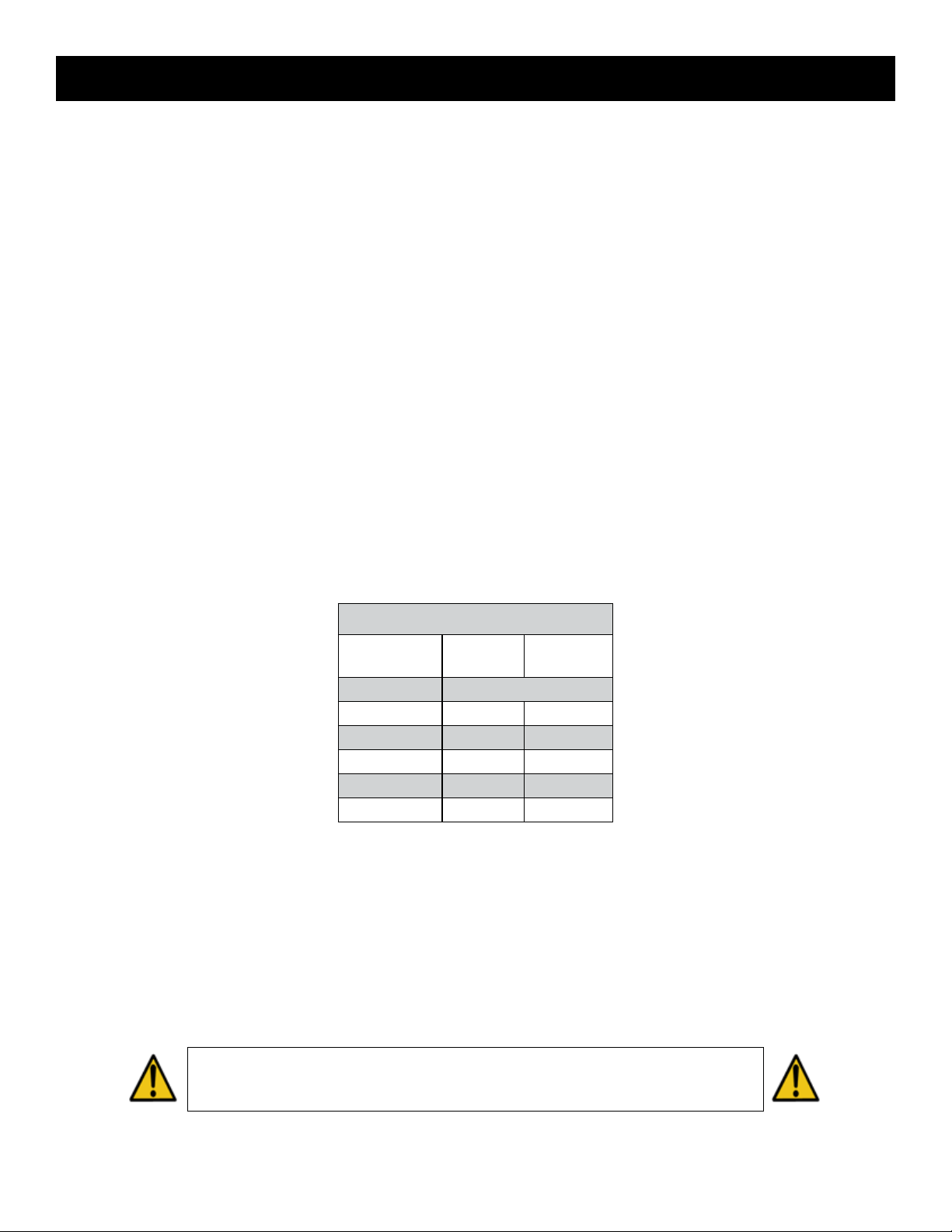
The top of the Warm Air Outlet must be no more than 1” (25 mm) down from the chase ceiling.
The minimum distance from the bottom of the appliance to the room ceiling is 72” (1830 mm).
Warm Air
Outlet
B
Minimum Distances
Room ceiling to
A
appliance bottom
Room ceiling to top of
B
Warm Air Outlet
72”
1830 mm
1”
25 mm
A
Warm Air Outlet Area by Model
Model
Square
Inches
Square
Centimeters
Sky 50 322
Sky T 50 322
Element4 Gas Fireplaces EuropeanHome.com
16
GAS and ELECTRIC
INSTALLING THE GAS LINE
In accordance with the latest edition of the National Fuel Gas Code, NFPA 54 (USA) or CAN/CSA-B149.1 (Canada,) correctly size and
route the gas supply line from the supply regulator to the area where the appliance is to be installed.
Never use galvanized or plastic pipe unless it is rated for use with gas. Gas supply pipes must be designed, routed, constructed and
made of materials that are in strict accordance with local codes and regulations. A qualied plumber or gas tter should be hired to
correctly size and route the gas supply line to the appliance in accordance with all applicable codes and regulations.
Installing a gas supply line from the fuel supply to the appliance involves numerous considerations of materials, protection, sizing,
locations, controls, pressure, sediment trap, and other criteria. The sizing and/or installing of gas piping should only be performed
by a qualied plumber or gastter.
The gas control inlet accepts a ⁄” NPT tting.
The gas supply piping should have a separate gas shuto valve and a capped, 1/8” pipe tapping upstream of the valve for the purpose
of reading pressure. A service shuto valve must be placed within six feet of the replace gas control valve.
The gas supply pressure at the gas control valve must not exceed the Maximum Supply Pressure as shown in the Specications
and Dimensions section of this manual.
The gas supply line must be properly connected and bled by a certied gastter or plumber.
The appliance and its main gas valve must be disconnected from the gas supply piping system during any pressure testing of that
system at test pressures in excess of ½ psi (3.5 kPa). The appliance must be isolated from the gas supply piping system by closing
its equipment shuto valve during any pressure testing of the gas supply piping system at test pressures equal to or less than ½ psi
(3.5 kPa).
Schedule 40 Black Iron Pipe
Length (feet) Inside Diameter (Inches)
0 - 10 ½ ⁄
10 - 40 ½ ½
40 - 100 ½ ½
100 - 150 ¾ ½
150 - 200 ¾ ½
Natural
Gas
Propane
Gas
ELECTRICAL REQUIREMENTS
The Element 4 replaces use a receiver and remote control for their burner operation. The remote control comes with two AAA
batteries and the receiver is powered by a 120V AC adapter, included. The replace MUST be powered by the AC adapter for
improved reliability and customer satisfaction.
The installer must provide an approved 120V AC receptacle to be placed within the six foot cord limit of the AC adapter.
The receiver MUST be powered by the AC adapter. Four (4) AA batteries may be used only for on-demand electrical requirement
during a power outage. Remove batteries after use to avoid battery corrosion. Battery corrosion will damage the receiver.
Electrical work must be performed by a qualied, licensed electrician.
WARNING
All wiring shall be in compliance with all local, city, and state codes.
Element4 Gas Fireplaces EuropeanHome.com
17
VENTING
CONFIGURATION
CONFIGURING THE VENTING
The replaces in this manual are direct vent replaces that use a co-axial or “pipe within a pipe” venting system. The outer “pipe” or vent
conducts fresh, outside air into the replace and the inner vent carries the exhaust outside. This system, which can run either horizontally
through a side wall or vertically through the roof, produces an ecient system because conditioned building air is not used for combustion.
• Only the 5” x 8” direct vent components from the companies listed below (Figure __) are approved for use with
these replaces. Any of the 5” x 8” direct vent components suitable for the local condition are permitted. Please visit
www.europeanhome.com/qr-support or via the QR code below for installation instructions.
• This replace is shipped with a North American venting adapter (Figure __). It MUST attach to the
vent collar of the replace.
• All venting measurements are taken from the top center of the vent collar on the top of the replace
and all congurations must fall within the acceptable range of the venting charts.
• A minimum clearance of 3” (75 mm) must be maintained between combustible materials and the top
of any horizontal vent pipe surface; a minimum clearance of 1” (25 mm) must be maintained between
combustible materials and any other vent pipe surface.
• The horizontal parts of the venting must be pitched up away from the replace. For every 12” (305 mm) of horizontal run, the
venting must rise ¼” (6.5 mm) toward the termination. The venting must never run downward unless with the use of a power
vent.
North American Vent Adapter
• Whenever venting passes through a wall, an approved heat shield or ‘wall thimble’ must be installed.
• A power vent system is available for venting that falls outside of the venting graphs. Refer to the appropriate power vent
manual for any venting conguration which is outside of the vent graphs shown here.
• Your venting needs to be inspected annually, including any connected components, to ensure that the system is working as
designed.
• In colder climate environments, the replace can be lowered to STANDY BY MODE (Pilot Flame only). This will help maintain a
steady draft within the venting over a period of up to ve days. See the “Operating the Fireplace” section.
APPROVED COMPONENTS and MANUFACTURERS
DirectVent Pro (M&G DuraVent, Inc.)
EXCELDirect (ICC - Industrial Chimney Company)
Pro-Form (BDM - Bernard Dalsin Manufacturing)
Direct-Temp (Selkirk Corporation)
AmeriVent Direct Vent (Hart & Cooley Inc.)
Ventis Direct Vent (Olympia Chimney Supply, Inc.)
Please visit www.europeanhome.com/technical-support/
for the power venting installation manuals
Element4 Gas Fireplaces EuropeanHome.com
18
VENTING
CONFIGURATION
R
R
N
N
S
T
N
S
N
N
S
T
S
Q
T
R
N
S
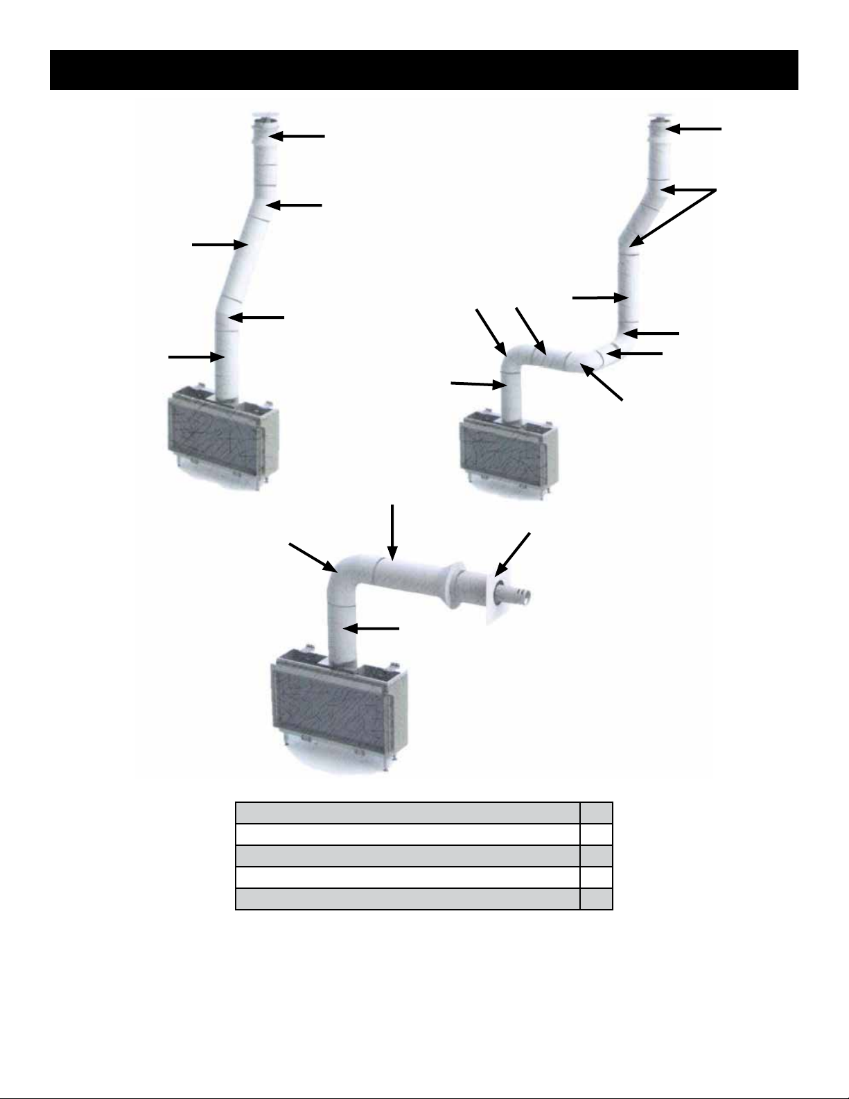
Vertical or Horizontal Vent Termination R
45 or 90 degree bends Vertical to Horizontal or vice versa N
45 and 90 degree bends Horizontal to Horizontal Q
Horizontal Pipe Section T
Vertical Pipe Section S
CALCULATING THE TOTAL VERTICAL SECTION (TVS)
Calculate the Total Vertical Section by adding up all vertical upward sections in your specic vent design.
CALCULATING THE TOTAL HORIZONTAL SECTION (THS)
Calculate the Total Horizontal Section by adding up all horizontal sections in your specic vent design.
Element4 Gas Fireplaces EuropeanHome.com
19
 Loading...