

European Home DV 42 ST Installation, Operation And Maintenance Manual
C US
Installation,
Operation and
Maintenance
Manual
DV 42 ST
See-through
Gas
Fireplace
Check local codes and read all
instructions prior to installation.
Warning:
Improper installation, adjustment, alteration, service or maintenance can cause injury or
property damage. Refer to this manual. For assistance or additional information consult a
qualied installer, service agency or the gas supplier.
Safety Notice:
Glass doors on gas replaces are extremely hot while the replace is on and remain hot even after the
replace has been turned o. Safety screens are available and can reduce the risks of severe burns.
For Your Safety:
Do not store or use gasoline or other ammable vapors and liquids in the vicinity of this or
any other appliance.
®
Warning:
What to do if you smell gas
• Do not try to light any appliance.
• Do not touch any electrical switch; do
not use any phone in your building.
• Immediately call your gas supplier
from a neighbor's phone. Follow the
gas supplier's instructions.
• If you cannot reach your gas supplier,
call the re department.
• Installer: Leave this manual with
the appliance.
• Consumer: Leave this manual for
future reference.
DV 42 ST See-through Gas Fireplace
Warning:
Read this manual before installing, operating or troubleshooting this appliance.
Please retain this owner's manual for future reference.
Congratulations
Congratulations on selecting a European Home gas replace, an elegant
and well designed gas replace built with you in mind. The gas replace
you have selected is designed to provide the utmost in safety and reliability.
As the owner of this new replace, you'll want to read and carefully
follow all the instructions contained in this Installation, Operations and
Maintenance manual. Pay special attention to all cautions, warnings, and
Important warnings.
This owner's manual should be retained for future reference. We suggest
that you keep it with all your other important documents and product
manuals.
The information contained in this owner's manual, unless noted otherwise, applies to all models, and gas control systems.
Your new gas replace will give you years of durable, reliable use. Welcome to the European Home family of gas replace products.
Safety Alert Key:
• DANGER!
Indicates a hazardous situation which, if not avoided will result in death or serious injury.
• WARNING! Indicates a hazardous situation which, if not avoided could result in death or serious injury.
• CAUTION! Indicates a hazardous situation which, if not avoided, could result in minor or moderate injury.
• NOTICE: Used to address practices not related to personal injury.
• Important: Used to address practices not related to personal injur y.
Table Of Contents
Congratulations
Safety Alert Key
Introduction ............................................................................................... 3
Installation
Installing and Framing the Fireplace .........................................3 - 4
Installing the Gas Line ....................................................................5
Vent Installation ............................................................................. 5
Installation Requirements .............................................................. 5
Installing the Remote Switch.......................................................... 5
Vent Terminations........................................................................... 6
Installing the Nailing ange ...........................................................6
Top Vent Runs ............................................................................ 7 - 8
Side Vent Runs .........................................................................8 - 11
Power Vent Runs ........................................................................... 11
Finishing around the replace
Fireplace Facing ............................................................................ 11
Mantels and Surrounds .................................................................12
Wiring ............................................................................... 12 - 13
Wiring for the Optional Fan Kit ..................................................... 13
Removing and Installing the Door ......................................... 13 - 14
Operation .......................................................................................... 15 - 18
Maintenance .................................................................................... 18 - 19
General ......................................................................................... 18
Troubleshooting .................................................................... 18 - 19
Spare Parts ...................................................................................19
Warranty .................................................................................................. 20
Appendix
A. Termination Locations .............................................................. 21
B State of Massachusetts/Amendment ........................................ 22
Page 2
rev.110308
Introduction
DV 42 ST See-through Gas Fireplace
Thank you for choosing a European Home Gas Fireplace.
About this Fireplace:
The DV 42 ST (See-thru) is a replace with a linear-style burner. This replace can
be converted to both a Top Vent or Rear Vent application, and is available in the
models below.
MODEL
DV 42 ST X X 34,000 X
DV 42 ST E X X 34,000 X
This manual covers all models and unless otherwise specied, the designation DV 42
ST refers to all variations of the model above. Sections which are specic to a particular
variation are marked with a symbol, plus the appropriate model number.
Warranty and Installation Information:
The European Home warranty will be voided by, and European Home disclaims any
responsibility for, the following actions:
Modication of the replace and/or components including Direct-Vent assembly or glass doors.
Use of any component part not manufactured or approved by European Home in combination
with this European Home replace system.
Installation other than as instructed in this manual.
Consult your local Gas Inspection Branch on installation requirements for factorybuilt gas replaces. Installation and repairs should be done by a qualied contractor.
Installations in Canada must conform to the current CAN/CGA B-149.1 and .2
Gas Installation Code and local regulations. If the optional air-circulating fan kit is
installed, it must be electrically grounded in accordance with CSA C22.1 Canadian
Electrical Code Part 1 and/or Local Codes.
Installations in the USA must conform to local codes, or in the absence of local
codes to the National Fuel Gas Code, ANSI Z223.1-1988. If the optional air-circulating
fan is installed, it must be grounded in accordance with local codes or, in the absence
of local codes, with the National Electrical Code, ANSI/NFPA 70-1987. Within the
State of Massachusetts this replace must comply with NFPA-54 Chapter 10.
Natural Gas
Liquid Propane
Gas Rating
(BTU/hr)
Standard Pilot
Ignition
Electronic Ignition
CAUTION!
Due to its high operating temperatures, the appliance should be
located out of trac and away from furniture and draperies.
Children and adults should be alerted to the hazards of the
high surface temperature, which could cause burns or clothing
ignition.
Young children should be carefully supervised when they are in
the same room as the appliance.
Clothing or other ammable materials should not be placed on
or near the appliance.
WARNING!
When this appliance is installed directly on carpeting, tile or any combustible
material other than wood ooring, it must be installed on a metal or wood
panel extending the full width and depth of the appliance.
Installing The Fireplace Shell
The DV 42 ST replace may be installed in any location that maintains proper clearances to air conditioning ducts, electrical wiring and plumbing. Safety, as well as
eciency of operation, must be considered when selecting the replace location. Try
to select a location that does not interfere with room trac, has adequate ventilation,
and oers an accessible pathway for direct vent installation. Refer to page 4 - Vent
Installation for more information.
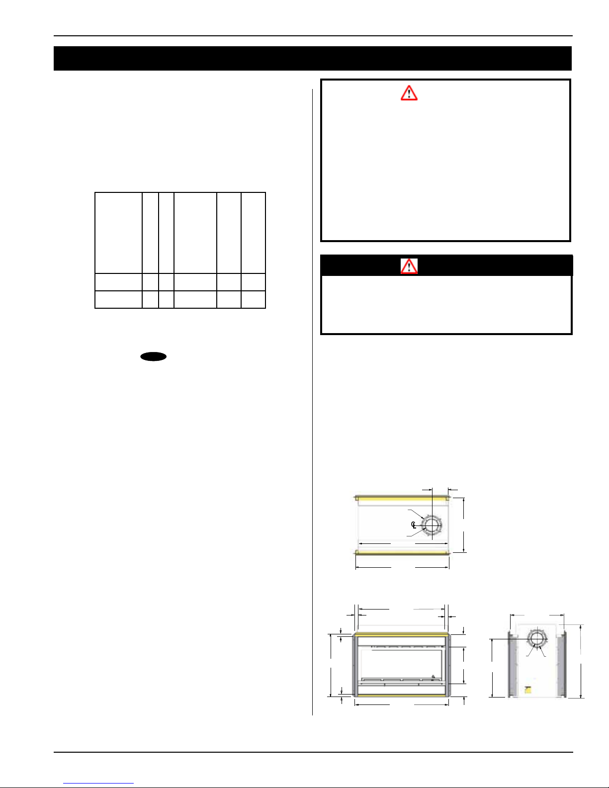
The replace dimensions are shown below:
7"
8"
24"
5"
40¾"
42"
Top View
1¼"
1¼"
30½"
39½"
1¼"
6¼"
19"
27¾"
24"
5"
8"
34½"
rev.110308
1"
Figure 1. Fireplace dimensions.
42"
Front View
5¼"
Side View
Page 3

DV 42 ST See-through Gas Fireplace
-
Installation
Frame in the enclosure for the unit with framing materials. The framed opening
for the assembled replace is 45" wide, x 40" high x 23 ¾" deep, see Figure 2
NOTE: When constructing the framed opening, please ensure there is access
to install the gas line when the unit is installed. See Figure 22.
45"
40"
36"
Notes:
Install supplied metal headers (Part No. H42ST060)
above replace after unit is in place.
Use supplied hardware to attach to framing. Both
Walls Typical. May not be exactly as shown.
Both walls Typical.May
not be exactly as shown.
Note:
When facing with the
Overlay Method the depth
is increased by 1". See
Planning Guide for more
information.
40”
23¾"
or
24¾"
Framing Kit, 4-pcs. (Part No. L42FS01B) Install
with supplied hardware. Both walls and sides
Typical. See Figure 2a below.
Figure 2. Framing dimensions.
Supplied shield
.
N.G. & L.P
PEL Short
90 elbow
41”Min N.G.
54”Min L.P.
Combustible Shelf
2” Min.
Figure 4. Combustible Framing for shelves over the replace, top vent.
Top vent
N.G. & L.P
Min. 1”
Combustible
Header
Supplied
Header
7”
7”
21”
Min.
Alcove over
Fireplace Non
Combustible
Materials Only
Non
Combustible
Header
10”
Combustible materials may be used,
(left & right), surround & bottom.
Above fireplace see Fig. 24 & 25.
Framing Kit, (Part No. L42FS01B,
4-pcs. Fasten to Combustible
framing with supplied hardware.
Backframe Min. 42”
both sides Typical
Figure 2a. Framing dimensions, back-framing
L.P. & N.G
1” Min
1” Min
90°
Supplied shield
Combustible
shelf
12” Min.
40”
36”
door
opening
Floor
30 1/2”
Figure 5. Non Combustible Framing with alcove above replace, right side. Combus-
tible framing above replace, left side, see gure 2. (Top Vent).
Clearances
When installing a shelf over the top of the replaces, the following must be observed:
For Rear Vent applications, the minimum clearance is 2" from the rear of the replace
to a wall, or any combustible materials, and 12" clearance from the top of the replace
to the underside of any combustible shelf materials.
For Top Vent applications, the minimum clearance is 2" from the rear of the replace
to a wall, or any combustible materials, and 21" to the underside of any combustible
shelf materials.
(Minimum 2" clearance must still be maintained around the vent pipes.)
Figure 3. Combustible Framing for shelves over the replace, Rear vent.
Page 4
MODEL
Top - Rear Vent *
Top - Top Vent
Back
Sides
Floor
DV 42 ST 12" 21" 2" 1" 0" 6"
Mantel
rev.110308
Installation
DV 42 ST See-through Gas Fireplace
Gas Installation
FUEL CONVERSION
Verify that your replace is compatible with your available gas type.
If gas type is not compatible, contact your local European Home representative
to purchase a conversion kit.
Conversion kits must be installed by a qualied service technician.
GAS PRESSURE
Optimum appliance performance requires proper input pressures.
Gas line sizing requirements will be determined in ANSI Z221.3 National
Fuel Gas Code in the USA and CAN/CGA B149 in Canada.
Pressure requirements are:
Gas Pressure Natural Gas Propane
Minimum inlet pressure 5.5in. w.c. 11in. w.c.
Manifold pressure 3.5in. w.c. 10in. w.c.
The manifold outlet pressure is set from the factory to the appropriate
pressure but should be veried.
To check pressures, control valves have a provision to remove a ⁄” NPT plug
to be tted with a hose barb.
European Home requires a service shut o valve be located in an accessible
location to isolate the gas supply.
Only install gas shut-o valves approved for use by the state, province, or
other governing body in which the replace is being installed.
GAS CONNECTION
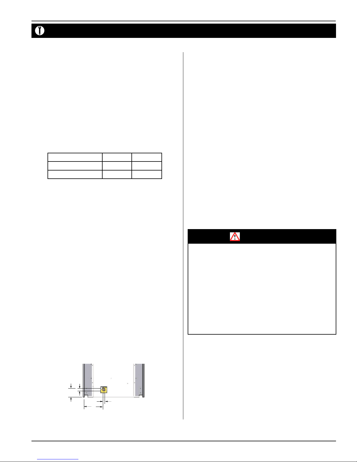
See Figure 22 below for location of gas line access.
Flexible gas connectors must not exceed 3 feet in length, unless allowable
within local regulations.
Connect incoming gas line to the 1/2"or 3/8" gas inlet port.
Purge all air out of gas line.
Check appliance connection, valve and valve train under normal operating
pressure with a commercially available leak check solution.
DO NOT USE A FLAME OF ANY KIND TO TEST FOR LEAKS.
Vent Installation
This section covers the installation of direct venting and terminations.
Installation Requirements
Q DV 42 ST replace is certied for use with European Home Standard Series (5" / 8")
venting components.
Q Minimum clearance to combustible construction around the vent pipe is 1" on
all sides, except on horizontal venting where the top of the pipe must have a clearance
of at least 2".
Q Use only certied European Home vent components. (Use of other parts will void the European
Home warranty, and may impede the operation of the replace.)
Q All joints must be secured with a minimum of two screws per joint
Q Vent terminations must not be recessed in walls or siding
Q Horizontal runs must be supported by a minimum of two supports per horizontal run. A
minimum of one screw on each side of support is also required
Q Flex vent sections may be stretched up to 50% of their total length (e.g. a 24" section
may be stretched to 36")
Q Flex vent sections over 6 feet must fall within the limits set by the venting graph and must
have a minimum vertical rise of 3 inches per foot of ex.
Q Solid vent sections may be cut less than half way from the female end
Q Venting components can be used in any combination of solid/rigid pipe or ex pipe and
in any orientation (Male connectors can face in any direction)
Cautions:
Q Vent terminations can be very hot. If the termination is less than
7 feet above a public walkway, it should be tted with a certied
European Home Heat Guard. (Part no. PTKOG).
Q Do not obstruct, or attempt to conceal, the vent termination.
These actions will aect the operation of the replace, and may
be hazardous.
Q In heavy snow areas, take extra care to prevent snow buildup from
obstructing the vent termination.
Q Use European Home VSS Vinyl Heat Shield when using on applications
with vinyl siding to guard against possible damage.
1 3/4”
2 3/8”
1 3/4”
7”
Figure 22. Gas line access.
rev.110308
Installing The Remote Switch
The DV 42 ST gas valve, located behind the lower trim, may be connected to a wall
switch. The valve generates its own power on a millivolt circuit. Use only low
voltage wire, and DO NOT connect any external power to it.
Note: The switch location must not exceed 30' from the replace.
Page 5

DV 42 ST See-through Gas Fireplace
12
12
11
11
1212
12
Installation
Installing Terminations with Built-In Frames
PTO-4 (5"/8")
Figure 5a. Installing a PTO termination.
1. Frame the termination opening to 11" x 11".
2. Fasten the termination to the studs using a minimum of 4 screws.
Installing Terminations with MSR Frames
MSR
Installing Heat Guards over Terminations
PTKOG (5"/8")
Figure 5d. Installing a PTO termination heat guard.
1. Ensure that the two long mounting brackets are facing the bottom of the
termination. (See inset). This will provide more heat protection at the top of
the termination, where temperatures are highest.
2. Attach to the faceplate of the termination using four sheet metal screws.
CAUTION:
Do not obstruct, or attempt to conceal, the vent termination. These actions
will aect the operation of the replace, and may be hazardous.
PTO-4 (5"/8")
Figure 5b. Installing a PTO termination with the MSR frame.
1. Frame the termination opening to 12" x 12".
2. Fasten the termination to the studs using a minimum of 4 screws.
Installing Terminations with MOSR Frames
MOSR
PTO-4 (5"/8")
Figure 5c. Installing a PTO termination with the MOSR frame.
1. Frame the termination opening to 12" x 12".
2. Fasten the MOSR frame to the interior side of the studs using a minimum of 4
screws.
3. Insert the termination into the MOSR frame as shown here, and attach by
screwing through the four pilot holes in the termination.
Page 6
In heavy snow areas, take extra care to prevent snow buildup from obstructing
the vent termination.
Installing the Nailing
Flange Extension
Once the replace is placed into the rough framed opening and the supplied steel
lintel is in place (Part No. L42087) (see Figure 2), the supplied nailing ange
extension must be placed along the top edge of the replace and securely fastened
in place to the metal lintel and combustible wood framing. Note: The nailing ange
extension can be substituted with a piece of NON-COMBUSTIBLE material of the
same size and thermal characteristics, i.e.: cement board or equivalent.
Figure 6. Installing the Nailing Flange Extension.
rev.110308
Installation
DV 42 ST See-through Gas Fireplace
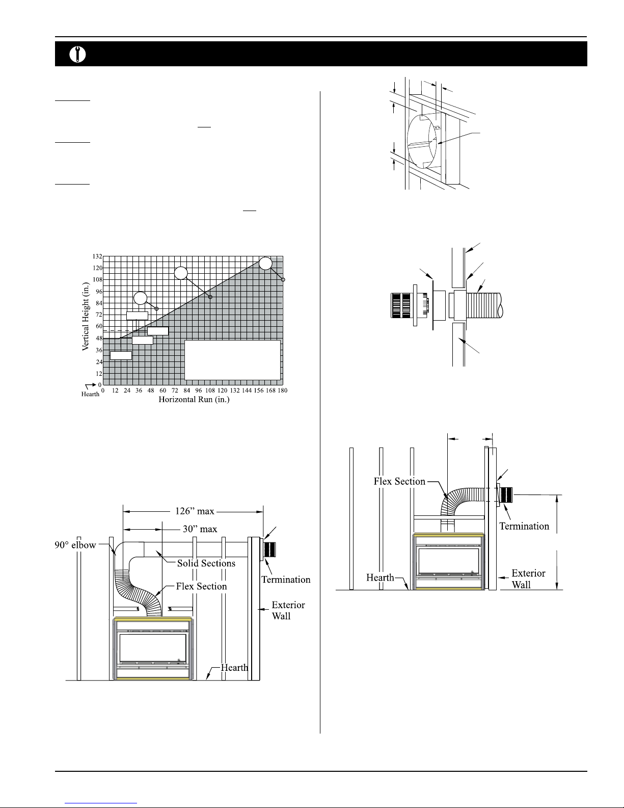
Top Vent Venting Runs
Example A: (Unacceptable Installation N.G. and L.P.)
If the vertical dimension from the hear th is 108" and the horizontal run to the wall ange
of the vent termination is 180", this would NOT be an acceptable installation.
Example B: (Acceptable Installation N.G. and L.P.)
If the ver tical dimension from the hear th is 54" and the horizontal run to the wall ange
of the vent termination is 78", this would be an acceptable installation.
Example C: (Unacceptable Installation N.G. and L.P.)
If the vertical dimension from the oor of the replace is 90" and the horizontal run to
the wall ange of the vent termination is 108", this would NOT be an acceptable
installation.
A
C
B
34”
L.P.
N.G.
19”
Figure 7b. DV 42 ST Top Vent Venting Graph
41”
54”
Power Vent models, LDVPV47
EDVRSPV58, and EDVWSPV58
to be used within the shaded area of
graph. (See Index of this guide for
applicable Product page).
1 MIN
1 MIN. Both
sides Typical
RHS8 Heat
Shield
1 MIN
Figure 8a. RHS8 Installation. (Install by sliding over vent pipe where it passes through
the combustible construction.
Drywall
RHS101 Heat Shield,
Outer Section.
RHS101 Heat Shield,
Inner Section.
Vent from fireplace
Termination
Framing
Figure 8b. RHS101 Installation. (Install by sliding over vent pipe where it passes through
the combustible construction.
NOTES: All dimension lengths for vertical or horizontal runs are measured
from center of the vent pipe.
Venting runs must fall within the limits set by the venting graph
(see Figure 9a).
RHS8
Figure 8. Retracted Installation using a combination of solid and ex venting. Use
the vent graph to determine your allowable run, then select appropriate
components.
19
max
RHS101
41 min N.G.
54 min L.P.
Figure 9. Horizontal ex installation with minimum vertical rise.
B. Vertical (Through-The-Roof) 5/8 Installations
Vertical rise >12' can be reduced (on applicable models).
Vertical Terminations must be installed:
• minimum 2' (two feet) above the highest point where
vent passes through the roof.
• minimum 6' (six feet) from a mechanical air inlet
• minimum 18" (1 1/2 feet) from a parapet wall.
rev.110308
Maximum vent height is:
• 32 feet above replace.
Page 7

DV 42 ST See-through Gas Fireplace
Installation
Note: Flame characteristics will change if the maximum vent height is used.
A maximum of two osets (each oset has two 90° bends) may be made and
shall not exceed total length of 25% of the vertical vent height, when measured
center to center of piping.
Example: Typical vent installation.
20' vertical vent
2 - 2' osets required
25% of 20' = 5' max. oset allowed
This venting conguration meets requirements.
5" / 8" Venting
A - Termination PVTK-1
B - Flex Sections PFL-1 (12" Section)
C - Rigid Sections PEXT-1 (12" m/f Section)
D - Support Ring
& Plate
E - Firestop PS-8
F - Roof Flashing PRF-7 (1/12 - 7/12 pt.)
G - Adaptor / Vent
Reducer
PFL-2 (24" Section)
PFL-3 (36" Section)
PFL-4 (48" Section)
PEXT-2 (24" m/f Section)
PEXT-3 (36" m/f Section)
PEXT-4 (48" m/f Section)
PSPXT-8
PRF-7 (7/12 - 12/12 pt.)
PVA5487 (5"/8" to 4"/7")
Figure 11. Vertical venting with 1 oset (1 oset= two 90° bends).
PEXT
* For venting minimum 1" clearance to all vertical combustibles,
minimum 2" to all horizontal combustibles.
Figure 10. Straight, vertical venting showing required PXT-10 adaptor (supplied
with the PVTK-1 termination).
Page 8
* For venting with four 90° a restrictor may need to be used. (PEXT 5/8 Vent).
Figure 12. Vertical venting with 2 osets (1 oset= two 90° bends).
rev.110308
 Loading...