

Europa components TPN Series, TPNEB, TPNA16W, TPNMM Important Information Manual
TPN 3 Phase
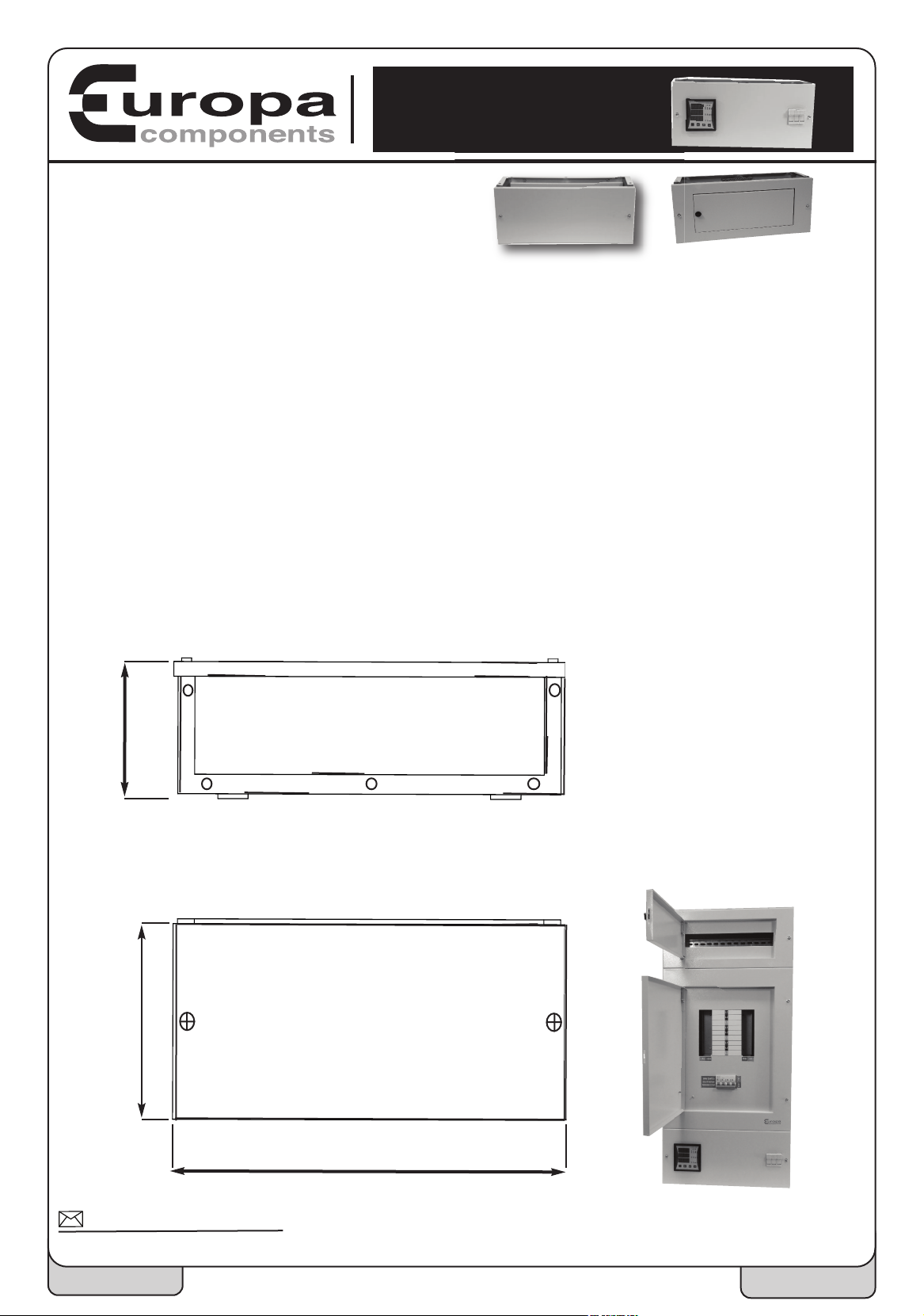
200
465
135
Extension Boxes
Important Information
his unit must be installed by a qualified competent person in compliance with current requirements for
T
Electrical Installations (IEE Wiring regulations Seventeenth Edition: BS7671).
! Ensure that all power supplying this equipment is switched OFF before working on or inside the unit.
! Confirm the power is off with an appropriately rated volt-sensing device.
! Make sure all devices, covers and doors are replaced and secured before switching the power supply back on to the unit.
! Remove the gland plates prior to slotting or cutting for cable entries to avoid ingress of swarf & other debris.
! The user guide must be available for future reference after installation and testing.
Failure to follow these instructions could result in serious injury or death
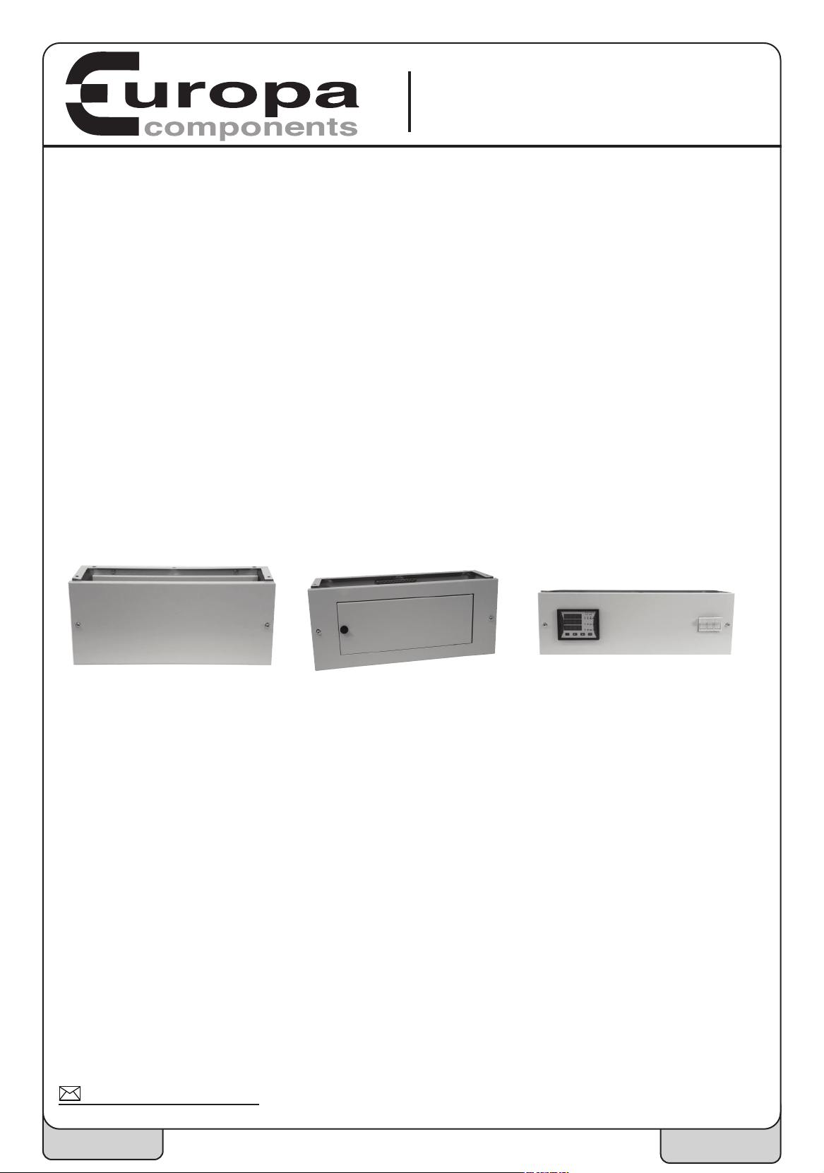
Models Available:
TPNEB Empty Expansion Box
TPNA16W 16 Way Type A Modular Service Box
TPNMM Multi-Function Meter Box
All models can be mounted to the top or the bottom of a TPN distribution board although as standard the TPNMM and the
TPNEB come ready to mount to the underside and the TPNA16W to the top of the TPN distribution board.
You Will Need:
n Pozidrive PZ2
135
ions
ns
200
Dime
n Long Reach Pozidrive
n Hammer
n Adjustable Screwdriver
n Hole Punch/Jigsaw
More Information
For
sales@europacomponents.com
Page 1 of 2 EDS1078-001
465
Quality Components at
Competitive Prices
Fitting Instructions:
n First mount and screw the TPN distribution board to the wall, leaving enough room below or above to site
the enclosure, as per the instructions that come with the TPN three phase board.
n Remove the inner mounting plate of the extension box and leave to one side.
n Remove the gland plate, top or bottom depending where the extension box is to be sited, and screw the
box to the main board using the 5 Pozidrive screws supplied. The wall holes can now be marked up ready for
drilling.
n When the extension box is securely fixed to the wall the gland plate that was removed form the TPN main
board can now be fit to the bottom of the extension box using the existing Pozidrive screws. The gland plate
should be drilled or punched to suit cable entries before fitting, making sure to protect the assembly from
swarf and dust.
TPN16WAYTPNEB TPNMM
Additional Instructions For The Meter Panel TPNMM:
n When removing the lid take care to remove the cable plugs from the rear of the meter ensuring that a note
is made of which way they are needed to be when re-assembling. Safely store the front panel in a safe place
taking care not damage the front of the meter. Remove the earth strap from the case and remove the
assembled back plate so that the TPNMM can be secured to the distribution board and wall as per the
instructions above.
n The main phase cables have to pass through each current transformer (one phase per transformer) before
being terminated into the TPN distribution panel, the neutral is wired directly to the neutral connection in the TPN
board.
n A three phase and neutral control voltage is required, which must be wired to the 10 x 38 fuse holder fitted
with 1 amp fuses (Europa part number 16011). Carefully fit the plugs on to the meter checking that all
connections are tight and screw the lid on.
n The meter will already have been set up to function with the TPN three phase board. Further meter
instructions can be found separately.
For More Information
sales@europacomponents.com
Page 2 of 2
EDS1078-001
 Loading...