

Europa Aircraft Rotax 914 Installation Manual

Europa XS
Rotax 914 Installation Manual
Europa XS Rotax 914 Engine Manual Issue 7 October 2004

Index of Chapters
Chapter Description
1 Engine installation
2 Engine controls
3 Oil tank
4 Cooling duct and coolers
5 Fuel system
6 Engine cowlings
7 Access doors
8 Propeller and spinner
9 Commissioning the engine
Annex A Final inspection checklist
September 2002 Issue 5 Europa XS Rotax 914 Engine Manual

1. Engine installation
Preparation
Before starting work on the engine installation read this manual and the Rotax 914 installation
manual. There are some delicate parts attached to the engine, notably the ignition triggers, which
require care in handling. Instead of installing the engine mounting to the aircraft, then trying to
positionaheavyengineonto it,the enginemounting shouldbe attachedto theengine first. Thismay
have already been done at the Rotax factory.
The exhaust silencer has a slotted outlet stub and requires the tailpipe EX08 to be added to it. The
tailpipeis designedtobe clampedinposition. Seefigure 1. Althoughthe tailpipecouldbe weldedto
the silencer,for tri-gear operatorsthis is not recommendedas it isoften better to removethe tailpipe
before fitting or removing the lower cowlings, as otherwise the presence of the nose gear can make
life difficult.
Fig 1. Exhaust tailpipe.
Engine mount fitting
There are two mounting frames associated with fitting the engine to the undercarriage frame: the
engine itself is already fitted to a ring mount which is a Rotax component, and that is fitted to the
Europa engine mount, which in turn is fitted to the undercarriage mount.
Europa XS Rotax 914 Engine Manual Issue 6 September 2003
Page 1 - 1

Fit the engine mounting frame to the Rotax ring mount using M10 x 110 bolts and M10 Binx nuts.
The upper bolts and the lower port bolt should be fitted with the bolt heads aft, and the lower
starboard boltwith the headforward.The excess lengthof the bolts willneed to be cutoff, leaving a
minimum oftwo threads emerging fromthe end of thenut. It willbe necessary to chamferthe lower
starboard bolt’s head as shown in figure 2.
Engine installation
Mount the engine to the landing gear frame using the rubber mountings. See figure 2
Tocheck theorientationoftheengine,set thefuselagelevel usingtheport doorsillasthereference as
usual. Check that the propeller flange is truly vertical.
The engine mounting frame has beendesignedwith the engine offset to starboard by 1.5° To check
that this offset is correct clamp a straight edge tothepropeller flange horizontally and mark a point
51cm (20")eachside oftheengine centreline.Measure thedistancefromthesepoints, paralleltothe
aircraft centre line, to the firewall. The difference between the two readings should be 26 mm
(1-1/16"). If any correction is found necessary, shim between the landing gear frame and the
appropriate cupwasher usingAN960-516Lwashers. Inorder toensure that thesplit piniscorrectly
positionedrelative tothecastellatednut itwillbenecessaryto usea totalofat least4washersoneach
bolt. Any washers that are not needed to act as positioning shims should be placed immediately
under the nut. Make a note of where and how many shim washers are used for later reference.
Note: The 4 AN5-41 mounting bolts must be tightened fully to compress the rubber anti-vibration
mounts (MT04) onto the steel spacers (MT03).
Caution: It should benoted that before thetwo ignition leadswhich come from theignition box are
earthed, the ignition is ”live”. Even though the engine speed must be at least 1200 rpm for the
ignition to fire, it would be a sensible precaution to fit the magneto switches before further work is
carried out on the engine, or at least temporary earth leads connecting the ignition wires to the
engine casing.
Wastegate control
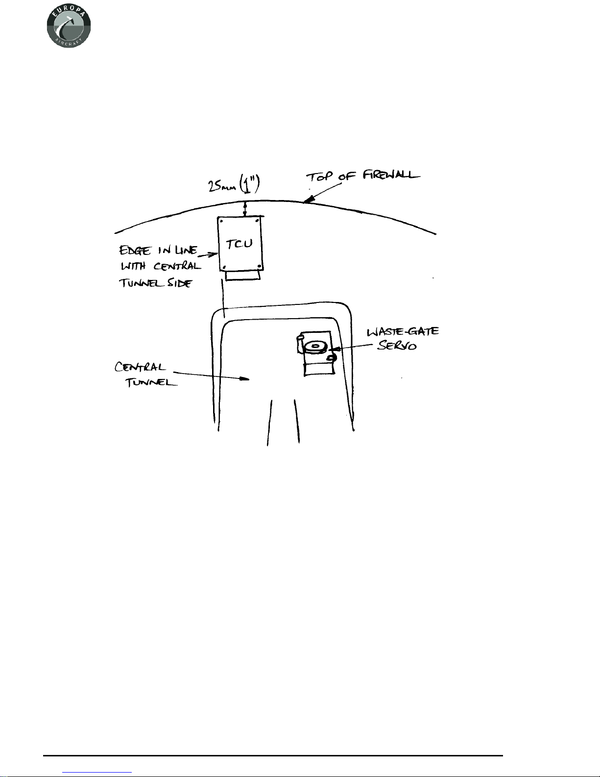
The turbocharger wastegate is controlled by the TCU and operated by the servo motor unit. These
two items have to bepositioned away from sourcesofhigh temperatures. Consequently they are to
be fitted in the cabin on the top of the tunnel right at the front behind the firewall.
Servo motor
The servo motor is mounted horizontally on the right of the tunnel, with the operating cable facing
forwards. The positions shown in figure 3 are suggested but, depending on the equipment in the
instrument panel, you may have to site them elsewhere.
Be careful to take into account the length of the already made up cables which connect the various
engine related components together before making your final decision on their positions.
Page 1 - 2
June 2004 Issue 7 Europa XS Rotax 914 Engine Manual
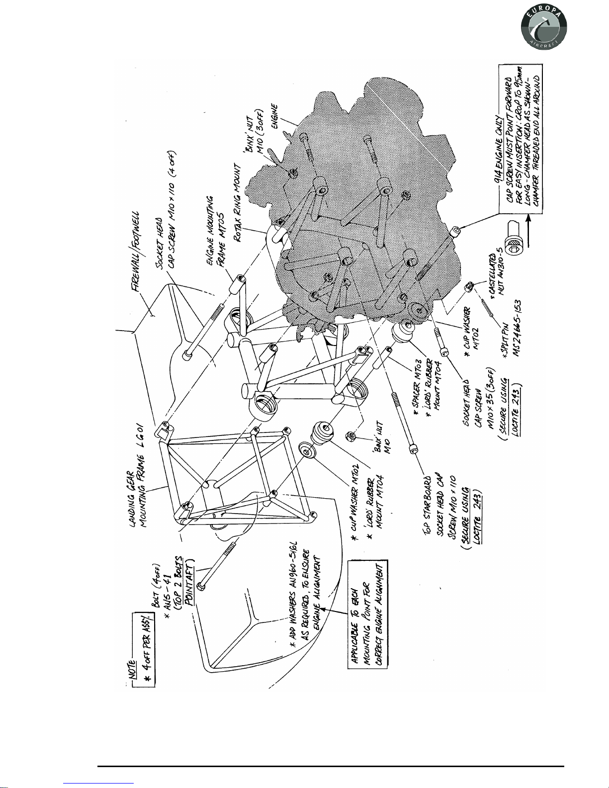
Fig 2. 914 engine installation exploded view.
Europa XS Rotax 914 Engine Manual Issue 7 March 2006
Page 1 - 3
When cutting the necessary holes through the firewall for the various cables, keep them to a
minimum size and use a suitable method of sealing around the cables after they are in place.
Havingpositioned theservomotor, markout themountingholes. FittwoMS21047-4 anchornutson
topofthe tunnel,using TAPK33BS rivets. The unitis mountedwith two spacerson eachAN4-17A
bolt, one W14 spacer, and one shorter spacer made by cutting a W14 in half.
Figure 3. Position of servo motor and TCU. View looking forward.
Turbo control unit
This unit is mounted vertically on firewall on the cabin side, in the position shown in figure 2.
Thefour mountingboltspass throughthe firewallwith thenuts infront ofit. Since the threadlength
of the bolts is rather short it will be necessary to make the appropriate part of the firewall thinner.
Using a 20 mm (3/4") hole saw, carefully drill through the forward skin and foam only. Bond
NAS1169C10 Tinnerman washers into the recess with flox, ensuring that the recessed face of the
washers is kept clear of the flox. Mount the unit with spring washers and M4 nuts.
Page 1 - 4
September 2003 Issue 6 Europa XS Rotax 914 Engine Manual
Pressure sensors
Two pressure sensors are provided with the engine, measuring respectively the static pressure and
the airbox pressure. These sensors need to be mounted with the pressure connection facing
downwards, to avoid any possibility of condensate entering them.
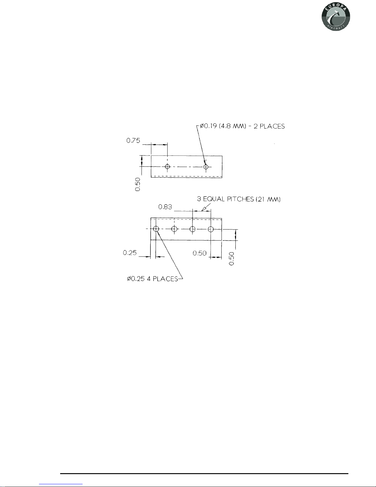
Make up a mounting bracket from the 1" x 1" aluminium angle supplied, drilling it as shown in
figure 4.
Fig 3. Detail of pressure sensor mounting bracket.
This unit isfittedon the engine side of thefirewall- mark a suitable position (notethat the cables to
the TCU are quite short), and drill through the firewall with a 4.8 mm drill. Fit two MS21047-3
anchor nuts on the cabin side, riveting them with TAPK36BS rivets.
Fit the bracketto the firewall with twoAN3-4Abolts. The pressure sensors are fittedto the bracket
with AN4-5A bolts and MS21042-4 stiffnuts.
Connect a length of 4 mm bore PVC tube to each of the pressure sensors. The airbox sensor tube
connects to the unused leg of a nylon “T” piece situated forward of the airbox on the port side. A
water trap is supplied with the engine, and it should be fitted in the line.
The static pressure tube should terminate close to the engine air inlet filter.
Europa XS Rotax 914 Engine Manual Issue 6 September 2003
Page 1 - 5
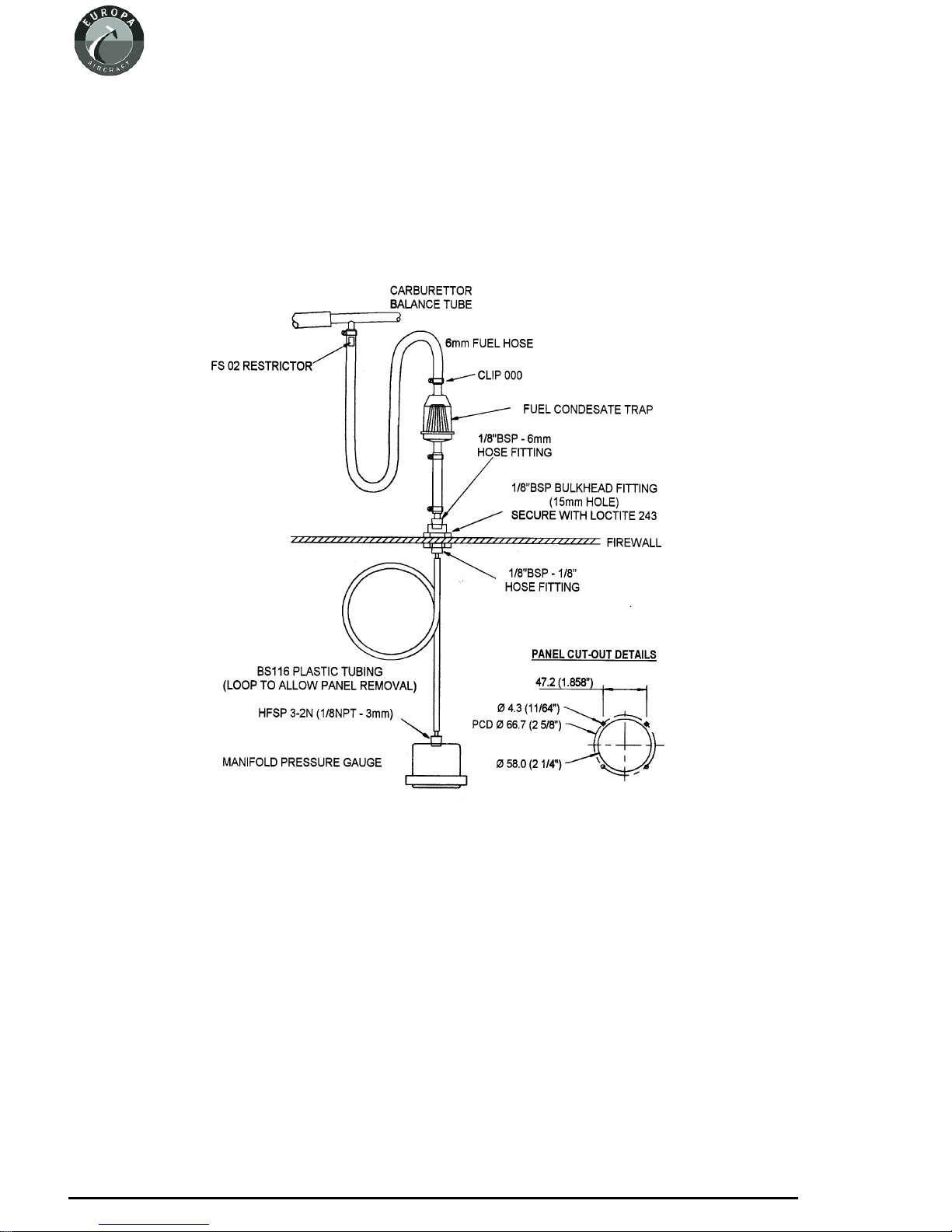
Manifold pressure gauge
A manifold pressure gauge, calibrated to read between 10 in. Hg and 50 in. Hg, is provided, along
with all thenecessaryparts to plumb it into the engine. The position of the gauge issuggestedto be
beside the tachometer.
Refer to the diagram in figure 4 for all the connections.
Fig 4. Manifold pressure gauge connections.
Propeller drive lugs
The engineisnormally delivered with the sixpropeller drive lugs suitableforthe ground adjustable
Warp Drivepropeller suppliedloose. These area light interferencefit inthe propeller flange,with a
relief on the forward part to assist in starting the insertion of them into the flange.
To complete the installationit will be necessary to pull them into position usinga suitable bolt, nut,
and washer,with a spacertube. Ensure thatthe drivelugs are fittedwith no gapbetween the backof
the propeller flange and the drive lug collar.
Page 1 - 6
February 2005 Issue 7 Europa XS Rotax 914 Engine Manual
2. Engine controls
TheRotax 912hastwo independentcarburettors, eachone providingafuel/air mixturetoonepairof
cylinders.
The only mechanical controls required for the carburettors are throttle and choke. There is a
computer controlled turbocharger wastegate control, which varies the boost pressure in response
primarily to demand from throttle position, but limited also by other functions such as RPM, static
pressure, airbox pressure and temperature, etc.
The throttle leverwill be set to give engineoutput varying from 0% to 115% (fullthrottle position).
This poweris available only for5 minutes, normalcontinuous maximum power being100%. Stops
on the carburettors control the 0% and 115% positions, but a gate will need to be included in the
slotted facia plate, through which the throttle lever runs, to set the 100% position. Special purpose
software is used with which to set the throttle stops, details of which are to be found in the Rotax’s
914 Engine Installation Manual
Although there are two independent throttles and chokes, there is only one throttle and one choke
control in the cockpit.
Throttle Control
Asinglelever,protruding througha slotin the centralspine ontop ofthecentral tunnel,provides the
pilot with throttle control. The lever is mounted and pivots in a fibreglass housing fixed to the
underside of the wheel well, and operates two separate cables.
Throttle Lever Housing
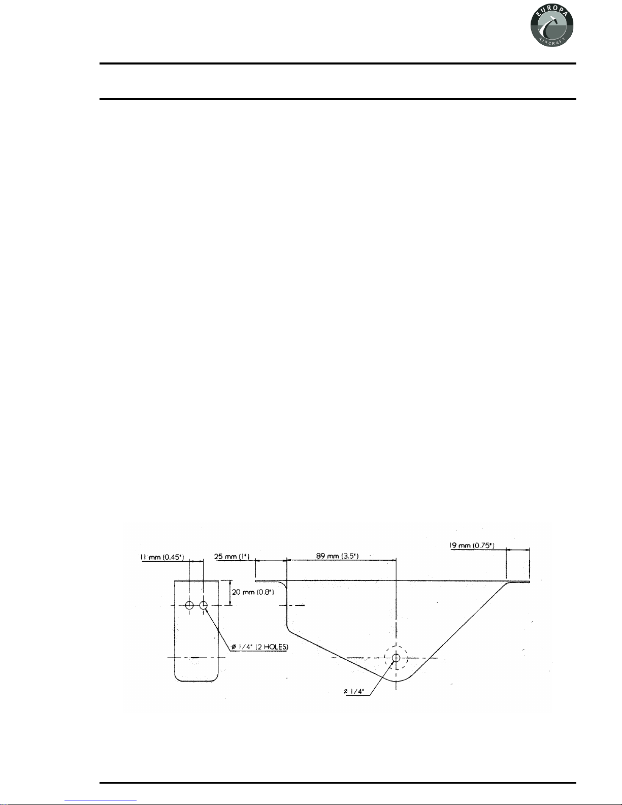
Drill the holes in the throttle lever housing, as shown in figure 1.
Fig 1. Throttle lever housing drilling dimensions.
Europa XS Rotax 914 Engine Manual Issue 9 April 2006
Page 2 - 1
Drillalsoa 4.8mm hole ineach flangeformounting bolts. Open upthe holeon the starboardside of
the housing to allow a socket spanner through.
Assembly
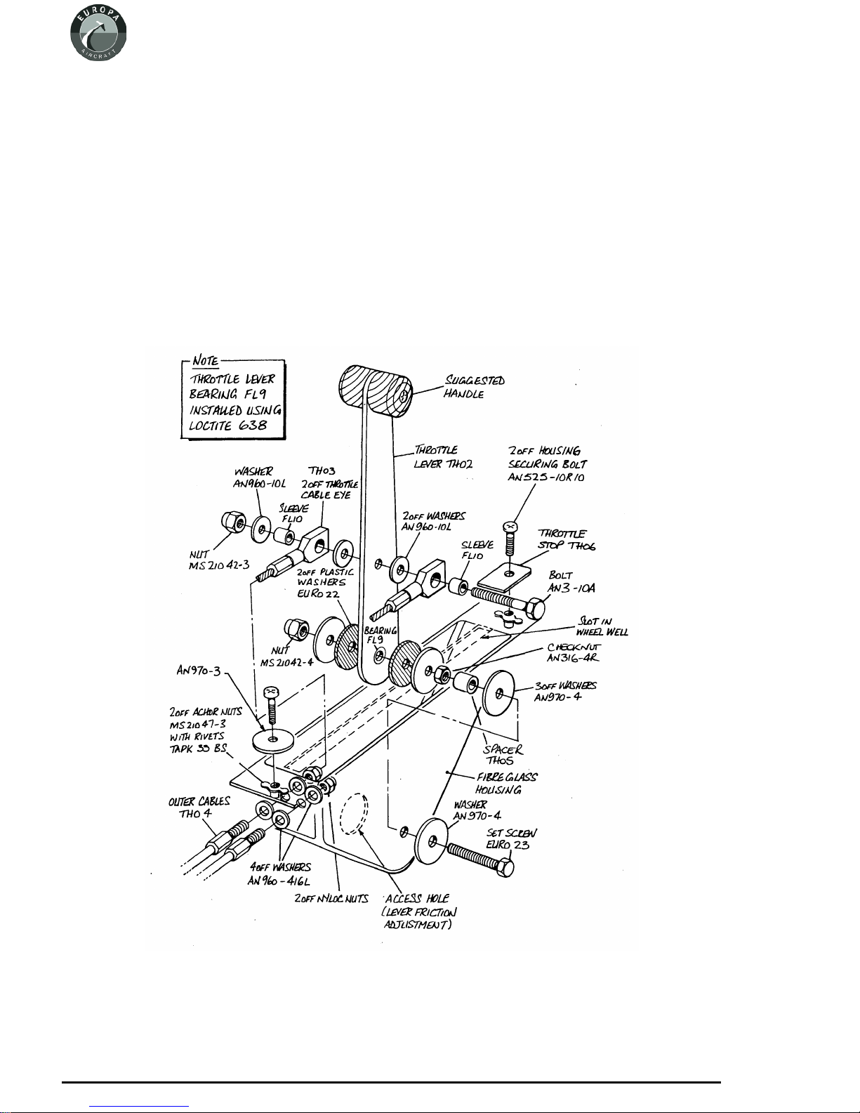
Install the cable outers through the two holes in the housing and clamp them in position using the
nyloc nut with an AN960-416L washer each side of the fibreglass. Assemble the two cables to the
throttle lever according to figure 3 ensuring the end fittings are free to pivot. Thread the cables into
the cable outers, then install the lever into the housing as shown in figure 2, adjusting the lever
friction as desired. The friction should be sufficient to prevent the carburettor throttle lever spring
fromopening thethrottle automatically,andthis canbe doneafter finalassembly.Cover theopening
in the side of the housing to keep dirt out - a suitably sized rubber grommet would be ideal.
Fig 2. Exploded diagram of throttle lever assembly.
Page 2 - 2
November 2004 Issue 8 Europa XS Rotax 914 Engine Manual

Installation
The throttle lever housing should be positioned such that its front face is 380 mm (15") aft of the
firewall. For the monowheel aircraft this will ensure clearance with the main wheel top when it is
retracted. Mark out and cut a slot for the throttle lever in the spine in the centre tunnel then,
checking that full throttle travel is achievable, drill through the flanges for mounting bolts.
For ease of installation attach an MS21047-3 anchor nut to the underside of the housing’s flange at
each end using TLPK 424 BS rivets then, using AN525-10R10 bolts, secure the housing in place.
The front mountingwill use an AN970-3washer, see figure 2, and an AN970-3washer can be used
temporarily to hold the rear of the mounting until it is substituted by the throttle closed stop.
Fit the throttle knob parts TH07 using an AN525-10R10 bolt and MS21042-3 nut to the top of the
throttle lever to complete the installation.
Slot thethrottle cablesthrough the gapbetween the firewalland the uppermounting membersof the
landing gear frame, securing them to the frame with tie wraps to prevent chafing. Remove and
discard the straight cable-outer receptacle provided on each carburettor and in its place insert the
throttle cable’s threadedend. Use one check nut each sideof the bracket to clamp thecable-outerin
place. The cablesmay seemexcessivelylong, butthis istoallow largebend radiiinthe enginebay to
ensure minimum friction.
Each throttle cable should emerge through the metal firewall onthe opposite side to the carburettor
that it will control. Loop the cable up and aft towards the centre of the firewall, then down into the
bracket of the appropriate carburettor. Loosely secure the two cables where they cross.
Insert thecable inner into thenipple on the carburettorthrottlelever, which is sprungto its full open
position.Settingthethrottleleverin thecockpitback about2-3cm (1")fromitsfullforwardposition,
screw bothnipples tight onthe cables.Checkfor fullthrottle movement, makingany adjustments as
required,thenseal the openhole inthe throttle leverhousing toprevent anythingthrown up fromthe
wheel from entering.
Throttle closed stop
The addition of a throttle-closed stop is important to avoid the possibility of excess tension on the
throttle cable causing loss of throttle control. Following the method below, prepare a plate, made
from 3 mm (1/8”) aluminium, 50 mm (2”) wide. With the throttle closed, and the slow running
adjustment correctly set atthe carburettors, measure the distance from the rear ofthe throttlelever,
whereit protrudesabovethe topofthe tunnel,tothecentreof the rear4.8mm(3/16”)mounting hole.
The plate length will be 6 mm (1/4”) more than this measurement. Drill the plate 6 mm (1/4”) from
one end, bond with Redux to the tunnel, and bolt with an AN525-10R10 bolt.
Note: You should set the throttle closed stop such that a fully warmed engine idles at 1200 1400rpm. Althoughthe engineidles moresmoothly at 1600rpm or more,when landingthe aircraft
you will benefit from minimal residual thrust.
Europa XS Rotax 914 Engine Manual Issue 9 April 2006
Page 2 - 3

Choke Control
The two chokecontrol cables are swaged togetherinto the choke operating knob butrun in separate
outer sleeves which are swaged into a housing.
Installation
Drill a 13 mm (
1
“)
2
diameter hole as low
as possible in the
back face of the
throttlelever spineof
thecockpit moulding
for the cable outer
assembly to go
through. See figure
3.
Push the threaded
portion of the
cable-outer housing
through the hole and
Fig 3.Position of choke control.
clampit inplace with
the lock washer and
knurled nut.
Note : As it can be difficult to insert the two cables into their respective outers, remove the plastic
knob instead leaving the cables installed when mounting the outer to the cockpit module.
The choke cables should emerge through the metal firewall as do the throttle cables. Loop these
cables forward over the top of the engine so that they enter the 90° elbow guides mounted on the
carburettor from the front. Rotate the elbows so that the cables enter them as straight as possible.
Push the cables into the carburettor cable guides and secure the cablesto the choke levers using the
solderless nipples. Ensure that the choke knob is fully in and the choke levers are fully down at the
same time and that full choke movement can be achieved.
Squeezesilicone RTV aroundthe cableswhere theycome throughthe firewalland securethemwith
a cable tie to the engine mounting frame to prevent them from chafing.
To ensurethatthe cables don’t come outof their guides, use lockingwire wrapped aroundthe cable
outer and also the cable guides.
Page 2 - 4
April 2006 Issue 9 Europa XS Rotax 914 Engine Manual
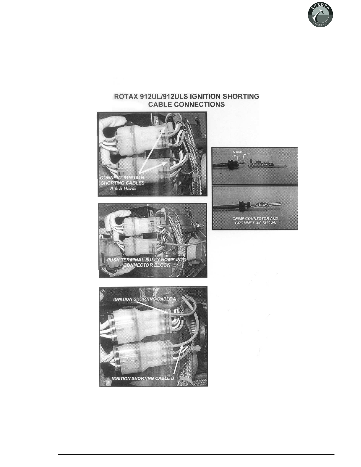
Ignition shorting cables connection
RecentRotax engineshave modifiedignition shortingcable connections. The photographsin figure
4 are self-explanatory.
Fig 4. Ignition shoring cables connection.
Europa XS Rotax 914 Engine Manual Issue 10 November 2007
Page 2 - 5

INTENTIONALLY BLANK
Page 2 - 6
November 2007 Issue 10 Europa XS Rotax 914 Engine Manual
3. Oil tank
Oil Tank Mounting Bracket
The oiltank isto bemounted tothe front ofthe starboard footwellusing a steelbracket. To makethe
mounting bracketfirst mark outand cutout the steelsheet LB01 according tothe drawing atthe end
of this chapter. Next, bend the central wide portion intoa curve to match the outside of the oil tank.
This can be accomplished by running the metal backwards and forwards across the corner of a
wooden bench whilst applying a bending force on it.
Finally, bend the lugs each side of the curved portion so that the two narrow flanges can sit flat
against the footwell front face. See figure 1. Bending can be done by clamping the steel between
lengths of wood in a vice. Try to avoid a sharp bend radius, a 10mm (3/8") radius is ideal.
Makea 90°anglebracketfromthenarrowstripshownon thetemplateandrivet itto thetopright port
side using TLPD424BS rivets -it should fit on top of the footwell.
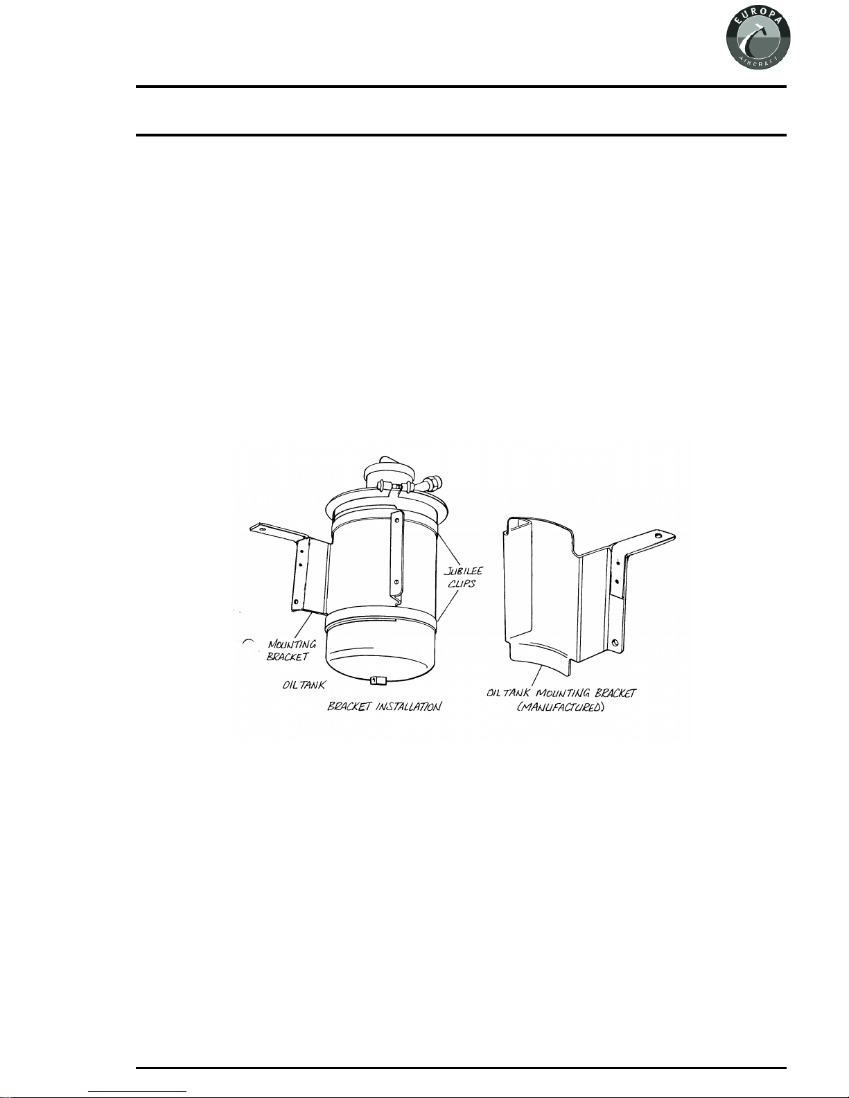
Fig 1. Oil tank mounting bracket.
Bracket installation
Arranging the bracket with the upper lug fitting under the oil tank lid, fasten the bracket to the tank
usingthetwonumber6X sizejubileeclips. Keeptheclamps awayfromtheradiusofthe bracket.
Withthe engineand lowercowlinginplaceposition theoil tankand bracketontothe frontface ofthe
starboard side footwell. Position the tank so that there is reasonable clearance from boththeengine
and cowling.
Europa XS Rotax 914 Engine Manual Issue 4 September 2001
Page 3 - 1
 Loading...