

EuroMobile EH7510 User Manual
EH7510
Industrial Managed Ethernet Switch
User Manual
Version 1.0
October, 2011
TEL: +7 (812) 331-75-76
8 800 555-75-76
http://www.euromobile.ru
info@euroml.ru

Atop Industrial Managed Ethernet Switch
EH7510
User Manual V 1.0
ii
Important Announcement
The information contained in this document is the property of Atop Technologies, Inc. and is
supplied for the sole purpose of operation and maintenance of Atop Technologies, Inc
products. No part of this publication is to be used for any other purposes, and it is not to be
reproduced, copied, disclosed, transmitted, stored in a retrieval system, or translated into
any human or computer language, in any form, by any means, in whole or in part, without
the prior explicit written consent of Atop Technologies, Inc.
Published by
Atop Technologies, Inc.
2F, No. 146, Sec. 1, Tung-Hsing Rd.
Jubei, Hsinchu 30261
Taiwan, R.O.C.
Tel: 886-3-5508137
Fax: 886-3-5508131
www.atop.com.tw
Copyright © 2011 Atop Technologies, Inc. All rights reserved.
All other product names referenced herein are registered trademarks of their respective
companies.

Atop Industrial Managed Ethernet Switch
EH7510
User Manual V 1.0
iii
Table of Contents
Preface ........................................................................ 1
Chapter 1: Introduction ................................................ 2
1.1 What is a Managed Industrial Switch ........................................... 2
1.2 Software Features ....................................................................... 3
1.3 Hardware Features ...................................................................... 4
1.4 Power Requirements ................................................................... 5
1.5 Environmental Limitations ............................................................ 5
1.6 LED Indicators ............................................................................. 5
Chapter 2: Configuring with a Web Browser ................ 6
2.1 Web-based Management Basics ................................................. 6
2.1.1 Default Settings ....................................................................... 6
2.1.2 Login Process and Main Window Interface ............................. 6
2.2 Information ................................................................................... 8
2.2.1 Basic ....................................................................................... 8
2.2.2 Console ................................................................................... 9
2.2.3 Power Status........................................................................... 9
2.2.4 Protocol Status ...................................................................... 10
2.3 Administration ............................................................................ 11
2.3.1 System Settings .................................................................... 11
2.3.2 Password .............................................................................. 12
2.3.3 IP Settings ............................................................................. 13
2.3.4 Forwarding and QoS ............................................................. 14
2.3.4.1 CoS Mapping ................................................................... 17
2.3.4.2 ToS/DiffServ Mapping ....................................................... 18
2.3.5 Mirror Port ............................................................................. 19
2.3.6 System Time and SNTP ........................................................ 20
2.3.7 Modbus Setting .................................................................... 21
2.3.8 PTP Setting ................................................................ ........... 24
2.4 Port ............................................................................................ 26
2.4.1 Port Status ............................................................................ 26
2.4.2 Port Statistics ........................................................................ 27
2.4.3 Port Control ................................ ................................ ........... 28
2.5 Trunking ..................................................................................... 29

Atop Industrial Managed Ethernet Switch
EH7510
User Manual V 1.0
iv
2.5.1 LACP .................................................................................... 29
2.5.2 Trunking ................................................................................ 30
2.6 Unicast/Multicast MAC ............................................................... 31
2.6.1 MAC Address Table .............................................................. 32
2.6.2 Add Uni/Multicast MAC ......................................................... 32
2.6.3 Filter MAC ............................................................................. 33
2.7 GARP/GVRP/GMRP .................................................................. 34
2.7.1 Multicast Group Table ........................................................... 34
2.7.2 GARP .................................................................................... 35
2.7.3 GVRP .................................................................................... 36
2.7.4 GMRP ................................................................................... 37
2.8 IGMP/IP Multicast ...................................................................... 38
2.8.1 IGMP/IP Multicast Table ........................................................ 38
2.8.2 Static IP Multicast ................................................................. 39
2.8.3 IGMP ..................................................................................... 41
2.8.4 IGMP Statistics ..................................................................... 42
2.9 SNMP ........................................................................................ 43
2.9.1 Community Strings ................................................................ 44
2.9.2 Trap Receivers ...................................................................... 45
2.9.3 SNMPv3 Users ..................................................................... 45
2.10 Spanning Tree ......................................................................... 46
2.10.1 Spanning Tree ..................................................................... 47
2.10.2 Spanning Tree Port ............................................................. 49
2.11 VLAN ....................................................................................... 50
2.11.1 VLAN Mode ......................................................................... 52
2.11.2 VLAN TABLE ....................................................................... 54
2.11.3 VLAN Setting ....................................................................... 55
2.11.4 VLAN PVID ......................................................................... 57
2.11.5 Example of using 802.1Q VLAN .......................................... 58
2.12 Port Security ............................................................................ 59
2.12.1 Static Port Security ............................................................. 59
2.12.2 Add Static MAC ................................................................... 61
2.12.3 802.1x and Radius .............................................................. 62
2.12.4 802.1.x ............................................................................... 63
2.12.5 802.1x Port.......................................................................... 64
2.13 ERPS/Ring .............................................................................. 65
2.13.1 DIP Switch .......................................................................... 65

Atop Industrial Managed Ethernet Switch
EH7510
User Manual V 1.0
v
2.13.2 ERPS .................................................................................. 67
2.13.2.1 UERPS Settings (optional) ............................................. 71
2.13.3 iA-Ring ................................................................................ 73
2.13.4 Compatible-Ring ................................................................. 75
2.13.5 U-Ring ................................................................................. 76
2.14 LLDP ........................................................................................ 78
2.14.1 LLDP ................................................................................... 78
2.14.2 Neighbors ........................................................................... 79
2.15 System Warning ...................................................................... 80
2.15.1 Warning Event Selection ..................................................... 80
2.15.2 Alert Warning Events ........................................................... 82
2.15.3 SMTP Settings .................................................................... 83
2.16 Diagnosis ................................................................................. 84
2.16.1 Ping ..................................................................................... 85
2.17 System Log .............................................................................. 86
2.17.1 Syslog ................................................................................. 86
2.17.2 Event Log ............................................................................ 87
2.18 System ..................................................................................... 89
2.18.1 Backup/Restore .................................................................. 89
2.18.2 Firmware Upgrade .............................................................. 90
2.18.3 TFTP ................................................................................... 91
2.18.4 Factory Default .................................................................... 92
2.18.5 Reboot ................................................................................ 93
Chapter 3: Configuring with a Serial Console ............ 94
3.1 Serial Console Setup ................................ ................................ . 94
3.2 Command Line Interface Introduction ........................................ 95
3.3 General Command .................................................................... 97
3.4 Command Example ................................................................... 97
3.4.1 Administration Setup using Serial Console ........................... 98
3.4.2 Spanning Tree Setup using Serial Console .......................... 99
Chapter 4: SwitchView & Topolog Diagram ............. 100
4.1 SwitchView .............................................................................. 100
4.2 Firmware Upgrade ................................................................... 101
4.3 Topology Diagram .................................................................... 102
Appendix A. ModBus Management Memory Map ... 103

Atop Industrial Managed Ethernet Switch
EH7510
User Manual V 1.0
vi
Glossary ................................................................... 113

Atop Industrial Managed Ethernet Switch
EH7510
User Manual V 1.0
1
Preface
This manual contains some advanced network management knowledge, instructions,
examples, guidelines, and general theories; designed to help users manage EH7510 and
use its software, a background in general theory is a must when reading it. Please refer to
the Glossary for technical terms and abbreviations.
Who Should Use This User Manual
This manual is to be used by qualified network personnel or support technicians who are
familiar with network operations; it might be useful for system programmers or network
planners as well. This manual also provides helpful and handy information for first time
users. For any related problems please contact your local distributor, should they be unable
to assist you, please redirect your inquiries to www.atop.com.tw.
Supported Platform
This manual is designed specifically for the EH7510 switch series.
Warranty Period
Atop technology provides a limited 5-year warranty for EH7510 switches.

Atop Industrial Managed Ethernet Switch
EH7510
User Manual V 1.0
2
Chapter 1: Introduction
1.1 What is a Managed Industrial Switch
Atop’s EH (Ethernet Switching Hub) 7510 is a powerful managed industrial switch; a switch
is referred to as an OSI Layer 2* bridging device. Unlike an “unmanaged” switch, which is
normally found in homes or in SOHO environments and runs in “auto-negotiation” mode,
each port on a “managed switch” can be configured for its link bandwidth, priority, security,
and duplex settings. The managed switches can be managed by web browsers, Telnet, or
serial console. Since every single port can be configured to specific settings, network
administrators can better control the network and maximize network functionality.
EH7510 is an industrial switch (as opposed to a commercial switch); a commercial switch
simply works in a comfortable office environment. However, an industrial switch like EH7510
is designed to perform in harsh industrial environments, i.e., extreme temperature, high
humidity, dusty air, potential high impact or the presence of potentially high static charges.
EH7510 works fine even in these environments.
Atop EH7510 is designed to provide faster, securer, and more stable networks. One
advantage that makes EH7510 a powerful switch is that it supports technologies including
ERPS, iA-Ring, Compatible Ring and RSTP. These technologies provide better network
reliability, and decreases recovery time down to less than 20 ms.
EH7510 Ethernet Switch supports a wide range of IEEE standard protocols. This switch is
excellent for keeping systems running smoothly, reliable for preventing system damage or
losses, and friendly to all levels of users. The goal of this innovative product is to bring users
a brand new network-management experience.
*Note:
Throughout the manual, the symbol * indicates that more detailed information of the subject
will be provided at the end of this book.

Atop Industrial Managed Ethernet Switch
EH7510
User Manual V 1.0
3
1.2 Software Features
Atop’s iA-Ring ERPS Technologies
- Improve network redundancy
- Fast recovery time (<20ms)
- iA-Ring Provides Ring Coupling and Dual Homing
Three User Friendly Interfaces Supported
- Web browser
- Telnet Console
- Serial Console
SNMP v1/v2/v3 Supported (with MD5 Authentication and DES encryption)
RSTP Support
QoS Traffic Regulation Supported
IGMP supported (with IGMP snooping)
Alarm System Supported (with E-mail Notification)
IEEE 802.1x (with RADIUS) Supported for Network Access Control
LACP Supported
Compatible Ring
U-Ring
SNTP
PTP
GVRP
GMRP
Spanning Tree
LLDP
Atop Industrial Managed Ethernet Switch
EH7510
User Manual V 1.0
4
1.3 Hardware Features
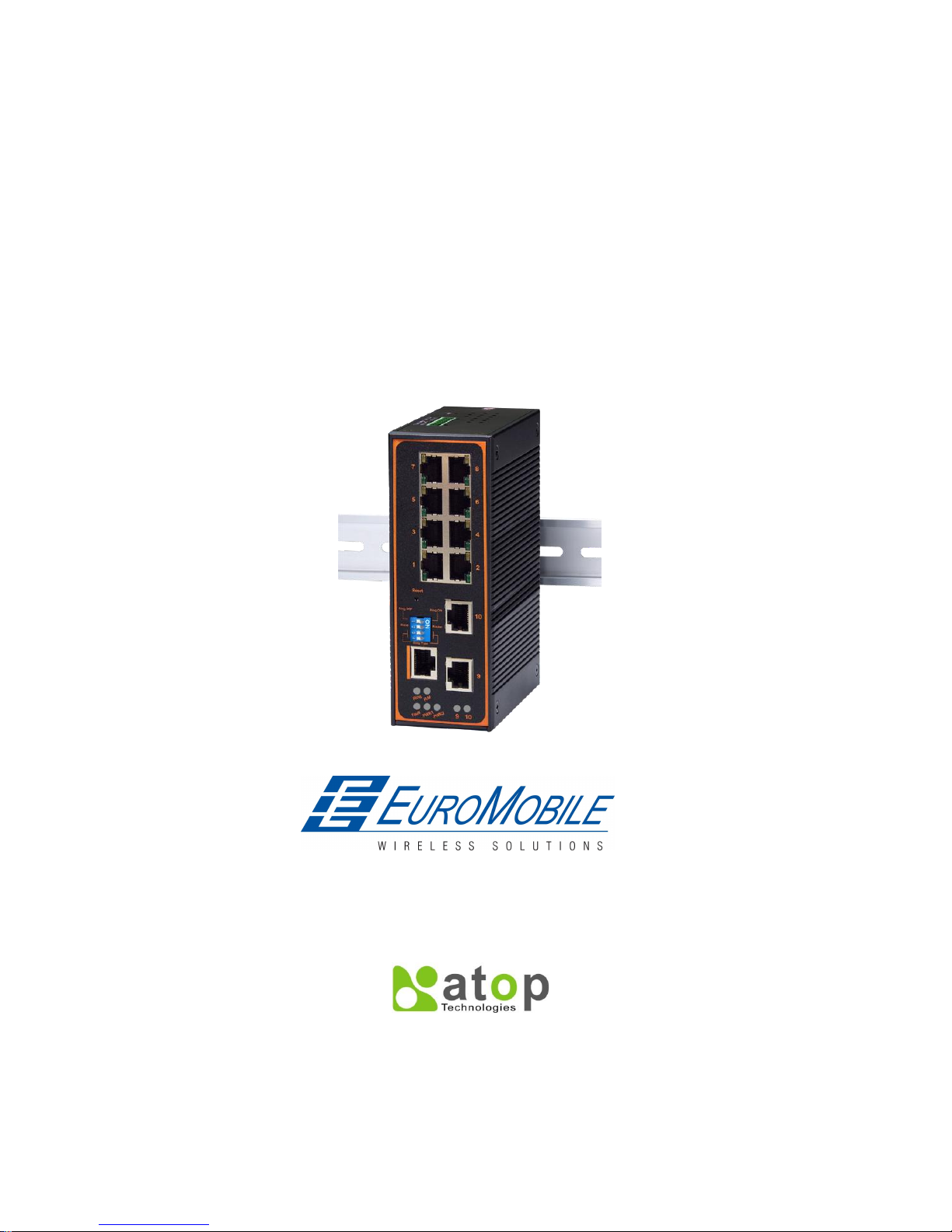
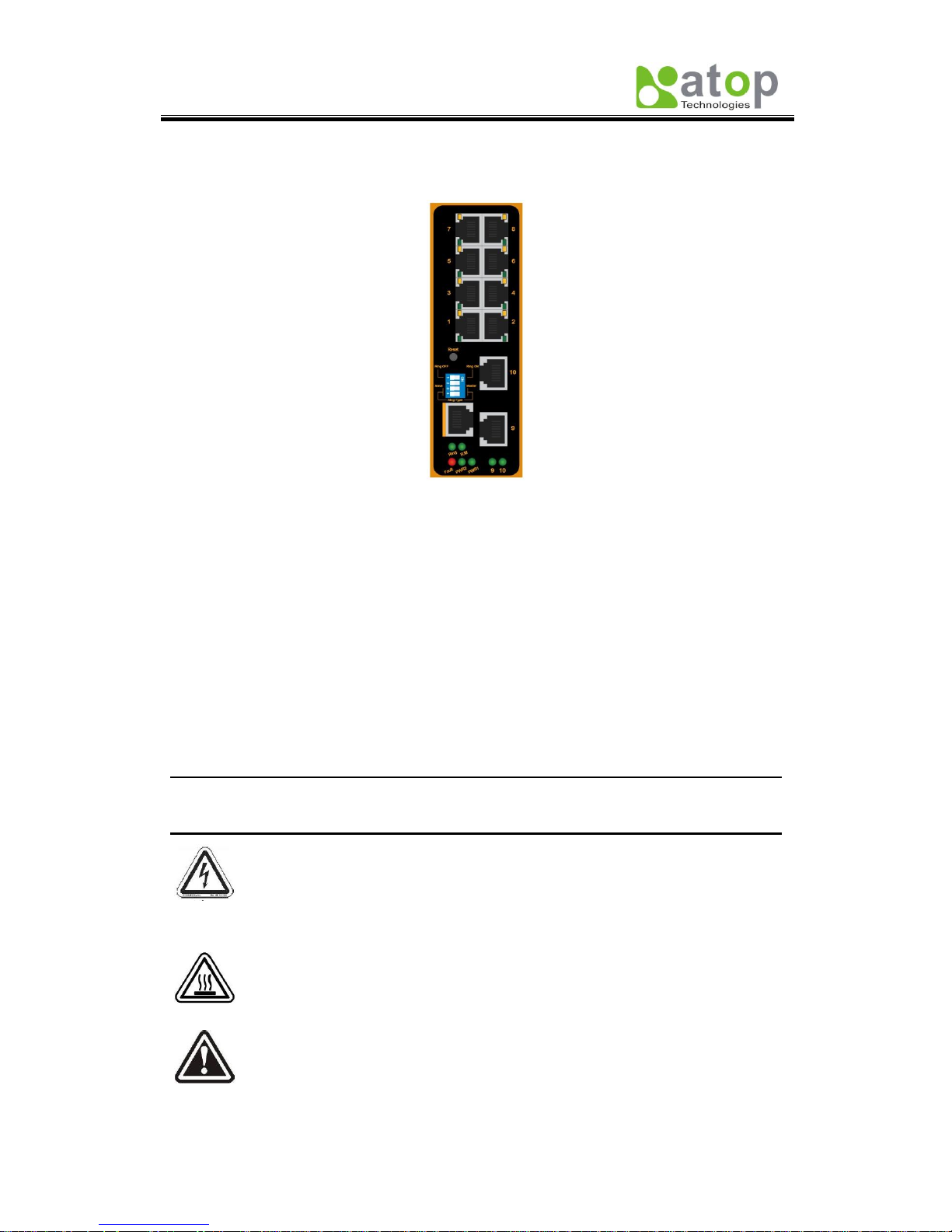
Device Appearance, Fig. 1.1:
Fig. 1.1
Dimensions: 53.4 mm (W) x 119.9 mm (D) x 145.7 mm (H)
Weight: approx 1.1kg
8 x 10/100M Ethernet ports (Port # 1~8)
2 x Gigabit Ethernet ports or 2 x Fiber ports (Port # 9~10)
1 x Serial Console Port
1x4 DIP switch
LED indicators
1 x Reset button
Caution
An approved Optical transceiver should be chosen to plug into the slot.
Never install or work on electrical or cabling during periods of lighting activity.
Never connect or disconnect power when hazardous gases are present.
WARNING: Disconnect the power and allow to cool 5 minutes before touching.
Caution: CLASS 1 LASER PRODUCT. Do not stare into the laser!

Atop Industrial Managed Ethernet Switch
EH7510
User Manual V 1.0
5
1.4 Power Requirements
Dual Inputs: 12~48 Volts DC
Input Current: 1.2A Max.
1.5 Environmental Limitations
Operating Temp: -40°C ~ 80°C (or -40°F ~ 176°F)
Storage Temp: -40°C ~ 85°C (or -40°F ~ 185°F)
Relative Humidity (non-condensing): 5 to 95 %
Note: for UL policy, the maximum operating temperature is 60°C and the human
body can tolerate a maximum of 70°C.
1.6 LED Indicators
Port LED:
Green Light: Steady- Link up, Blinking- Data transmitting
Orange Light: on- full duplex, off- half duplex (refer to section Port)
PWR 1: Indicates power 1 status
PWR 2: Indicates power 2 status
Fault: Indicates Fault status
R.M: Indicates Atop’s Ring Master Status (Refer to section ERPS/Ring)
Ring: Indicates Atop’s Ring Status (Refer to section ERPS/Ring)

Atop Industrial Managed Ethernet Switch
EH7510
User Manual V 1.0
6
Chapter 2: Configuring with a Web Browser
This chapter explains how to access EH7510 for the first time. There are three ways to
configure this Ethernet Switch:
1. Web browser
2. Telnet console
3. Serial console
The web browser and telnet console methods allow users to access the switch over the
Internet or the Ethernet LAN, while the serial console method requires a serial cable
connection between the computer and the switch; there are only a few differences among
these three methods.
2.1 Web-based Management Basics
Users can access EH7510 easily by their web browsers (Internet Explorer 7.0 and Mozilla
Firefox 3.5.7 or later versions recommended). We will proceed to use a web browser to
introduce EH7510’s functions; this web console interface is user-friendly.
2.1.1 Default Settings
Below there is a list of default factory settings; this information will be used during the login
process..
IP Address: 10.0.50.1
Subnet Mask: 255.255.0.0
Default Gateway: 10.0.0.254
User Name: admin
Password: NULL (leave it blank)
2.1.2 Login Process and Main Window Interface
Before the user access EH7510 switch’s configuration they have to log in; this can be done
in 3 simple steps.
1. Launch a web browser.
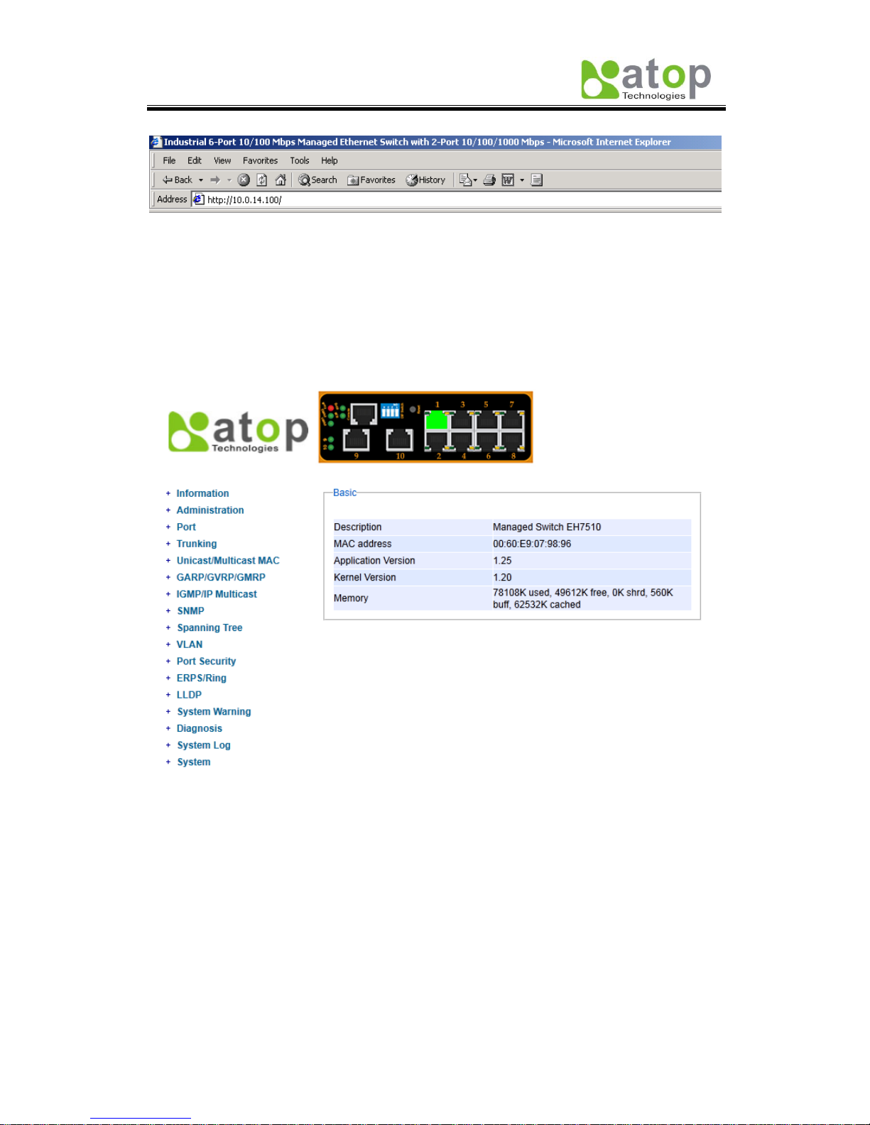
2. Type the switch’s IP address (e.g. https://10.0.50.48), (next page, Fig. 2.1).
Atop Industrial Managed Ethernet Switch
EH7510
User Manual V 1.0
7
Fig. 2.1
3. Key in the username and password on the login window, and click “OK” to login.
*Note: Please take care on configuring the IP in your PC’s Settings when pairing the switch. *
After the login process, the main interface will show up, which should look as Fig. 2.2. The
main menu (left side of the screen) provides the links at the top level of the menu hierarchy
and allows them to be expanded to display lower level links. Note that in this case the port 1
is highlighted in green; this shows that the port is being connected to a LAN cable. Detailed
explanations of each sub-section will be addressed later as the need arises.
Fig. 2.2
Atop Industrial Managed Ethernet Switch
EH7510
User Manual V 1.0
8
2.2 Information
To help users be familiar with the device, the Information section provides important details
of it; this is also the main welcoming screen once the user has logged in. The details make it
easier to identify different devices connected to the network; they are divided into four
sections.
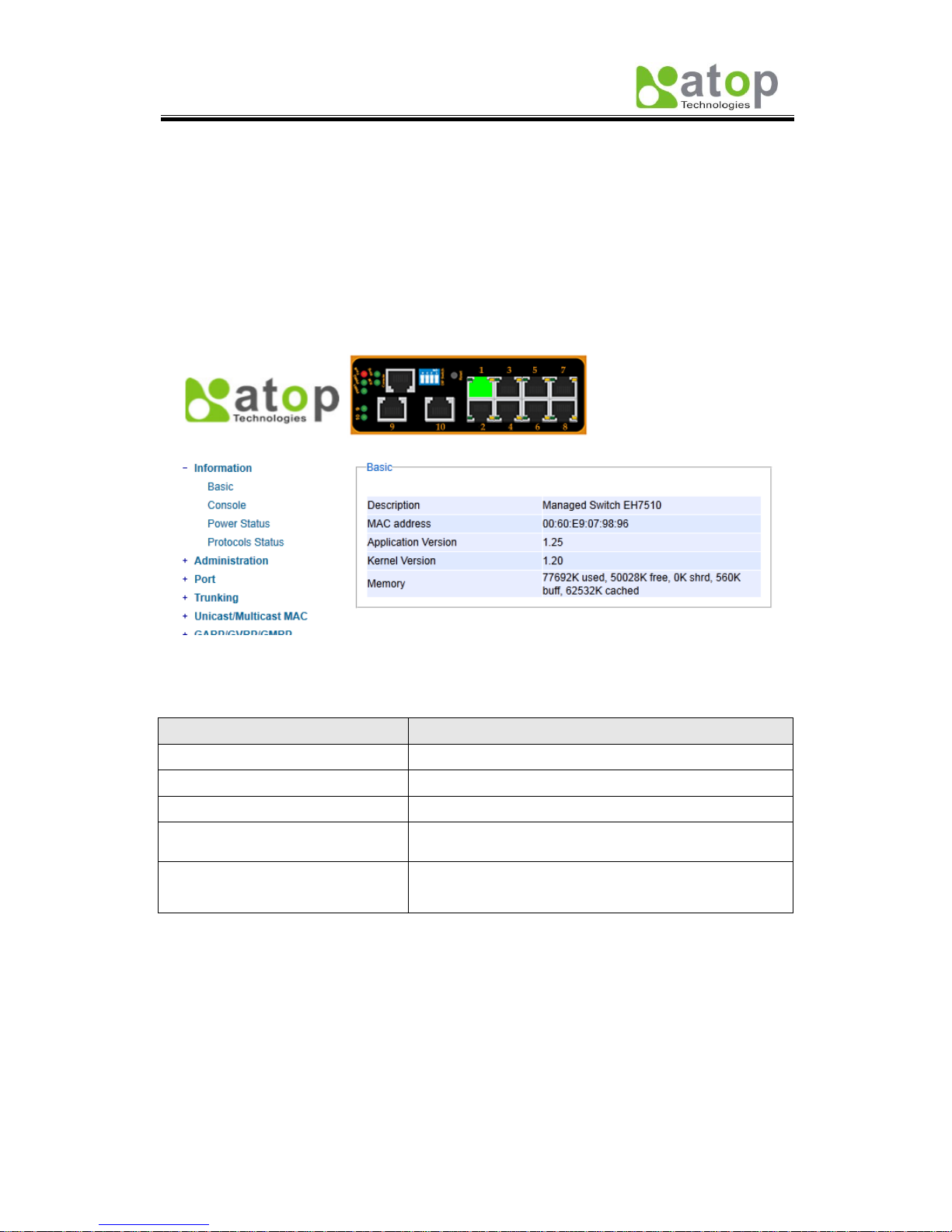
2.2.1 Basic
An introduction to the equipment and net is done in this section, Fig. 2.3.
Fig. 2.3
Table 2.1
Label
Description
Description
Describes the model type of current device.
MAC address
Indicates MAC address* (See Appendix A).
Application Version
States current Application version of the device.
Kernel Version
Shows current Kernel Version of the device.
Memory
Shows current RAM’s size availability also shows the
cached and shared memory.
Atop Industrial Managed Ethernet Switch
EH7510
User Manual V 1.0
9
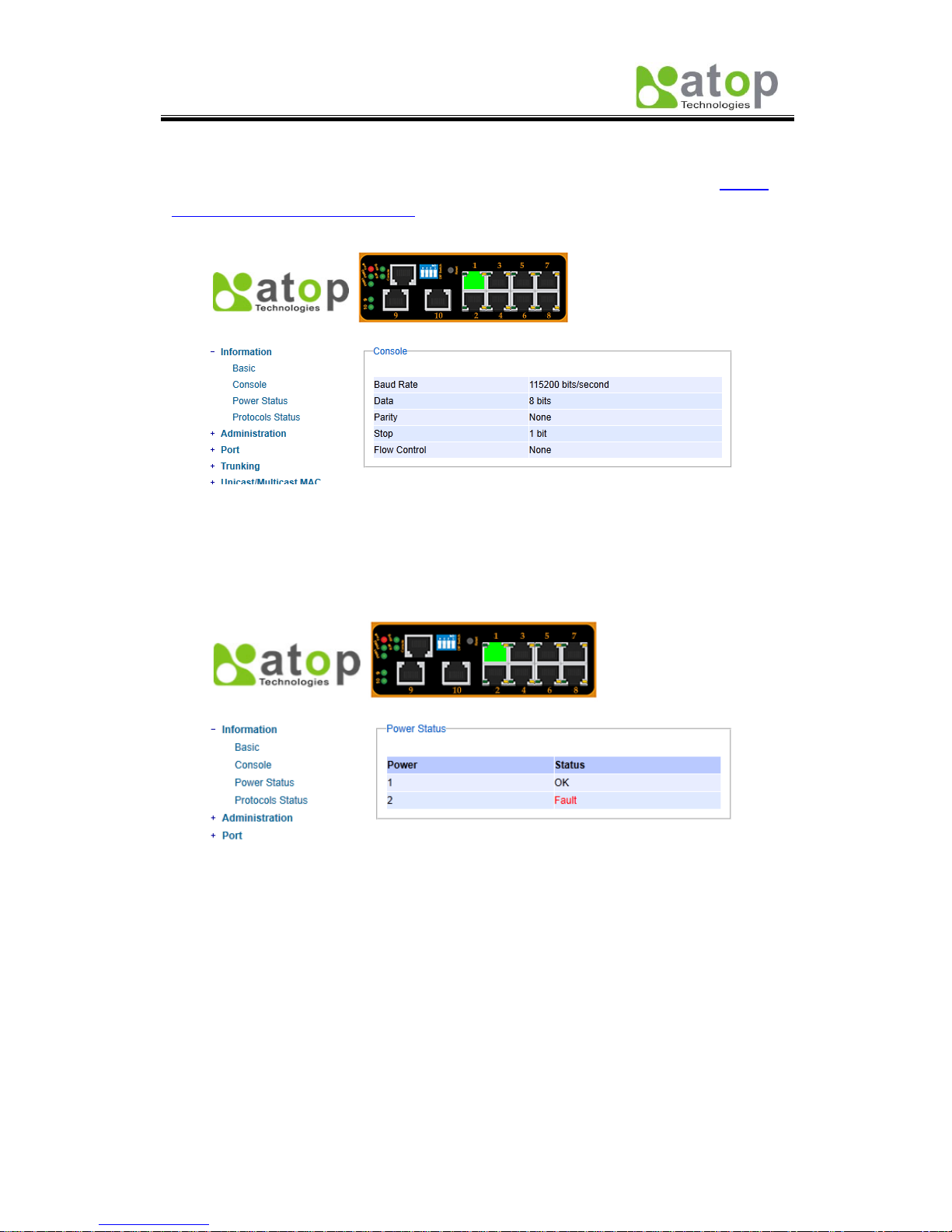
2.2.2 Console
In this chapter, we use a web browser for configuring the switch. However, there is a specific
page for the serial console method. The Console option is only for serial console; it
indicates the connection parameters related to the method.
Fig. 2.4
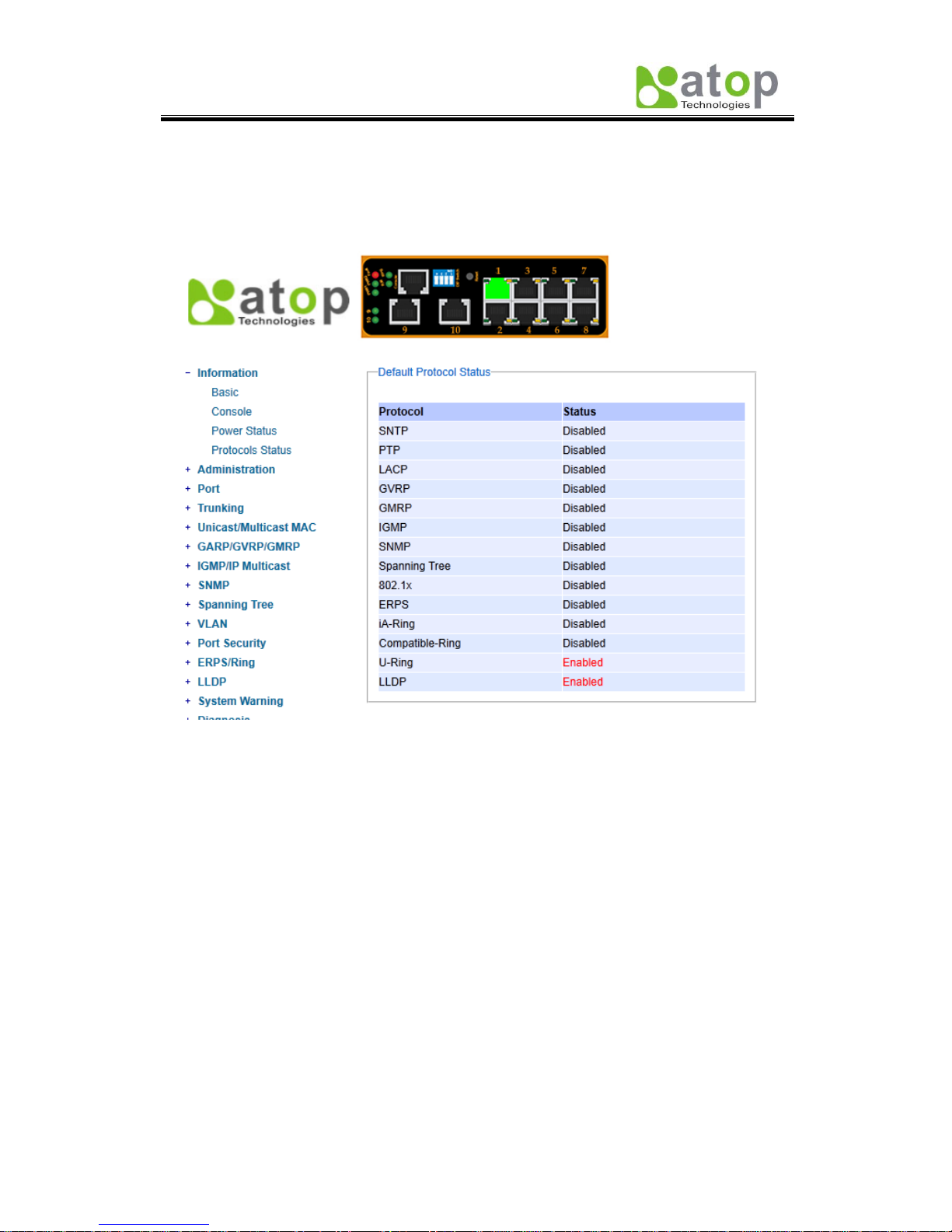
2.2.3 Power Status
EH7510 Managed Switch has dual VDC power inputs; Fig. 2.5 below, shows the status of
each power input.
Fig. 2.5
Atop Industrial Managed Ethernet Switch
EH7510
User Manual V 1.0
10
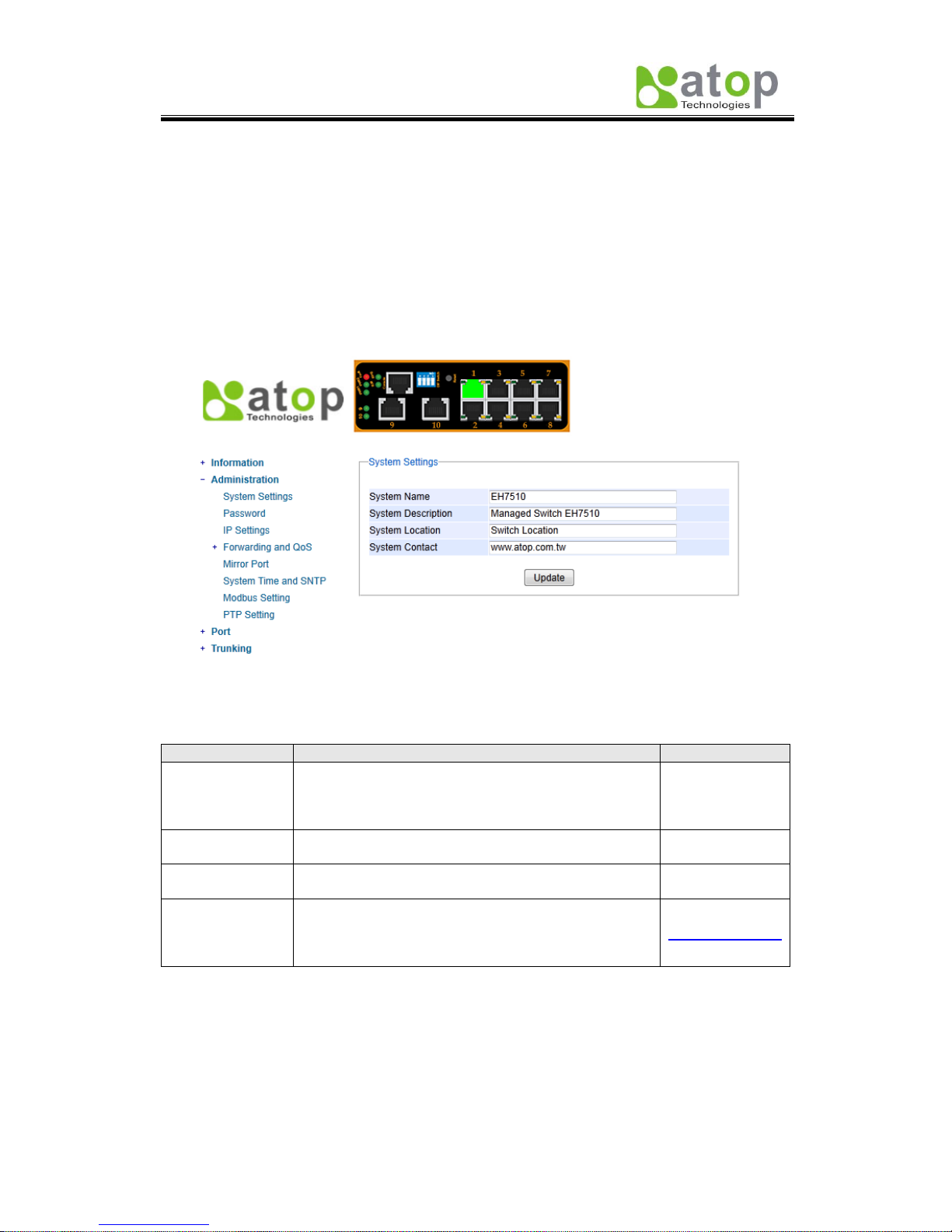
2.2.4 Protocol Status
Reports an overall status of each protocol; while users can view status all at once here,
detailed explanations of each protocol and methods will be provided in later sections, Fig.
2.6.
Fig. 2.6
Atop Industrial Managed Ethernet Switch
EH7510
User Manual V 1.0
11
2.3 Administration
Here users will be able to make changes on System Settings, Password, IP Settings,
Forwarding and QoS, Mirror Port, System Time/SNTP, Modbus Setting and PTP
setting.
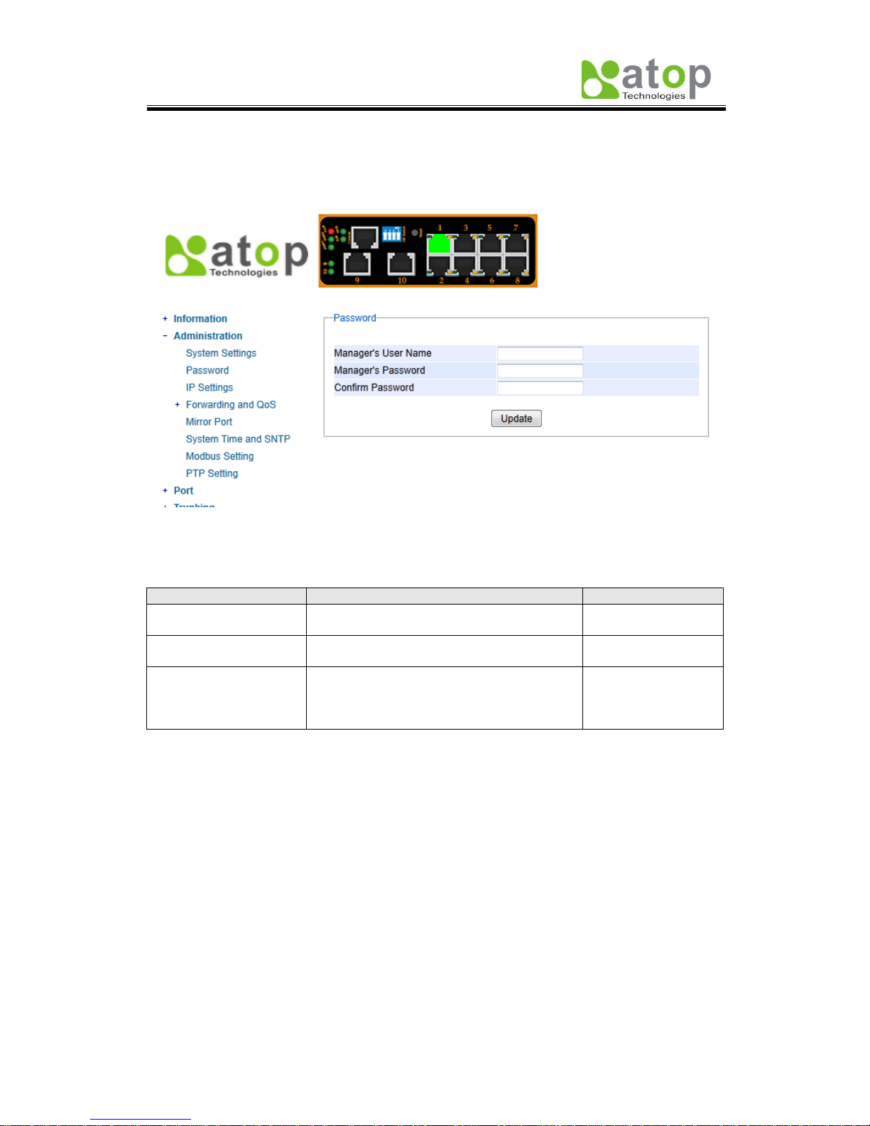
2.3.1 System Settings
Users can enter system’s details here; this information can help identify one specific switch
among all the devices in the network, (Fig. 2.7).
Fig. 2.7
Table 2.2
Label
Description
Factory Default
System Name
Specifies a particular role or application of different
switches. The name entered here, will also be shown
in Switch View and Device View.
Max. 63 Characters.
EH7510
System
Description
Detailed description of the unit.
Max. 63 Characters.
Managed Switch
EH7510
System
Location
Locations of different switch units.
Max. 63 Characters.
Switch Location
System Contact
Provides contact information for maintenance. Enter
the name of whom to contact in case a problem
arises.
Max. 63 Characters.
www.atop.com.tw
Atop Industrial Managed Ethernet Switch
EH7510
User Manual V 1.0
12
2.3.2 Password
Although no password is set for the device when it is manufactured, users can make
changes to assure overall system security, Fig. 2.8.
Fig. 2.8
Table 2.3
Label
Description
Factory Default
Manager’s User name
User’s Name.
Max. 15 Characters.
NULL
Manager’s Password
Password.
Max. 15 Characters.
NULL
Confirmed Password
Re-type the Password. This has to be
exactly as the password entered in the
above field.
Max.15 Characters.
NULL
Atop Industrial Managed Ethernet Switch
EH7510
User Manual V 1.0
13
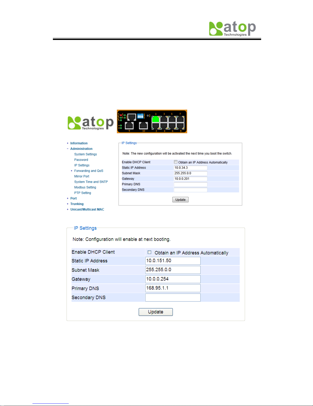
2.3.3 IP Settings
In this section, users may modify IP address functions to reconfigure the switch’s network
settings. Users can choose to enable DHCP (Dynamic Host Configuration Protocol)* here.
This function can obtain an IP address automatically; it provides automatic configuration and
eliminates the need for intervention by the administrator. Users can also opt to set up the IP
address and related fields manually; after each update, a reboot will be required before the
new settings are effective, Fig. 2.9.a.
Fig. 2.9.a
Fig. 2.9.b *Example*

Atop Industrial Managed Ethernet Switch
EH7510
User Manual V 1.0
14
Table 2.4
Label
Description
Factory Default
Enable DHCP
Client
By checking this box, an IP address will be
automatically assigned. Otherwise users can
set up the IP address manually.
Uncheck
Static IP address
Displays current IP address. Users can also
set new static IP address for the device.
10.0.50.1
Subnet Mask
Displays current Subnet Mask or set new
subnet mask.
255.255.0.0
Gateway
Shows current Gateway or set a new one.
10.0.0.254
Primary DNS
Sets the DNS IP address * used by your
network.
NULL
Secondary DNS
Sets the Secondary DNS IP address EH7510
will locate the secondary DNS server if the
Primary DNS Server fails to connect.
NULL
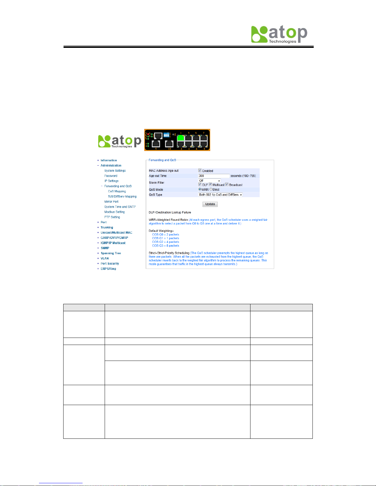
2.3.4 Forwarding and QoS
EH7510 provides:
Forwarding function
Filter functions
Quality of Service (QoS) functions
To make data delivery more reliable; for forwarding functions, users can set up an ageing
time, to avoid the case that a MAC address cannot be found, Fig. 2.10.
Filter Functions
Storm Filter Function:
For this function, users can select filtering levels,
- DLF Mode: Destination Lookup Failure. The switch will always look for a MAC
destination address first. In case that a MAC address cannot be found, which means
DLF occurs, the switch will forward the packets to all ports that are in the same VLAN.
- Multicast: This type of transmission sends messages from one host to multiple hosts.
Only those hosts that belong to a specific multicast group will receive it; also
networks that support multicast send only one copy of the information across the
network until the delivery path that reaches group members diverges. At these
diverging points, multicast packets will be copied and forwarded; this method can
manage high volume of traffic with different destinations while using network
bandwidth efficiently.
- Broadcast: Messages sent to all devices.
Atop Industrial Managed Ethernet Switch
EH7510
User Manual V 1.0
15
QoS:
The main objective of Quality of Service is to transfer certain data packets either particularly
safe or as immediately as possible. With EH7510, users are able to prioritize traffic on the
network to ensure that high priority data can be transmitted as soon as possible. Network
traffic is controlled by a set of rules. These rules help classify different types of traffic and
define how each of them should be treated as they’re being transmitted. EH7510 can also
inspect both 802.1p CoS tags and DiffServ tag to provide consistent classification.
Fig. 2.10
Table 2.5
Label
Description
Factory Default
MAC
Address
Ageing Time
Choose to enable MAC Address* ageing time
function. If enabled, when an entry reaches its aging
time, it will be cleared from the switch. Enabling this
function can cancel frame forwarding effectively.
Checked
Ageing Time
Specifies the ageing time. Range100 ~ 765 seconds.
300
Storm Filter
Select filter level from Off, 5%, 10%, 15%, 20%, or
25%.
Off
Enable storm filter function and choose from DLF,
Multicast and/or Broadcast traffic. See notes below
for a detailed description.
DLF, Multicast and
Broadcast enabled.
QoS Mode
Select the device QoS mode: WRR or Strict.
See notes below for a detailed description and
comparison.
WRR
Qos Type
802.1p CoS only: Switch only checks L2 802.1p CoS
priority bits.
Both 802.1p CoS and DiffServ: Switch checks both
types.
See notes below for a detailed description.
Both types are
selected.

Atop Industrial Managed Ethernet Switch
EH7510
User Manual V 1.0
16
QoS Mode:
- WRR: Weighted Round Robin. This method services all the traffic queues, but higher
priority queues still retain their advantage; this mode guarantees that in the event that
high-priority traffic exceeds the link capacity, lower priority traffic will still proceed and not
be blocked.
- Strict is Strict-Priority Scheduling. The QoS scheduler preempts the highest queue as long
as there are packets. When all the packets are exhausted from the highest queue, the
QoS scheduler reverts back to the weighed fair algorithm to process the remaining
queues. This mode guarantees that traffic in the highest queue always flows first.
QoS Type:
- 802.1p CoS: IEEE standard of layer 2 marking scheme. It specifies a priority value
between 0 and 7 that can be used by QoS to differentiate traffic. When this option is
enabled, EH7510 inspects the 802.1p CoS tag in the MAC frame to determine the priority
of each frame.
- DiffServ/ToS: DiffServ stands for Differentiated Services. It’s a networking architecture
that specifies a simple but scalable mechanism for classifying network traffic and
providing QoS guarantees on networks. It uses the DiffServ Code Point (DSCP, which is
the modern redefinition of the ToS). DiffServ/ToS function allows users to use up to 64
values to define service levels and set priority.
Settings of CoS and ToS can be accessed on the mapping tables in next two options.
Atop Industrial Managed Ethernet Switch
EH7510
User Manual V 1.0
17
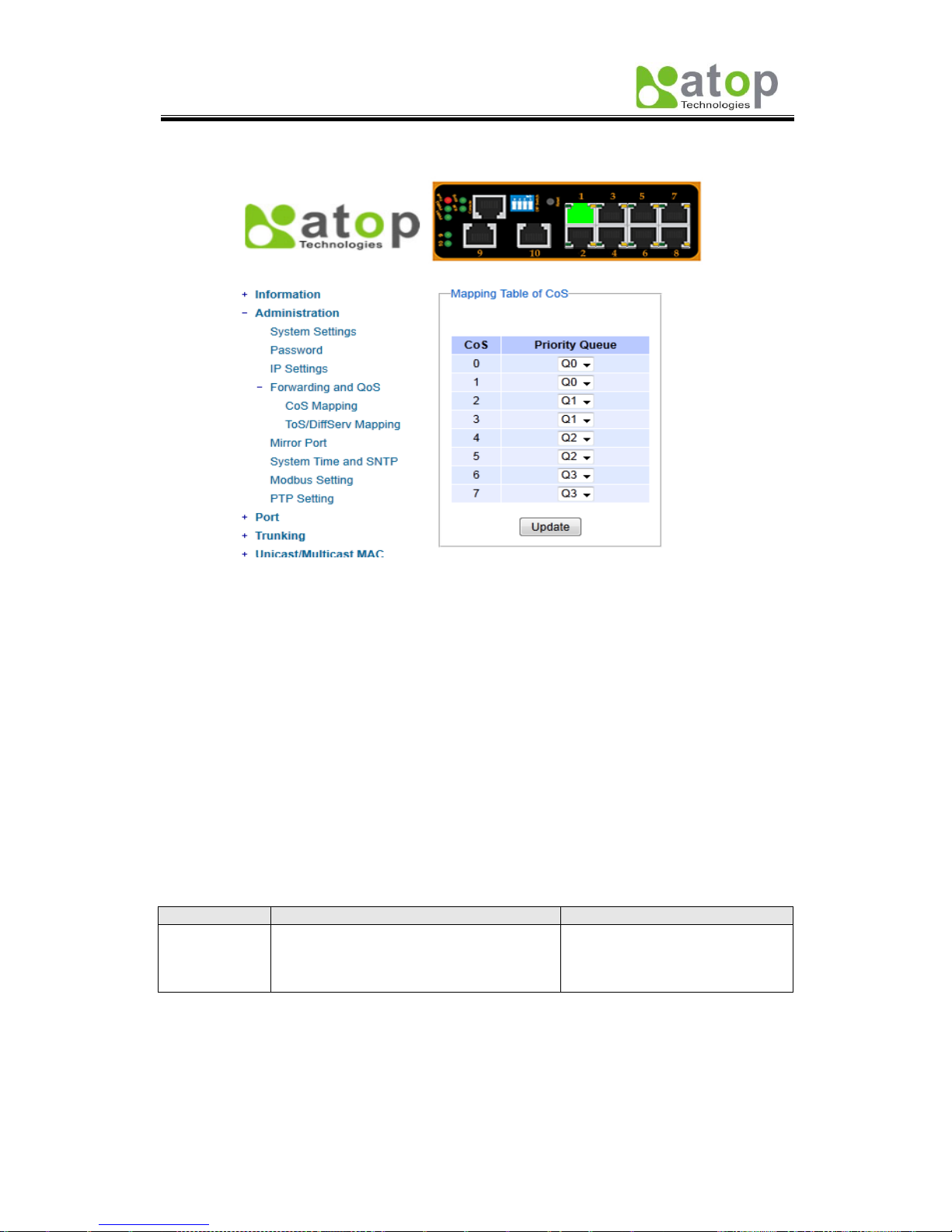
2.3.4.1 CoS Mapping
Fig. 2.11
The switch can classify traffic based on a valid 802.1p (CoS) priority tag. These options
allow users to map CoS to the different priority queues, Fig. 2.11.
The default queue weighting is assigned as follow:
Q0 = 2 packets (Lowest priority)
Q1 = 1 packets (Low priority)
Q2 = 4 packets (Median priority)
Q3 = 8 packets (High priority)
For example, Q3 has the highest priority, and it carries 8 packets, while Q0 has the lowest
priority, and it carries 2 packets. When CoS 6 is assigned to Q3, it has the highest priority.
When Co1 is assigned to Q0, it has the lowest priority. For CoS explanations, please refer
to page 14.
Table 2.6
Label
Description
Factory Default
Priority
Queue
Set the mapping table of different CoS to
4 different level queues.
CoS 0, 1: Q0
CoS 2, 3: Q1
CoS 4, 5: Q2
CoS 6, 7: Q3
Atop Industrial Managed Ethernet Switch
EH7510
User Manual V 1.0
18
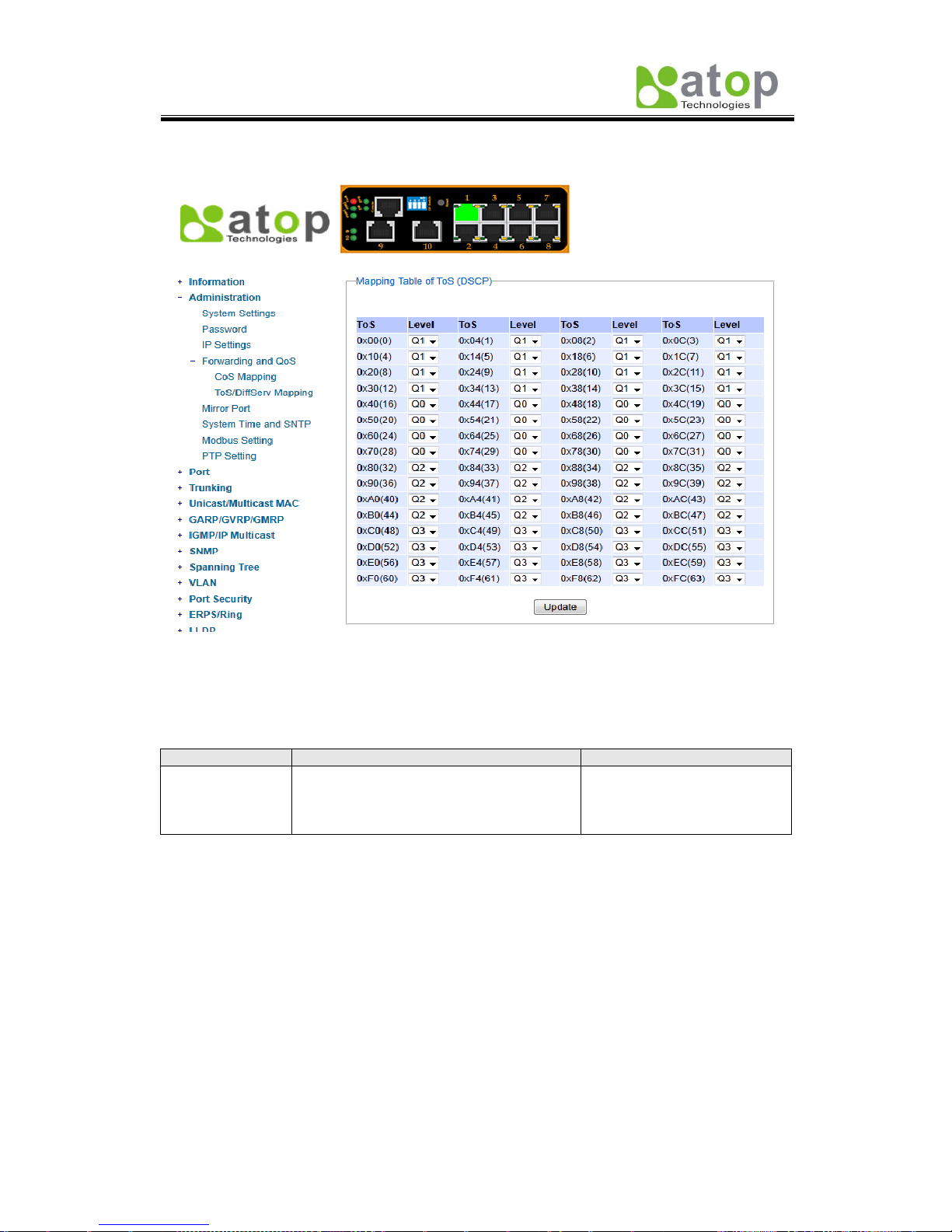
2.3.4.2 ToS/DiffServ Mapping
Fig. 2.12
The switch can classify traffic based on a valid DiffServ (ToS) priority tag; Fig. 2.12 shows
where users can map ToS to the different priority queues.
Table 2.7
Label
Description
Factory Default
Level
Sets the mapping table of different ToS to
4 distinct output queues, which are Q0
(lowest), Q1 (los), Q2 (median), and Q3
(highest).
ToS 0~15: Q1
ToS 16~31: Q0
ToS 32~47: Q2
ToS 48~63: Q3
For example, when ToS 0*F8 (62) is assigned to Q3, it has the highest priority. When ToS
0*40(16) is assigned to Q1, it has the lowest priority. For ToS explanations please refer to
page 14.
Atop Industrial Managed Ethernet Switch
EH7510
User Manual V 1.0
19
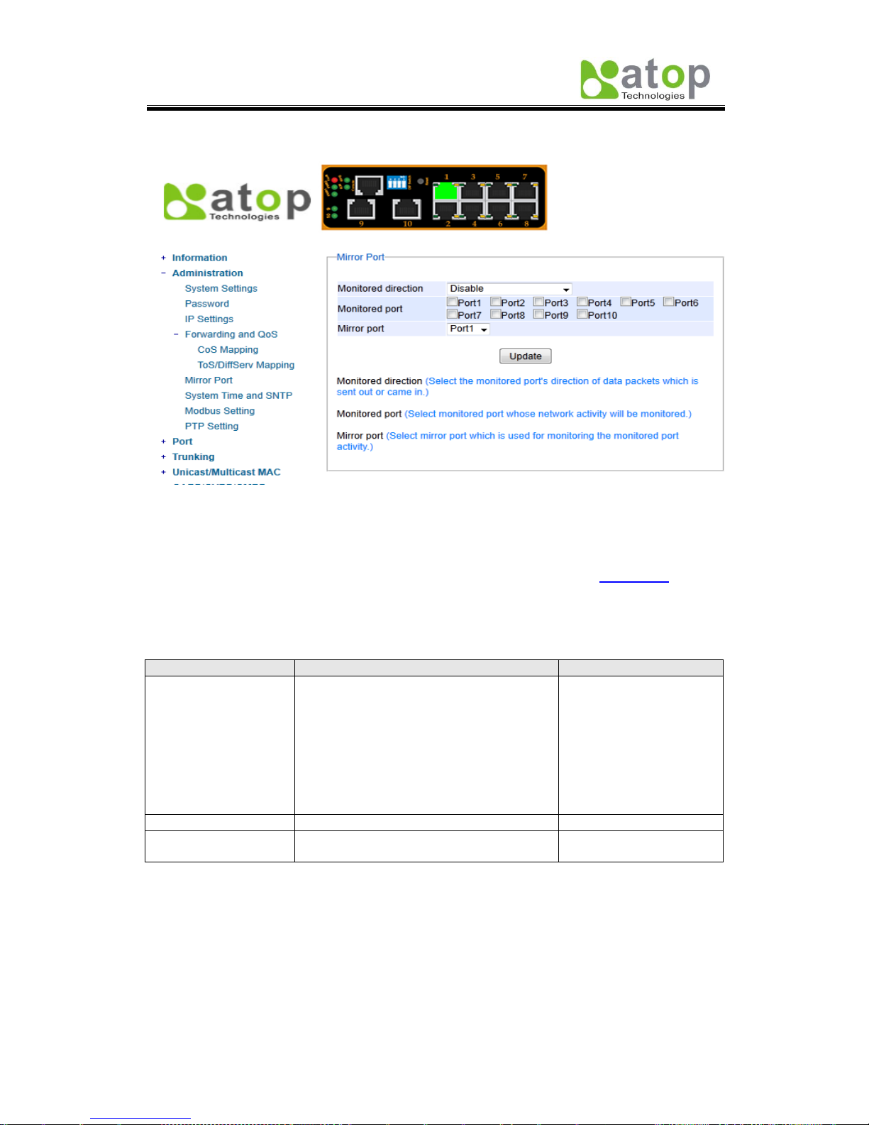
2.3.5 Mirror Port
Fig. 2.13
In order to help the network administrator keep tracks of network activities, EH7510
supports port mirroring, which allows incoming and/or exiting traffic to be monitored by a
single port that is defined as mirror port, (Fig. 2.13). IGMP snooping (Section 2.7) and
mirroring functions are mutually exclusive. When IGMP snooping is enabled, the port
mirroring function is disabled.
Table 2.8
Label
Description
Factory Default
Monitored direction
Select the monitoring direction.
Disable: disable port monitoring.
Input data stream: monitor input data
stream of monitored ports only.
Output data stream: monitor output data
stream of monitored ports only.
Input /Output data stream: monitor both
input and output data stream of monitored
ports.
Disabled
Monitored Port
Select the ports that will be monitored.
Unchecked all
Mirror port
Select the mirror port that will be used to
monitor the activity of the monitored ports.
Port1
Atop Industrial Managed Ethernet Switch
EH7510
User Manual V 1.0
20
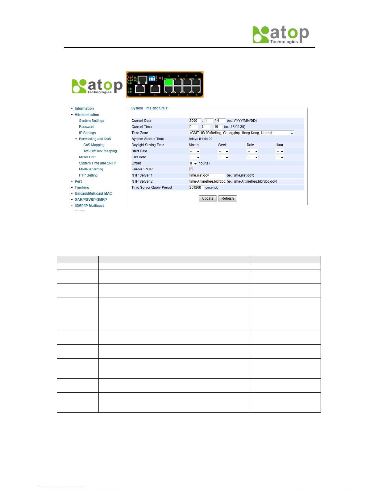
2.3.6 System Time and SNTP
Fig. 2.14
This option, (Fig. 2.14) configures EH7510 time and date; it also supports Daylight Saving
Time and SNTP (See notes below for explanation).
Table 2.9
Label
Description
Factory Default
Current Date
Allows local date configuration in yyyy/mm/dd format
None
Current
Time
Allows local time configuration in local 24-hour format.
None
System
Startup Time
Indicates how long the switch has been working.
Dependant
Daylight
Saving Time
Start Date: defines the start date of daylight saving.
End Date: defines the end date of daylight saving.
Offset: decide how many hours to be shifted
forward/backward when daylight saving time begins and
ends. See note below.
None
Enable
SNTP
Enables SNTP function. See note below.
Unchecked
NTP Server
1
Sets the first IP or Domain address of NTP Server.
time.nist.gov
NTP Server
2
Sets the second IP or Domain address of NTP Server.
Switch will locate the 2nd NTP Server if the 1st NTP
Server fails to connect.
TimeA.timefreq.bldrdoc.gov
Time Zone
User’s current local time.
(GMT+08:00)Beijing,
Chongqing, Hong Kong
Time Server
Query
Period
This parameter determines how frequently the time is
updated from the NTP server.
259200 seconds.
Note:
- Daylight Saving Time: In certain regions (e.g. US), local time is adjusted during summer
season in order to provide an extra hour of daylight in the afternoon, and the time shifted
Atop Industrial Managed Ethernet Switch
EH7510
User Manual V 1.0
21
forward (or backward) is usually an hour.
- SNTP: Network Time Protocol. It is used to synchronize the computer systems’ clocks.
Two of the NTP server examples would be time.nist.gov and clock.stdtime.gov.tw.
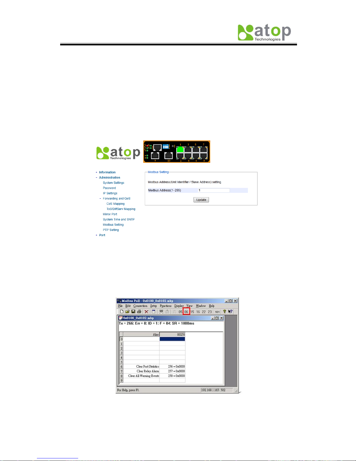
2.3.7 Modbus Setting
Modbus is a serial communication protocol which allows communication between devices to
be connected to the same network. It is used to connect a supervising computer to the
network, and thus control all the devices behind it.
Fig. 2.15
Fig. 2.15 shows where users can set up the modbus address; in addition to that, users can
use Modbus Poll for configurations. Setup steps are illustrated as follows:
1. Make sure the Modbus Poll is connected to your target EH7510.
2. Click on “06” on the top toolbar.
Fig. 2.16
Atop Industrial Managed Ethernet Switch
EH7510
User Manual V 1.0
22
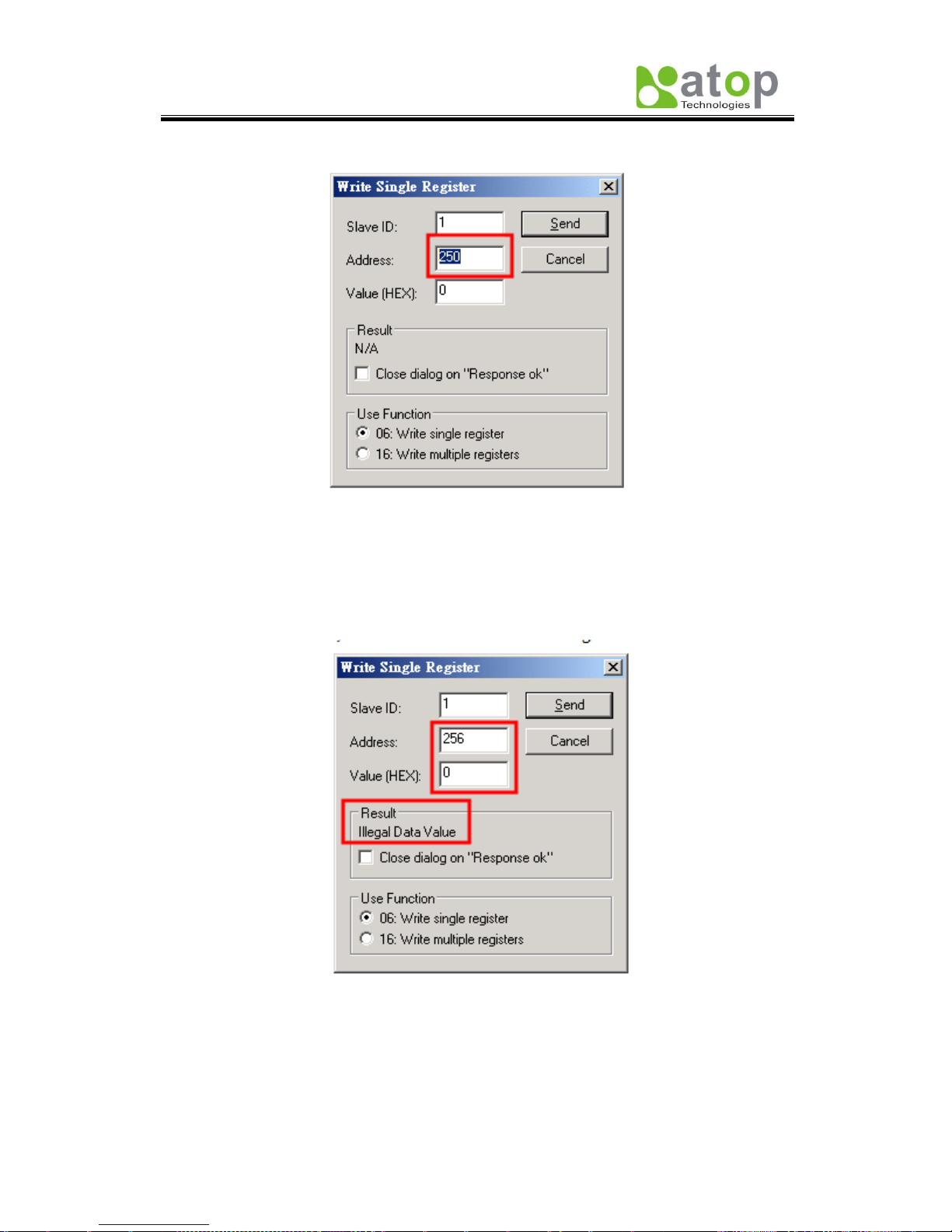
3. Set Address to a desired value between 250 and 256.
Fig. 2.17
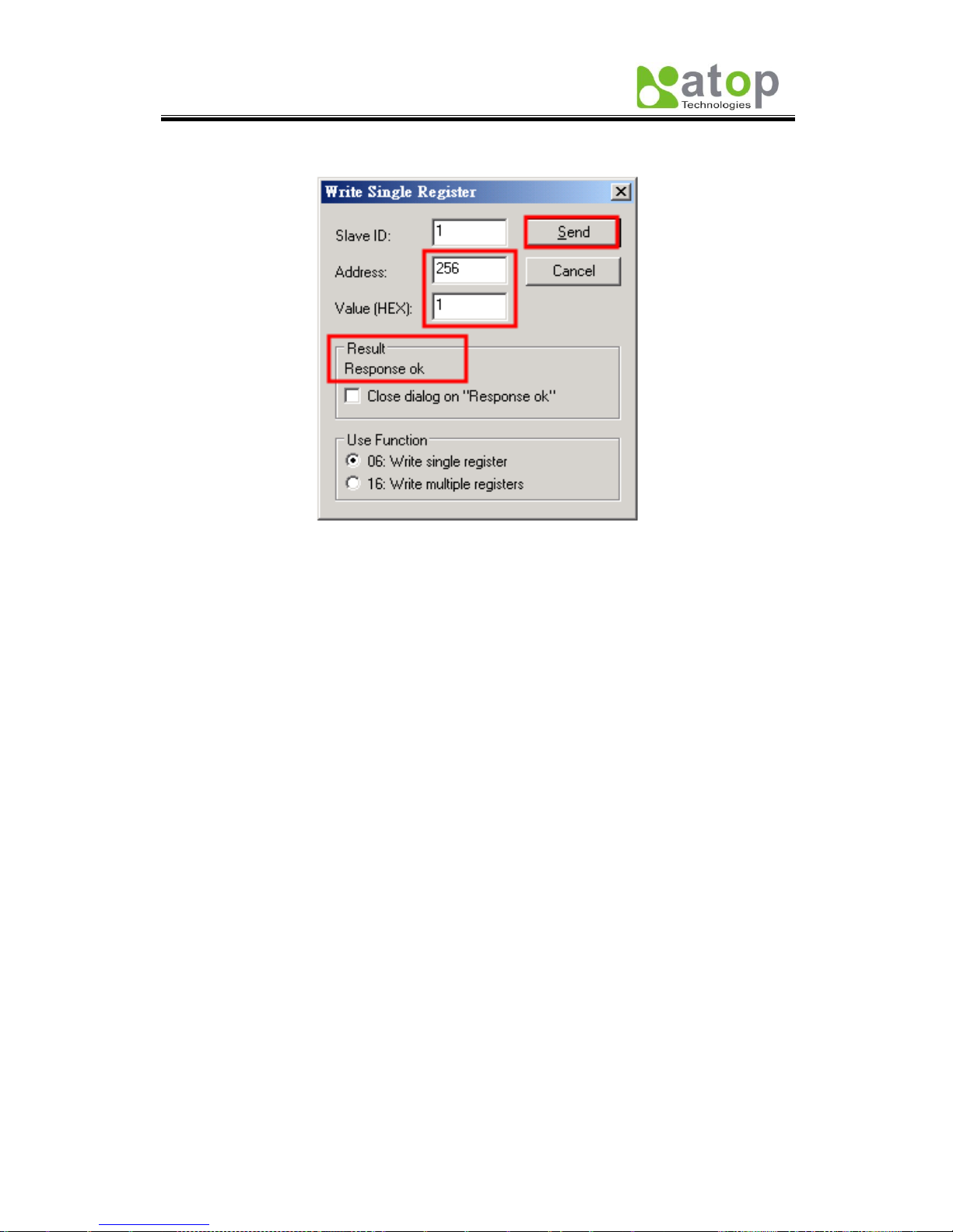
4. Correct Value (HEX) has to be selected corresponding to Address entered above. As in
this example, Result shows “Illegal Data Value” since Address 256 can only take 1 as
Value (HEX).
Fig. 2.18
Atop Industrial Managed Ethernet Switch
EH7510
User Manual V 1.0
23
5. If a correct Value (HEX) is selected, the process will be completed successfully.
Fig. 2.19
Atop Industrial Managed Ethernet Switch
EH7510
User Manual V 1.0
24
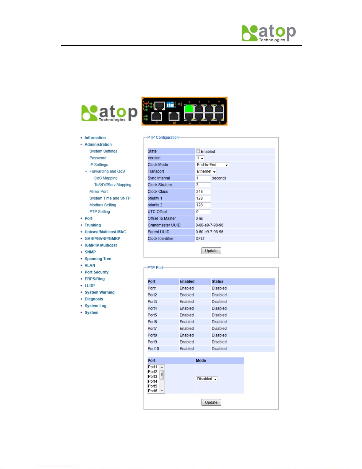
2.3.8 PTP Setting
The Precision Time Protocol (PTP) is a high-precision time protocol. It is for precise
synchronization of clocks on a local area network by measurement and control systems. Fig.
2.20 (on the next page), shows where to configure PTP and to see PTP status
.
Fig. 2.20
 Loading...