

Euromatic AGC 800/22, AGC 800/60, AGC 1100/60 Operating Instructions Manual
• Hauswasserwerk
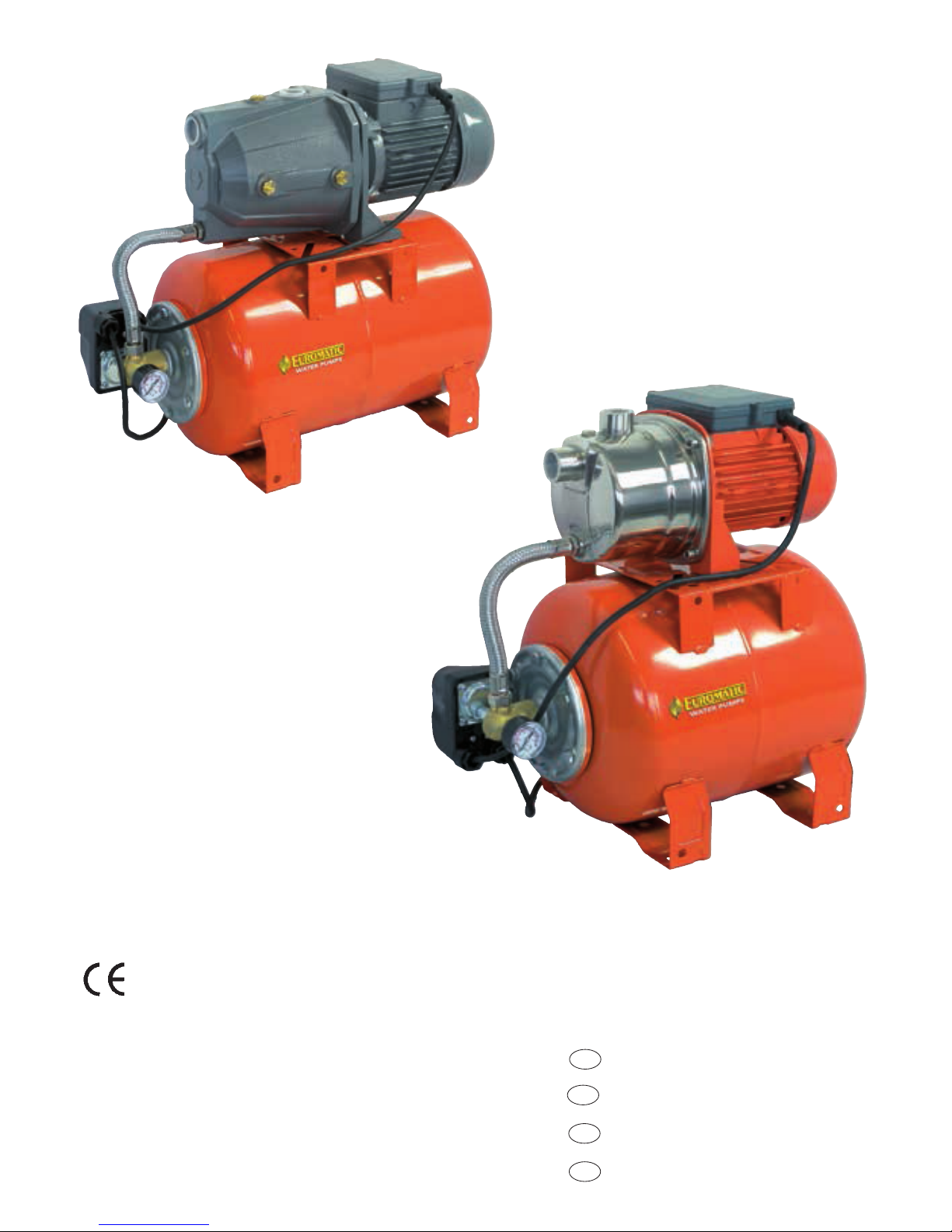
• Pump with pressure tank
• Pompe avec réservoir de pression
• Autoclave
• Autoclaaf
• Autoclave
• Autoclave
• Husvandværk
• Pump med trycktank
• Vesiautomaatti
• Stigepumpe
•
Πιεστικ µηάνηµα άντλησησ
• Hidrofor
•
Pompa ze zbiornikiem ciśnienia
• Autokláv
• Házi vizellátó rendszer
• ABTOКЛAB
•
• Hidroforas
• Veeautomaat
• Hidropak
• Hidrofoare
• Hidropak
• Hauswasserwerk
• Pump with pressure tank
• Pompe avec réservoir de pression
• Autoclave
• Autoclaaf
• Autoclave
• Autoclave
• Husvandværk
• Pump med trycktank
• Vesiautomaatti
• Stigepumpe
•
Πιεστικ µηάνηµα άντλησησ
• Hidrofor
•
Pompa ze zbiornikiem ciśnienia
• Autokláv
• Házi vizellátó rendszer
• ABTOКЛAB
•
• Hidroforas
• Veeautomaat
• Hidropak
• Hidrofoare
• Hidropak
• Pump with pressure tank
• Autoclave
• Domácí vodárna
Operating instructions
Libretto istruzioni
Návod k obsluze
CZ
Návod na obsluhu
SK
GB
I
• Domáca vodáreň

AGC
800/22
AGC
800/60
AGC
1100/60
230 V ~
50 Hz
230 V ~
50 Hz
230 V ~
50 Hz
800 W 800 W 1100 W
3,8 A 3,8 A 5,0 A
10 A 10 A 10 A
F F F
IP 44 IP 44 IP 44
12,5 μF 12,5 μF 20 μF
40 m 40 m 48 m
60
L/min
60
L/min
70
L/min
8 m 8 m 9 m
35°C 35°C 35°C
1” 1” 1”
17,7 Kg.
L=490 mm
B=280 mm
H=480 mm
1,4 bar
2,8 bar
1,4 bar
2,8 bar
1,6 bar
3,2 bar
23,8 Kg.
L=770 mm
B=400 mm
H=700 mm
L=770 mm
B=400 mm
H=700 mm
• Supply voltage • Tensione nominale • napêti v síti • siet’ové napätie
Technical data - Dati tecnici - Technnická data - technické údaje
• Power consumption • Potenza assorbita • Přikon • Príkon
• Current input • Corrente nominale • Proud • Menovitý prúd
• Required fuse • Fusibile necessario • Doporučené jištění zasuvky • Odporúčané
istenie zasuvky
• Insulation class • Classe d’isolamento • Izolačni třída • Izolačná trieda
• Protective device • Protezione • Druh krytí • druh krytia
•
Capacitor capacity • Capacità del condensatore • Kapacita kondenzátoru
• Kapacita kondenzátora
•
Maximum head height • Prevalenza max. • Maximálni výtlak
• Maximálny výtlak
•
Maximum delivery
•
Portata max.
•
Maximálni dodávané množství
• Maximálne dodávané mnoźstvo
•
Max. suction height
•
Massima profondità d’aspirazione
•
Max. sací výška
• Max.sacia výška
•
Max. Water temperature • Temperatura. max.
• Max. teplota vody • Maximálna teplota
•
Pressure pipe min. • Diametro min. tubo mandata
•
Min. dimenze výtlaku
• Minimalny priemer výtlačného potrubia
• Weight • Peso • Hmotnost • Hmotnost’
• Packing dimensions • Dimensioni imballo • Rozměry balení
• Rozmery balenia
•
Adjusted switch on/off pressure • Pressostato pre-tarato • Zapínací/vypínací tlak
• Z
apínací/vypínací tlak
230 V 230 V 230 V
8 m
25,6 Kg.
1. Safety Measures
• Read carefully the operating instruction before assembling
and starting.
The appliance must not be used by operators who are
not thoroughly acquainted with the instructions handbook
(operating instructions). Moreover, the appliance must
not be used by persons under the age of 16.
• The user is liable towards third parties in the area where
the appliance is in operation.
• Before starting it is necessary to make sure that there
are the necessary electrical protection measures, by
means of a test carried out by a specialist.
While the pump is operating persons must
not be in the liquid to be pumped.
The pump may be connected only by
means of a safety switch for fault currents, with
a rated opening current up to 30 mA and a socket
with an earth contact installed in compliance with
the regulations. Protection: at least 10 Amps.
Operation in swimming pools and garden ponds is
not recommended.
For other operation, the provisions in conformity with
the standard VDE 0100 part 702 must be respected.
CAUTION: Before checking, connect the pump and
the system with no voltage!
Replacing the connecting up line requires using special
tools and therefore this must carried out by the
manufacturer or its service engineers.
The pump may only operate with a pipe connecting
the appliance (extension) that is no lighter than a
rubber hose mod. H07 RNF in compliance with the
DIN 57282 or DIN 57245 standard.
• The noise (continuous equivalent in dbA) of
the motor-driven pump is less or equal (≤) to 70
dbA.
• The voltage (230 Volts alternating current) indicated on
the pump’ s rating plate must correspond to the available
mains voltage.
• The temperature of the liquid conveyed must not exceed
35°C.
• Make sure that the plugged electrical connections are
in an area safe from flooding and are protected from
humidity.
• Before use it is necessary to check that the plug and
the mains connection line are not damaged.
• Unplug from the mains before performing any work on
the pump.
• Avoid directly exposing the pump to the jet of water.
• The user is responsible for complying with the local
regulations for assembly and safety.
• The user by taking appropriate measures (e.g. installing
an alarm, reserve pump and the like) will have to exclude
PUMP WITH PRESSURE TANK
the possibility of indirect damage caused by flooding
premises due to failure of the pump.
• In the event of the pump failing, repair work may only
be carried out by the repair workshops of the technical
service. Only genuine spare parts must be used.
• It is notified that in conformity with the law on product
liability
we cannot be held responsible
for the damage caused by our appliance:
a) because of improper repairs not carried out by the
personnel of the assistance points authorized by us; or
b) if GENUINE SPARE PARTS are not used to replace
parts; or
c) if the indications and provisions given in the instructions
handbook are not complied with.
The same provisions hold for the accessories.
2. Use
CAUTION! Sector of use
The pressure tanks units are used to supply water to
houses, farms and factories when the water may be
drawn from a well or from a spring and, in addition,
for irrigation in market gardening or agriculture. To
raise the pressure of the water mains in accordance
with local regulations (max. pressure on inlet 2 bar).
Operating Instructions
Generally speaking it is recommended to use a
preliminary filter and exhauster with a suction
hose, suction rose and foot valve (reflux lock) to
avoid long suction times and pointlessly
damaging the pump due to stones and solid
foreign bodies.
3. Before Starting
The pressure tank unit is self-sucking. Before starting for
the first time the pump has to be filled through the delivery
union with the delivery liquid until it overflows.
Suction Piping
• Fit the suction pipe for drawing water rising towards the
pump. Absolutely avoid fitting the suction pipe higher than
the pump (formation of air bubbles in the suction pipe).
• The suction and delivery piping must be fitted so as not
to be able to apply any mechanical pressure on the pump.
• The suction valve should be situated at least 30 cm.
below the bottom water level.
• Suction pipes that are not airtight suck in air obstructing
suction of the water.
Delivery Piping
During suction, the cut-off parts (sprayers, valves, etc.)
situated in the delivery piping have to be fully open so
that the air in the suction pipe can be freely expelled.
�
4. Maintenance Instructions
The pressure tank unit is entirely maintenance-free.
If the pump gets blocked it will first have to be rinsed out.
Connect the pump after removing delivery pipe to the
water pipe and let water flow into the suction pipe.
While water is flowing into the pump, engage it several
times for about 2 seconds.
In this way it is possible to eliminate most blockages.
• If there is a risk of frost, the pump has to be emptied
completely.
• When the pump is not going to be used for a long time,
for instance in the winter period, it is recommended to
rinse out the pump thoroughly with water, empty it
completely and store it in a dry place.
• Check whether the pump works freely by briefly
connecting and disconnecting it.
• Then fill the pump again with the delivery liquid and set
it up for use.
Adjusting connection and cut-off pressure.
The pressure tanks unit are factory set with an operating
pressure of 1,4÷2,8 or 1,6÷3,2 bar (see table of
specifications). The connection and cut-off pressure can
be adjusted and may be set the desired pressure onto
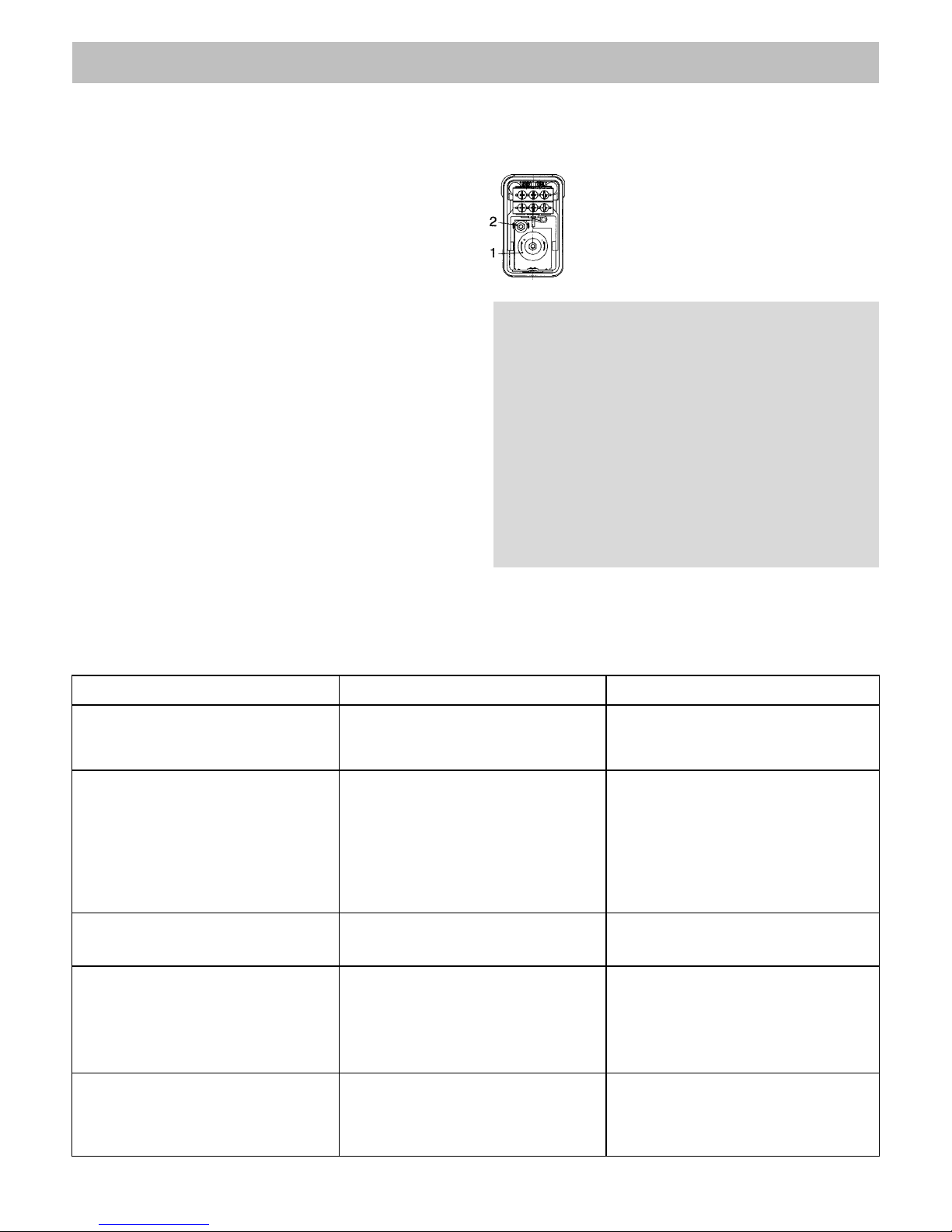
according to your need by means of the switch (see
figure).
1 = Connection pressure
2 = Cut-off pressure
Take the protective cover off the pressure
switch. With a screwdriver, turn onto - or +
according to need. Check the pressure with
the pressure gauge.
CAUTION!
In order to work, the pump must always be filled
with the delivery liquid until it overflows!
Caution: The pump must never run dry. The
manufacturer’s warranty is null and void in the
event of damage to the pump caused by its running
dry.
Check that the pump is airtight; piping that is not
airtight draws in air preventing the pump from
working properly.
If it is not possibile to eliminate the trouble, please call our service department.
To avoid damage during transport, please ship in the ORIGINAL PACKING.
15
5. Troubleshooting Table
Trouble Cause Remedy
Motor will not start
Pump will not suck
Insufficient rate of flow
The thermal cut-out switch cuts
off the pump
• No mains voltage.
• Pump impeller jammed.
Thermostat detached.
• Check voltage.
• Dismantle the pump and clean it.
• Suction valve not in water.
• Pump chamber with no water.
• Air in suction pipe.
• Suction valve not airtight.
• Suction rose (suction valve) clogged.
• Max. suction height exceeded.
• Put the suction valve into water
(min. 30 cm.)
• Pour water into the suction union.
• Check the seal of the suct. pipe.
• Clean the suction valve.
• Clean the suction rose.
• Check the suction height.
• Suction height too high.
• Dirty suction rose.
• Water level falls quickly.
• Pump flow rate reduced by foreign
bodies.
• Check suction height.
• Clean the suction rose.
• Set the suct. valve lower down.
• Clean the pump and replace the worn
parts.
• Motor overloaded.
Friction too great due to foreign bodies.
• Eliminate the foreign bodies.
Wait for the thermal cut-out switch to
trigger again (approx. 20 mins.).
Pump connects with very low
water intake
• Pressure of air cushion in the delivery
tank too low.
• Increase the pressure of the air cushion
in the filling valve (1.5 bar)
�
4. Maintenance Instructions
The pressure tank unit is entirely maintenance-free.
If the pump gets blocked it will first have to be rinsed out.
Connect the pump after removing delivery pipe to the
water pipe and let water flow into the suction pipe.
While water is flowing into the pump, engage it several
times for about 2 seconds.
In this way it is possible to eliminate most blockages.
• If there is a risk of frost, the pump has to be emptied
completely.
• When the pump is not going to be used for a long time,
for instance in the winter period, it is recommended to
rinse out the pump thoroughly with water, empty it
completely and store it in a dry place.
• Check whether the pump works freely by briefly
connecting and disconnecting it.
• Then fill the pump again with the delivery liquid and set
it up for use.
Adjusting connection and cut-off pressure.
The pressure tanks unit are factory set with an operating
pressure of 1,4÷2,8 or 1,6÷3,2 bar (see table of
specifications). The connection and cut-off pressure can
be adjusted and may be set the desired pressure onto
according to your need by means of the switch (see
figure).
1 = Connection pressure
2 = Cut-off pressure
Take the protective cover off the pressure
switch. With a screwdriver, turn onto - or +
according to need. Check the pressure with
the pressure gauge.
CAUTION!
In order to work, the pump must always be filled
with the delivery liquid until it overflows!
Caution: The pump must never run dry. The
manufacturer’s warranty is null and void in the
event of damage to the pump caused by its running
dry.
Check that the pump is airtight; piping that is not
airtight draws in air preventing the pump from
working properly.
If it is not possibile to eliminate the trouble, please call our service department.
5. Troubleshooting Table
Trouble Cause Remedy
Motor will not start
Pump will not suck
Insufficient rate of flow
The thermal cut-out switch cuts
off the pump
• No mains voltage.
• Pump impeller jammed.
Thermostat detached.
• Check voltage.
• Dismantle the pump and clean it.
• Suction valve not in water.
• Pump chamber with no water.
• Air in suction pipe.
• Suction valve not airtight.
• Suction rose (suction valve) clogged.
• Max. suction height exceeded.
• Put the suction valve into water
(min. 30 cm.)
• Pour water into the suction union.
• Check the seal of the suct. pipe.
• Clean the suction valve.
• Clean the suction rose.
• Check the suction height.
• Suction height too high.
• Dirty suction rose.
• Water level falls quickly.
• Pump flow rate reduced by foreign
bodies.
• Check suction height.
• Clean the suction rose.
• Set the suct. valve lower down.
• Clean the pump and replace the worn
parts.
• Motor overloaded.
Friction too great due to foreign bodies.
• Eliminate the foreign bodies.
Wait for the thermal cut-out switch to
trigger again (approx. 20 mins.).
Pump connects with very low
water intake
• Pressure of air cushion in the delivery
tank too low.
• Increase the pressure of the air cushion
in the filling valve (1.5 bar)
1. Misure di sicurezza
• Leggere attentamente le istruzioni per l’uso prima di effettuare
il montaggio e la messa in funzione. È vietato l’uso dell’apparecchio alle persone che non conoscono in modo approfondito
il libretto d’istruzioni (istruzioni per l’uso). L’uso dell’apparecchio
è inoltre vietato ai minori di 16 anni.
• L’utente è responsabile nei confronti di terzi nella zona in
cui l’apparecchio è in funzione.
• Prima della messa in funzione occorre assicurarsi che ci
siano le necessarie misure elettriche di protezione, mediante
una prova eseguita da uno specialista.
DURANTE l’uso della pompa non devono
esserci persone in acqua o nel liquido da
pompare, ed è proibito eseguire qualsiasi
tipo di manutenzione.
La pompa deve essere collegata solo per mezzo di
un interruttore di sicurezza salvavita, con una corrente
nominale di apertura fino a 30 mA e una presa con
contatto di terra installata conformemente alle disposizioni. Protezione: minimo 10 Amp.
Non è previsto l’utilizzo in piscine e stagni da giardino.
Per altri usi, devono essere rispettate le prescrizioni
conformi alla Norma VDE 0100 parte 702.
ATTENZIONE: Prima di effettuare il controllo della
pompa disinserire la spina.
Per la sostituzione del cavo di alimentazione serve un
attrezzatura speciale quindi dovete rivolgervi al centro
assistenza autorizzato.
La pompa può funzionare con una prolunga che sia
realizzata con cavo mod. H07 RNF conforme alle norme
vigenti e di una sezione di filo non inferiore ad 1 mm.
conforme alla norma DIN 57282 oppure DIN 57245.
• La rumorosità (continua equivalente in dbA) delle
elettropompe è inferiore o uguale (≤) a 70 dbA.
• La tensione (230 Volt corrente alternata) indicata
sulla targhetta della pompa deve corrispondere alla tensione
di rete disponibile.
• La temperatura del liquido convogliato non deve superare
35°C max.
• Assicurarsi che le connessioni elettriche a spina si trovino
in una zona sicura da allagamenti e siano protette dall’umidità.
• Prima dell’uso occorre verificare che la linea di allacciamento
alla rete e la spina non siano danneggiate.
• Disinserire la spina della rete prima di compiere qualsiasi
intervento nella pompa.
• Evitare che la pompa sia esposta direttamente al getto d’acqua.
• L’utente è responsabile del rispetto delle locali disposizioni
di montaggio e sicurezza.
• L’utente dovrà escludere mediante provvedimenti adeguati
(per es. installazione di allarme, pompa di riserva e simili) la
possibilità di danni indiretti causati dall’allagamento di locali
per guasti della pompa.
• In caso di eventuale guasto della pompa, i lavori di riparazione
AUTOCLAVE
pot
ranno essere effettuati solo dalle officine di riparazione
del servizio assistenza. Devono essere usati solo pezzi di
ricambio originali.
• Si avverte che ai sensi della legge sulla responsabilità del
prodotto
non rispondiamo
dei danni che vengono causati dal nostro apparecchio:
a) per riparazioni improprie che non vengono effettuate dal
personale dei punti di assistenza da noi autorizzati;
b) oppure se per una sostituzione di pezzi non vengono
utilizzati PEZZI DI RICAMBIO ORIGINALI;
c) oppure se non vengono rispettate le indicazioni e le
disposizioni riportate nel libretto d’istruzioni.
Per gli accessori valgono le stesse disposizioni.
2. Impiego previsto
ATTENZIONE! Settore d’impiego
L’autoclave serve per fornire l’acqua nelle case monofamiliari, nelle aziende agricole e negli stabilimenti industriali
quando l’acqua può essere prelevata da un pozzo o da
una sorgente ed inoltre per l’irrigazione in agricoltura.
Per elevare la pressione della rete idrica secondo le
disposizioni locali (max. pressione all’entrata 2 bar).
Istruzioni per l’uso
Principalmente si consiglia l’uso di un filtro preliminare
adeguato e di un kit d’aspirazione dotato di un tubo
flessibile con valvola di fondo (arresto di riflusso) per
evitare lunghi tempi di risucchio e un inutile danneggiamento della pompa dovuti a pietre e corpi estranei
solidi.
3. Prima della messa in funzione
Il Vostro autoclave per l’irrigazione è autoadescante. Precedentemente alla prima messa in funzione la pompa deve
essere riempita attraverso il raccordo di mandata con il liquido
di mandata, fino alla fuoriuscita dello stesso.
Tubazione aspirante
• Montare il tubo aspirante del prelievo acqua ascendente
verso la pompa. Evitare assolutamente di montare il tubo
aspirante oltre l’altezza della pompa (formazione di bolle
d’aria nel tubo aspirante).
• La tubazione aspirante e di mandata deve essere montata
in modo tale da non poter esercitare alcuna pressione meccanica sulla pompa.
• La valvola aspirante dovrebbe essere situata almeno 30
cm. sotto il livello d’acqua inferiore.
• Le tubazioni aspiranti non ermetiche aspirano aria ostacolando l’aspirazione dell’acqua.
Tubazione di mandata
Durante la fase di aspirazione gli organi di arresto (spruzzatori,
valvole ecc.) situati nella tubazione di mandata devono essere
completamente aperti, affinché l’aria presente nel tubo aspirante possa essere espulsa liberamente.
�
4. Istruzioni per la manutenzione
L’autoclave per irrigazione necessita di scarsa manutenzione.
Se la pompa si intasa si deve effettuare innanzitutto un
risciacquo della stessa. Se si dovesse verificare un intasamento
è dovuto all’inefficenza dei filtri o/e la sua totale mancanza
quindi per il ripristino smontare la parte idraulica risciacquare
tutto l’interno rimontare accuratamente ripristinare i filtri in
modo corretto ed effettuare la messa in funzione.
• In caso di pericolo di gelo la pompa deve essere svuotata
completamente
• Prima di un lungo periodo di inutilizzo della pompa, (per es.
nel periodo invernale), si consiglia di risciacquare a fondo la
pompa con acqua, svuotarla completamente e riporla in luogo
asciutto.
• Prima della rimessa in funzione controllare se la pompa
funziona liberamente, accendendo e spegnendo brevemente
la stessa.
• Riempire poi nuovamente la pompa con liquido di mandata
e predisporla per l’uso.
Regolazione della pressione di inserzione e di interruzione
L’autoclave viene impostato in produzione su una pressione
d’esercizio di 1,4÷2,8 o 1,6÷3,2 bar (vedi tabella dati tecnici).
La pressione d’inserzione e d’interruzione è regolabile e può
essere impostata sulla pressione desiderata mediante l’inter-
ruttore, a seconda delle diverse esigenze (Vedi figura).
1 = Pressione d’inserzione
2 = Pressione d’interruzione
Disinserire la spina, togliere il coperchio di
protezione del pressostato. Con un cacciavite
girare su - o +, a seconda delle esigenze.
Controlli della pressione attraverso il manometro.
ATTENZIONE!
La pompa per poter aspirare deve essere sempre
riempita con il liquido di mandata fino alla fuoriuscita
dello stesso!
Attenzione: la pompa non deve mai funzionare a
secco, l’inadempienza di tale regola fà decadere
immediatamente la garanzia totale della pompa.
Controllare l’ermeticità della pompa; le tubazioni non
ermetiche aspirando aria impediscono il perfetto
funzionamento della pompa.
Qualora non sia possibile eliminare il guasto, siete pregati di rivolgervi al nostro servizio assistenza.
Per evitare danni durante il trasporto si prega effettuare la spedizione nell’IMBALLAGGIO ORIGINALE.
19
5. Tabella per la determinazione dei guasti
Guasti Cause Rimedi
Il motore non parte
La pompa non aspira
Portata insufficiente
L’interruttore termico disinserisce
la pompa
• Manca la tensione di rete
• Girante pompa bloccata
• Termostato staccato
• Verificare la tensione
• Smontare la parte idraulica e controllare
se la girante è libera di ruotare, rimontare
con cura
• Valvola aspirante non nell’acqua
• Camera pompa senza acqua
• Aria nel tubo aspirante
• Valv. aspir. non ermetica
• Filtro aspirazione sporco
• Superata la max. altezza di aspirazione
• Mettere in acqua la valvola aspirante
(min. 30 cm.)
• Versare acqua nel raccordo aspir.
• Verificare la tenuta del tubo aspir.
• Pulire la valvola aspirante
• Pulire il filtro
• Controllare l’altezza di aspirazione
• Altezza di aspirazione troppo elevata
• Filtro aspirazione sporco
• Il livello dell’acqua si abbassa
rapidamente
• Portata della pompa ridotta da corpi
estranei
• Verificare l’altezza di aspirazione
• Pulire il filtro
• Disporre più in basso la valvola
aspirante
• Pulire la pompa e sostituire i pezzi
usurati
• Motore sovraccarico.
Attrito troppo forte dovuto a corpi
estranei
• Eliminare i corpi estranei.
Aspettarefinché l’interruttore termico
di protezione non scatti nuovamente
(ca. 20 min.)
La pompa si inserisce con una
bassissima uscita di acqua
• Pressione troppo bassa del cuscino
d’aria nel serbatoio di mandata
• Aumentare la pressione del cuscino d’aria
tramite valvola di riempimento (1,5 bar)
 Loading...