

Page 1

MODEL
CUF54
TCUF54
540mm
Ceramic Upright
Manual
Installation and Operation
Page 2

3
2
Controlling the heating zones of the ceramic hob
Electronic programmer
18
20
21
27
Page 3
5
4
l
l
l
l
The appliance becomes hot during operation. Take care not to touch the hot parts
inside the oven.
l
Always keep children away from the cooker.
While in operation direct contact with
l
Ensure that small items of household equipment, including connection leads, do not
touch the hot oven or the hob as the insulation material of this equipment is usually
not resistant to high temperatures.
l
Do not leave the cooker unattended when frying. Oils and fats may catch fire due to
overheating.
l
Do not allow the cooktop to get soiled and prevent liquids from boiling over onto the
surface of the cooktop, Any spillages should be cleaned up as they happen.
l
Do not place pans with a wet bottom on the warmed up heating zones as this can
cause irreversible changes to the cooktop(irremovable stains).
l
Do not switch on the cooktop until a pan has been placed on it.
l
Do not put pans weighing over 15kg on the opened door of the oven and pans over
25kg on the cooktop.
l
Do not use harsh cleaning agents or sharp metal objects to clean the doors as they
can scratch the surface, which could then result in the glass cracking.
l
Do not use the cooker in the event of a technical fault. Any faults must be fixed by an
appropriately qualified and authorized person.
l
In the event of any incident caused by a technical fault, disconnect the power and
report the fault to the service centre to be repaired.
l
The rules and provisions contained in this instruction manual should be strictly
observed. Do not allow anybody who is not familiar with the contents of this instruction
manual to operate the cooker.
l
The cooker should not be cleaned using steam equipment.
WARNING:Accessible parts may become hot during use.Young children should be
kept away.
WARNING:Accessible parts will become hot when the grill is in use .Children should be
kept away.
The appliance is not intended to be operated by means of an external timer or separate
remote-control system.
This appliance is not intended for use by persons (including children) with reduced
Children should be supervised to ensure that they do not play with the appliance.
physical, sensory or mental capabilities, or lack of experience and knowledge,unless
they have been given supervision or instruction concerning use of the appliance by a
person responsible for their safety.
If the supply cord is damaged, it must be replaced by the manufacturer or its service
agent or a similarly qualified person in order to avoid a hazard.
WARNING:In order to prevent accidental tipping of the appliance ,for example by a
child climbing onto the open door,the stabilizing means must be installed.
The oven must be switched off before removing the guard and that,after cleaning,the
guard must be replaced in accordance with the instrctions.
Ensure that the appliance is switched off before replacing the lamp to avoid the
possibility of electric shock.
the cooker may cause burns!
Use pans that are specified by the manufactruer as designed for use with a ceramic hob.
If the surface is cracked,switch off the appliance to avoid the possibility of electric shock.
If the appliance used in New Zealand,this
cooking range must be connected to the
supply by a supply cord fitted with an
appropriately rated plug that is compatible
with the socket-outlet fitted to the final
sub-circuit in the fixed wiring that is
intended to supply this cooking range.
Do not use pans with sharp edges that may
cause damage to the ceramic hob.
Do not look directly at the halogen heating
zone (not covered with a pan)when they
are warming up.
Page 4
temperature
7
6
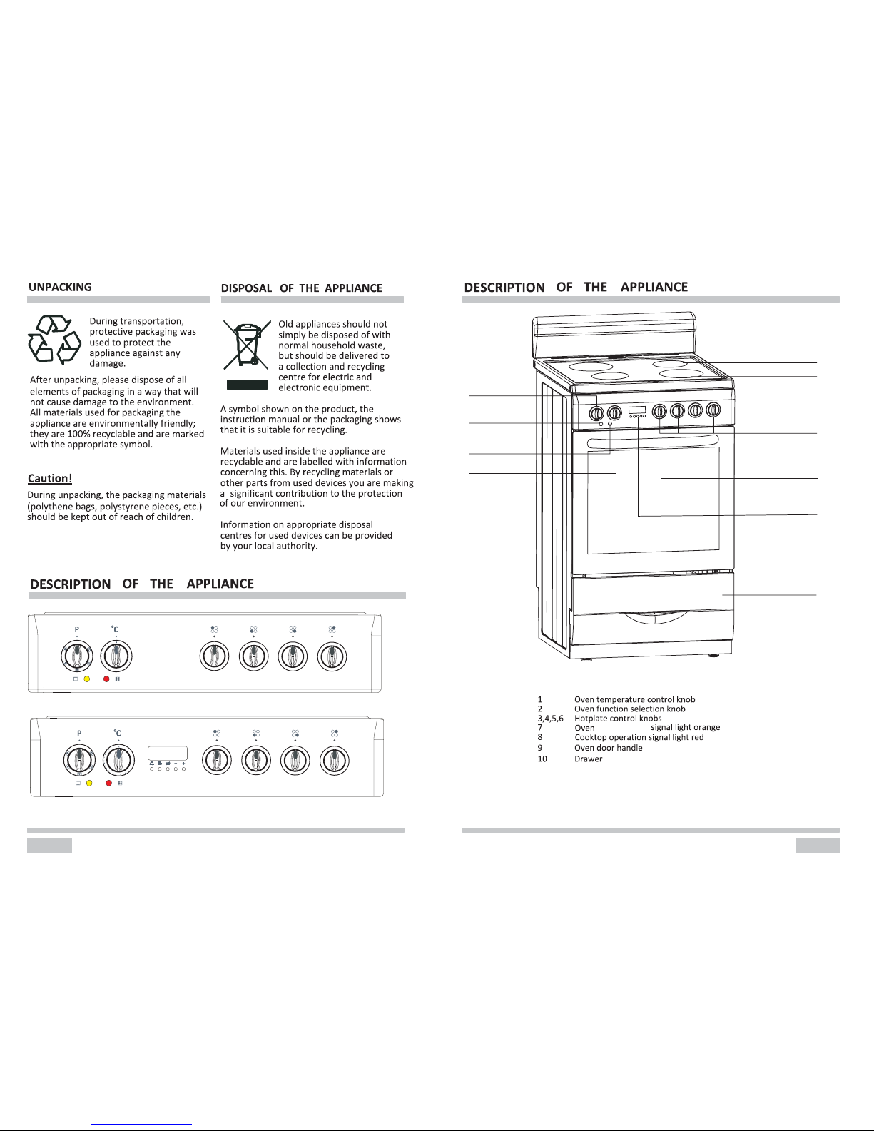
1
3,4,5,6
11
12
9
13
10
7
2
8
11 180mm Hi-light heater
12 145mm Hi-light heater
13 Electronic programmer(only for TCUF54)
5
0
10
0
1
50
200
2
5
0
0
0
9
8
7
6
4
5
1
2
3
0
9
8
7
6
4
5
1
2
3
0
9
8
7
6
4
5
1
2
3
0
9
8
7
6
4
5
1
2
3
5
0
10
0
1
50
2
00
2
5
0
0
0
9
8
7
6
4
5
1
2
3
0
9
8
7
6
4
5
1
2
3
0
9
8
7
6
4
5
1
2
3
0
9
8
7
6
4
5
1
2
3
CUF54 Control panel
TCUF54 Control panel
Page 5
INSTALLATION
Installing the cooker
The room should be equipped with a
ventilation system that pipes away
exhaust fumes created during combustion. This system should consist of
a ventilation grid or hood. Hoods should
be installed according to the manufac-
turer’s The cooker shouldinstructions.
be placed so as to ensure free access
to all elements.control
Coating or veneer used on
fitted
furniture must be applied with a heat
resistant adhesive (100 ). This
prevents surface deformation or
detachment of the coating. If you are
unsure of your furniture’s
heat
resistance, you should leave
approximately 2 cm of free space
around the cooker. The wall behind
the cooker should be resista
nt to high
temperatures. During operation, its
back side can warm up to around
50 above the ambient temperature.
The cooker should stand on a hard,
even floor (do not put it on a base.)
Before you start using the cooker it
should be leveled, which is particularly
important for
fat distribution in a frying
pan. To this
purpose, adjustable feet
are accessible
after
rem
oval
of
the
drawer. The adjustment range is +/
-
5
mm.
To fit the rear panel/splashback, slide
the lugs on the bottom of the panel into
the matching slots on rear of stove and
fix with screws provided.
Electrical connection
Caution!
All electrical work should be carried out by a suitably qualified and authorized electrician.
No alterations or willful changes in the electricity supply should be carried out.
Fitting guidelines
The cooker is manufactured to work with three-
phase alternating current (415V 3N~50Hz).
The voltage rating of the cooker heating elements is 230V. Adapting the cooker to operate
with one -phase current is possible by appropriate bridging in the connection
box
according to the connection diagram below. The connection diagram is also found on the
cover of the connection box. Remember that the connection wire should match the
connection type and the power rating of the cooker.
CONNECTION DIAGRAM
Caution! Voltage of heating elements 230V
Caution! In the event of any connection the safety
Wire must be connected to the E terminal.
Recommended
type of
connection
lead
1
For 230V earthed one-phase
connection, bridges connect 1-2-3
terminals and 4-5 terminals, safety
wire to
.
L1
N
E
H05VV
-F3G4
2
For 415/230V earthed two
-phase
connection, bridges connect 2-3
terminals and 4-5 terminals, the safety
wire to
L1L1
E
NN
L2L2
H05VV -F4G2,5
3
For 415/230V earthed three
-phase
connection, bridges connect 4
-5
terminals, phases in succession 1,2
and 3, earth to 4
-5, the safety wire to
.
NNE
L1L1
L2 L3
H05VV -F5G1,5
L1=R, L2=s, L3=T, N=earth terminal, E=safety wire terminal
1
23
4
The connection cable must be secured in a strain
-relief clamp.
Caution!
Remember to connect the safety circuit to the connection box terminal marked with
.
The electricity supply for the cooker must have a safety switch which enables the power
to be cut off in case of emergency. The distance bet
ween the working contacts of the
safety switch must be at least 3 mm.
Before connecting the cooker to the power supply it is important to read the information
on the data plate and the connection diagram.
INSTALLATION
1
5
c
m
Fix the cooker to the back wall
with 2 chains
750mm750mm
2cm2cm
2cm2cm2cm2cm
The kitchen should be dry and airy
and have effective ventilation
according to the existing technical
provisions.
5
9
8
Page 6

OPERATION
Prior first use
Remove packaging, empty the drawer, clean the interior of the oven and the hob.
Take out and wash the oven fittings with warm water and a little washing
-up liquid.
Switch on the ventilation in the room or open a window.
Heat the oven (to a temperature of 250, for approx. 30 min.), remove any stains and
wash carefully; the heating plates of the hob should be heated for around 4 min
a pan.without
When heat the oven for the first time, it is normal phenomenon to give off smoke and
peculiar smell. This will disappear about 30 minutes later.
OPERATION
11
10
Choose a pan with a diameter that is at least as large as the heating zone.Do not use
Choice of cookware
Controlling the heating zones of the ceramic hob
pans with a concave or convex base.Always remember or put a proper cover on the
pan.We recommend the use of pans with thick,even bases.
If the heating zones and pans are solied it is impossible to make full use of the heat.
Right
Wrong
WrongWrong Wrong
Heat level selection
Step
Suitable for
0
1-2
3
4-5
6
7-8
9
hot plate off,use of remaining heat
maintaining temperature,slow cooking,small quantities of food(min power)
slow cooking
slow cooking of large quantities,slow frying of large big chunks
frying,preparing soup basis
fry
boiling,browning,frying(maxmium power)
The heating zones have different levels of heat. The level of heat can be adjusted
-seclect the knob and then turn it ;
-set it to the right position.
The marks at the knob show the different levels reached by the heating zones.
the control panel,to select it you should:
gradually by turning the appropriate knob to the right or left.The knobs are located at
If the temperature of a heating zone
Zone heating indicator
exceeds 65 degree this is signalled
by an indicator which lights up for
When the heating indicator lights up it
warns the person using the cooker
against touching a hotheating zone.
For about 5 to 10 minutes after a
heating zone is switched off it will still
have residual heat that can be used,for
example to warm up or keep dishes
warm without switching on another
that zone.
heating zone.
Zone heating indicator
0
9
8
7
6
4
5
1
2
3
Electronic programmer
(Only for TCUF54)
1-Display field
2-Functions
P-60Hz indication
-Cooking indication
-Running indication
-Timer
A Automatic operation indication-
3-Buttons
-Timer
-Cooking time
-End of cooking time
A
1
2
3
-To decrease the numbers
on the digital display
-To increase the numbers
on the digital display
Page 7

OPERATION
OPERATION
13
12
Setting the time
1.
After connection to the mains or
reconnection after a power cut,the
display, shows flash “ 0.00” and
“A”.
2. Press buttons 2 and 3 simultaneously,
the signal function is on. “ ”
1 2
3
4
5
1
2
3
4
5
3.
The signal function is flashing, set
the current time using buttons 4 and 5.
5 seconds after the time has been set,
the new data will be saved. The signal
1 2
3
4
5
1
2
3
4
5
3. 5 seconds after the time is set, the
signal function “”
is on. The new data
will be saved and the display will show
the current time.
4. Press button 1, the remainent time will
be shown on the display.(In the last
minute, the display will show the
remaining seconds)
1
2
3
4
5
2. Set the timer using buttons 4
“0.00” and flashing “ ”.
Caution!
Before any setting,press buttons 2 and
3 simultaneously to start the oven.
A
function is on.
1
2
3
4
5
Timer
The timer can be activated at any time and
any function. The timer can be set for from
1 minute to up to 23 hours and 59 minutes.
To set the timer you should:
1. Press button 1, the display will show
1
2
3
4
5
If you want to reset the timer, repeat
step 2 and set time to “0:00” .
and 5.
5.
When the set time is up the alarm
signal will be activated and the signal
function“ ”
starts flashing again.
1 2
3
4
5
Besides timer alarm, any other alarms can
be turned off by pressing button1, 2 or 3. If
the alarm signal is not turned off manually,
it will be turned off automatically after 7
minutes.
There are three different alarm sounds for
your choice. When the display field shows
the current time, press button 4, you can
select the alarm sound you want. Once the
alarm sound is set, it will be introduced to
the memory.
Caution!
Semi-automatic operation
If the oven is to be switched off at a given
time, or after defined period, you should:
1. Set the oven function knob and the
temperature regulator knob to the
setting at which you want the oven to
operate.
2. Press buttons 2 and 3 simultaneously,
the oven will begin to work and the
function signal“ ”is on.
3. Press button 2 or 3, then the display
will show flashing “A”.
4. Set the required time using buttons 4
and 5, within a range from 1 minute to
10 hours.
5. The set time is introduced to the
memory after 5 seconds, then the
display will show the current time. At
the same time, the function signal “A”
is on.
6. When the set time has passed, the
oven is switched off automatically, the
alarm is activated, the signal function
Caution!
For example:
1
2
3
4
5
6
●
If set the cooking time to be 0 or set
the switch-off time to be the current
time, the auto function will be off.
1
2
3
4
5
First method:
“ ”is off, and the signal function “A”
starts flashing again.
●
The cooking time and switch-off time
range
Cooking time range: 0 < t ≤10 hours
Switch-off time range: current time <
switch-off time ≤ current time + 10
hours
Switch-off time=current time +
cooking
●
Set the cooking time or switch-off time
When using the semi-automatic
operation, set either the cooking time
or the switch-off time.
The current time is 2:00, the maximum
switch-off time is set to be 12:00
(2:00+10:00=12:00).
There are two methods to achieve this
setting:
1.
Press button 2, then the display will
show flashing “A”.
and alarm signal will go off.if “ ”. the
6. Press any button,the signal function
alarm signal is not turned off
manually,it will be turned off
automatically after 7 minutes.
7.
Press button 1, 2 or 3 , the alarm signal
will go off. The signal “A”still flashing.
the alarm signal is not Or if turned off
it will be turned off manually,
minutes. automatically after 7
time
Page 8

OPERATION
OPERATION
15
14
If the oven is to be switched on for a
specified period of time and switched off at
a fixed hour then you should set the cooking
time and the stop time:
1. Set the oven function knob and the
temperature regulator knob to the
setting at which you want the oven to
operate.
2.
Press buttons 2 and 3 simultaneously,
the oven will begin to work and the
function signal“ ”is on.
3.
Press button 2,then the display will
show flashing“A”.Set the cooking
time using buttons 4 and 5,within a
range from 1 minute to 10 hours.
4.
Press button 3, set the switch-off time
using buttons 4 and 5.
5.
The set time is introduced to the
memory after 5 seconds,then the
function signal “A”is on . When the
work time is reached, the oven will
begin to work and the display will
show the current time. At the same
time, the function signal “ ”is on.
6.
When the set time has passed, the
oven is switched off automatically, the
alarm signal is activated, the signal
function“ ”is off, and the signal
function“A”starts flashing again.
1 2
3
4
5
2. Set the cooking time using buttons 4
and 5.
1 2
3
4
5
Second method:
Press button
3, then the display will
show flashing “A”.
1.
1
2
3
4
5
2.
Set the switch-off time using buttons
4 5.and
1 2
3
4
5
5 seconds after the setting,the auto
function is on.
10 hours later, the current time shows
“12.00” The alarm signal is activated,
the “ ”is off, and the signal function
signal “A”starts flashing.function
Automatic operation
A
A
A
A
7.
Press button1,2 or 3, the alarm signal
will go off. The signal “A”still flashing.Or
the alarm signal is not if turned off
it will be turned off manually,
minutes. automatically after 7
Caution!
●
work time = switch-off time-cooking
time
If the current time is 2:00; cooking time set
to be 3 hours ; switch-off time set to be
10:00, the work time will be 7:00
(7:00=10:00-3:00).
1
2
3
4
5
2. P ress button 2, then the display will
show flashing ”.“ A
1
2
3
4
5
1 2
3
4
5
4. Press button 3.
1
2
3
4
5
1
2
3
4
5
3. Set the cooking time to be “3.00”
with buttons 4 or 5.
6.
5 seconds after setting,the auto
function “A” is on.
1
2
3
4
5
7. When it up to 7:00, the oven will begin
to work and the signal function
“ ” is
on.
1 2
3
4
5
8.
When it up to 10:00, the alarm signal is
activated, the signal function“ ” is off,
and the signal “A” starts flashing.
1
2
3
4
5
1. P ress button 2 and 3 simultaneously
,
the oven begin to work, and the signal
function“ ”is on.
1
2
3
4
5
5. Set the switch- -off time to be “10.00”
with buttons 4 or 5, the signal function
“ ”goes out.
For example:
A
A
A
A
A
A
A
Page 9

OPERATION
OPERATION
17
16
Cancel settings
Cancel any function
Cancel automatic function
Press button 2 and 3 simultaneously, the
auto function will be cancelled, and the
function signal ’A’ will go out. Then the
display will show the current time.
●
If the cooking time set to be 0 or the
switch-off time set to be the current
time, the auto function will be off.
Turn the oven function selection knob to
“0”. 10 seconds later,run the oven
again.
Cancel timer settings
Press button 1 to select timer settings,
and then press button 4. set time to 0:00,
5seconds later the timer is cancelled.
Oven functions and operation
Oven is controlled by the function knob
and the temperature selection knob.
When ANY oven function is activated
the ORANGE signal light will turn on,
when temperature selected is reached
the signal light will go off, this may
occur several time when the oven
is operated.
Temperature selection knob
Function selection knob
Caution!
When selecting any heating function
(switching a heater on etc.) the oven will
only be switched on after the temperature
has been set by the temperature regulator
knob.
50
1
0
0
1
5
0
2
00
2
5
0
Possible settings of the oven
function knob
Separate oven lighting
By setting the knob to this position the
lighting inside the oven is switched on, e.g.
use when washing the oven chamber.
Caution!
At this oven function knob position.
The oven is not being warmed up.
Use of the grill
The grilling process operates through
infrared rays emitted onto the dish by the
incandescent grill heater.
In order to switch on the grill you need to:
● Set the oven knob to the position
marked grill.
●
Heat the oven for approx. 5 minutes
(with the oven door shut).
● Insert a tray with a dish onto the
appropriate cooking level; and if you are
grilling on the grate insert a tray for
dripping on the level immediately below
(under the grate).
● Close the oven door.
For grilling with the function grill and
combined grill the temperature must be
set to 250
, but for the function fan and
grill it must be set to a maximum of 200
.
Warning!
When using function grill
it is
recommended that the oven door is
closed.
When the grill is in use accessible parts
can become hot.
It is best to keep children away from
the oven.
Circular heater fan
At this function ,allows the oven to be
heating up in a forced way with the thermofan, which is in the central part of the
oven chamber.Heating the oven up in this
way permits constant heat cirulation
the dish that is in the oven.around
Fan (Detrostion)
This function is used to defrost food in a
enclosed safe environment and uses the
fan to circulate the ambient air in the
oven cavity without and any cooking
taking place.
(Fan Forced)*
Reference cooking guide can be found
page 24 of this manual.on
*
Cooking we recommend that until
you get use to this function that you
reduce both the temperature setting
and duration time to reduce any risk
of overcooking food.
Due to the efficiency of Fan Forced
NOTE: During operation of oven, smoke
and steam will be expelled from the rear
vents at the back of the cooktop surface.
This is normal and should cause no
concern.
Bottom and top heaters on
Setting the knob to this position allows the
oven to be heated conventionally.
Fan grill heaters
Reference cooking guides can be
on pages 17 & 19 of this
found
manual.
Reference cooking guide can be found
page 21 of this manual.on
(Grill,the top heater and fan)
When the knob is turned to this position,
the oven activates the grill,top heater
fan function in pratice,this function and
the grilling process to be speeded allows
improvement in the taste of the and an
should only use the grill with
dish,you
shut.the oven door
0
Page 10

OPERATION
1
2
3
4
5
Oven guide levels
Baking pans and accessories (oven grid, baking tray, etc) may be inserted into the oven in
5 guiding levels.
Appropriate levels are indicated in the tables that follow.
Always count levels from the bottom upwards!
CLEANING AND MAINTENANCE
By ensuring proper cleaning and
maintenance of your oven you can have a
significant influence on the continuing
fault-free operation of your appliance.
Before you start cleaning, the oven must
be switched off and you should ensure that
all knobs are set to the “0”position. Do not
start cleaning until the oven has
completely cooled.
Oven
The oven sh ould be cleaned after every
time use.
Cool the oven completely before
cleaning.
Never clean the appliance with
pressurized hot steam cleaner!
The oven chamber should only be
washed with warm water and a small
amount of washing-up liquid.
Steam cleaning
-pour 250ml of water (1 glass) into a
bowl placed in the oven on the first level
from the bottom.
-Close the oven door.
-Set the temperature knob to 50 , and
the function knob to the bottom heater
position.
-heat the oven chamber for approximately
30 minutes.
-Open the oven door, wipe the chamber
inside with a cloth or sponge and wash
using warm water with washing-up
liquid.
After cleaning the oven chamber wipe it
dry.
Caution!
Do not use cleaning products containing
abrasive materials for the cleaning and
maintenance of the glass front panel.
19
18
Door removal
In order to obtain easier access to the oven
chamber for cleaning, it is possible to
remove the door.
To do this, tilt the safety catch part of the
hinge upwards. Close the door lightly, lift
and pull it out towards you. In order to fit
the door back on t
o the cooker, do the
inverse. When fitting, ensure that the notch
of the hinge is correctly placed on the
protrusion of the hinge holder. After the
door is fitted to the oven, the safety catch
should be carefully lowered down again. If
the safety catch is not set it may cause
damage to the hinge when closing the
door.
Tilting the hinge safety catches
Door removal
When cleaning do not use cleaning
agents with a strong abbrasive effect,such
as e.g. scouring powders containing an
abrasive,abrasive compounds,abrasive
stones,pumice stones,wire brushes and
so on.They may scratch the hob surface,
causing irreversible damage.
Large spillages that are firmly stuck to the
hob can be removed by a special scraper;
but be careful not to damage the ceramic
hob frame when doing this.
Scraper for cleaning the hob
Replacement of the oven light
bulb
In order to avoid the possibility
of
an
electric shock ensure that the appliance is
switched off before replacing the bulb.
Set all control knob to the position “0”
and disconnect the mains plug.
Unscrew and wash the lamp cover
and then wipe it dry.
Unscrew the light bulb from the socket,
replace the bulb with a new one
– a
high temperature bulb(300 C
) with the
following paramet
ers:
- Voltage 230V
- Power 25 W
- thread E 14.
Oven light bulb
Screw the bulb in, making sure it is
properly inserted into the ceramic
socket.
Screw in the lamp cover.
CLEANING AND MAINTENANCE
Page 11

Removal of the internal glass
panel
Unscrew and unfasten the plastic latch that
is in the corner at the top of the door. Next
take out the glass from the second
blocking mechanism and remove. After
cleaning, insert and block the glass panel,
and screw in the blocking mechanism.
Removal of the internal glass panel
Regular inspections
Besides keeping the cooker clean, you
should:
● Carry out periodic inspections of the
control elements and cooking units of the
cooker. After the guarantee has expired
you should have a technical inspection of
the cooker carried out at a service centre
at least once every two years.
● Fix any operational faults.
● Carry out periodical maintenance of the
cooking units of the cooker.
Caution!
All repairs and regulatory activities should
be carried out by the appropriate service
centre or by an appropriately authorized
fitter.
OPERATION IN CASE OF EMERGENCY
In the event of an emergency, you should:
switch off
all working units of the
oven
disconnect the mains plug
call the service centre
some minor faults can be fixed by referring to the instructions given in the table below.
Before calling the customer support centre or the service centre check the following
points that are presented in the table.
PROBLEM REASON ACTION
1. The appliance does
not
work.
Break in power supply. Check the household fuse
box; if there is a blown fuse
replace it with a new one.
2. The oven lighting does
not work.
The bulb is loose or damaged. Tighten up
or replace the
blown bulb
(see Cleaning
and
Maintenance)
CLEANING AND MAINTENANCE
21
20
Baking pastry
Most appropriate position for baking is the
application of both upper and lower heater,
or the hot air.
Warning!
The baking parameters given in tables
are approximate and can be corrected
based on your own experience and
cooking preferences;
In case you may not fin
d any particular
type of cake in the tables, use the
information available for the next most
similar ty
pe of cake.
Baking with upper and lower
heaters
Use only a single guide level.
This baking position is especially
suitable for baking dry pastry, bread and
teacakes. Use dark baking pans. Light
pans reflect heat and pastry is not
adequately browned.
Always place baking pans on the grid
rack. Remove th e grid only of baking in
the flat biscuit tray, supplied with the
appliance.
Preheating shortens the baking time. Do
not put the cake in the oven until proper
temperature is obtained.
Baking tips
Is pastry baked?
Pierce the cake with a wooden peg at the
thickest part, if the dough does not stick to
it, the cake is baked. You may switch off
the oven and use the remaining heat.
Pastry has fallen
Check the recipe. Use less fluid next time.
Follow the mixing times, especially when
using powered kitchen mixers.
Pastry is too light below
Use dark baking pan next time, or place
the pan one level lower, or switch on the
lower heater a while before the
completion.
Cheese cake is undercooked
Next time reduce the baking temperature
and extend the baking time.
Warnings regarding the baking
tables
The tables indicate the temperature
range. Always select lower temperature
first. You may always increase the
temperature in case pastry needs more
baking.
Baking times are indicative only. They
may vary in dependence of individual
characteristics.
The asterix indicates that the oven
requires preheating.
BAKING IN THE OVEN
Page 12

BAKING IN THE OVEN
Pastry Baking Table
BAKING IN THE OVEN
Type of pastry
Guide level
(from down
upwards)
Temp( )
Baking time
(in min.)
Sweet pastry
Raisin cake 2 160-170 55-70
R ing cake 2 160-170 60-70
Tree cake (tart
form)
2 160-170 45-60
C heese cake
(tart form)
2 180-190 60-80
Fruit cake 2 190-200 50-70
Fruit cake with
icing
2 180-190 60-70
Sponge cake 2 180-190 30-40
Flake cake 3 190-200 25-35
Fruit cake mix
dough
3 180-190 50-70
C herry cake 3 190-210 30-50
Jelly roll 3 190-200 15- 25
Fruit fan 3 160-170 25-35
Plait bun 2 190-210 35-50
C hristmas cake 2 180-190 45- 70
Apple pie 2 190-210 40-60
Puff paste 2 180-190 40- 60
Salted pastry
Bacon roll 2 190-200 45-60
Pizza 2 220-240 30- 45
Bread 2 200-220 50-60
Rolls 2 210-230 30-40
C ookies
C araway roll 3 180-190 15-25
B iscuits 3 180-190 20- 30
Danish pastry 3 190-210 20- 35
Flaky pastry 3 200-210 20-30
C ream puff 3 190-210 25-45
Deep frozen
pastry
Apple pie,
cheese pie
2 190-210 50-70
C heese cake 2 190-200 65-85
Pizza 2 210-230 20- 30
C hips for oven 2 210-230 20-35
Potato fries for 2 210-230 20-35
23
22
Roasting
Best results are obtained with the
engagement of both upper and lower.
Best heating mode for each type of
roasting pan is indicated by bold print in
the Roasting Tables.
Tips regarding roasting pans
Use light enamel pans, temperature
resistant glass pans, clay dishes or
wrought iron dishes.
Stainless steel dishes are not
recommendable
because they
excessively reflect heat.
Cover your roast or wrap it in foil. It will
preserve its juice and the oven will
remain cleaner.
If you leave the pan uncovered the roast
will be cooked sooner. Roast large
chunks of meat directly on the grid, with
intercepting pan underneath.
Attention when roasting!
Roasting tables indicate suggested
temperatures, guide level and roasting
times. Roasting time largely depends
upon the type of meat, its size and quality.
So you may expect some variations
Roasting of large chunks of meat may
produce excessive steaming and dew
formation at the oven door. This is quite
normal, and does not affect
the operation
of the oven.
However, after the completion of roasting
wipe the oven door and the
glass thoroughly.
Roasting of red meat, poultry and fish is
rational if the roast exceeds one
kilogram in size.
Add as much liquid as necessary to
prevent burning of juice, dripping from
neat. Roast must be surveyed at all
times. And liquid added if necessary.
At approximately the middle of the
indicated time turn the roast round,
especially if you use the deep roast dish.
When roasting on the grill grid, place the
grid in the deep roasting pan and insert
both into the sliding guide. The bottom
pan will intercept drippin
g fat.
Never leave roast to cool in the oven, as
it might produce dew and corrosion of
the oven.
Page 13

BAKING IN THE OVEN
BAKING IN THE OVEN
Roasting table
Type of meat Weight
(in grams)
G uide level
(from
bottom up)
TTemp ( )
emp ()
B eef
B eef loin 1000 2 210-230
B eef loin 1500 2 210-230
Roast beef,
rare
1000 2 230-240
Roast beef,
well done
1000 2 230-240
Pork
Pork roast with
skin
1500 2 190-200
Flank 1500 2 200-210
Flank 2000 2 190-210
Pork loin 1500 2 210-230
Meat roll 1500 2 210-230
Pork cutlet 1500 2 190-210
Minced meat
roast
1500 2 220-230
Veal
Veal roll 1500 2 190-210
Veal knuckle 1700 2 190-210
L amp
L amp prime
ribs
1500 2 200-210
Mutton blade
bone
1500 2 200-210
Venison
Hare ribs 1500 2 200-220
Hare blade
bone
1500 2 200-220
B oar ham 1500 2 200-220
Poultry
C hicken entire 1200 2 210-220
Hen 1500 2 210- 220
Duck 1700 2 190-210
Goose 4000 2 170-180
Turkey 5000 2 160-170
F ish
Fish, entire 1000 2 210-220
Fish soufflé 1500 2 190-210
G uide level
(from
bottom up)
2
2
2
2
2
2
2
2
2
2
2
2
2
2
2
2
2
2
2
2
2
2
2
2
2
Roasting
time
()in min
200-220 100-120
200-220 120-150
220-230 30-40
220-230 40-50
170-180 140-160
180-190 120-150
170-200 150-180
200-220 120-140
200-220 120-140
170-200 100-120
210-220 60-70
170-200 90- 120
170-200 120-130
180-200 100-120
180-200 120-130
180-210 100-120
180-210 100-120
180-210 100-120
200-210 60-70
200-210 70-90
170-200 120-150
150-160 180-200
140-150 180-240
200-210 50-60
170-200 50-70
25
24
Grilling
Take extra precautions when grilling.
Intensive heat from infrared heater
makes the oven and the accessories
extremely hot. Use protective gloves
and barbecue accessories!
Perforated roast may produce spurting
of hot grease(sausages).Use long grill
tongs to prevent skin burns and protect
your eyes.
Supervise the grill at all time. Excessive
heat may quickly burn your roast and
provoke fire!
Do not let the children in the vicinity of
the grill.
Grill heater is especially suitable for the
preparation of low-fat sausages, meat
and fish fillets and steaks, and for
browning and crisping the roast skin.
Tips for grilling
Grilling should be carried out with the
oven door closed.
Grilling tables
indicate the recommended
temperature, guide levels and grilling
times,which may vary according to the
weight and quality of
meat.
Grill heater should be pre -heated for 3
minutes.
Oil the grill grid before placing the food,
otherwise food might stick to the grid.
Place the meat upon the grid, then place
the grid upon the grease interception
pan. Insert both trays into the oven
guides.
Turn the meat round after half of the
roasting time has expired. Thinner slices
will require only one turn,
for larger
chunks you might need to repeat the
procedure. Always use barbecue tongs
to avoid losing excessive juice from
meat.
Dark beef meat is grilled quicker than
lighter pork or veal.
Clean the grill, the oven and the
accessories each time after use.
Page 14

BAKING IN THE OVEN
Grill table
Type of meat for grill Weight
(in grams)
Guide
level (from
bottom up)
Grill time
(in min.)
Meat and sausages
2 beefsteaks, rare 400 5 240 14 -16
2 beefsteaks, medium 400 5 240 16 -20
2 beefsteaks, well done 400 5 240 20 -23
2 pork scrag fillets 350 5 240 19 -23
2 pork chops 400 5 240 20- 23
2 veal staeks 700 5 240 19 -22
4 lamb cutlets 700 5 240 15 -18
4 grill sausages 400 5 240 9-14
2 slices o f meat cheese 400 5 240 9- 13
1 chicken, halved 1400 3 240- 250 28 -33(1.side)
23- 28(2.side.)
Fish
Salmon fillets 400 4 240 19 -22
Fish in aluminium foil 500 4 230 10- 13
Toast
4 slices of white bread 200 5 240 1,5 -3
2 s lices of whole meal 200 5 240 2- 3
Toast sandwich 600 5 240 4- 7
Meat/poultry
Chicken 1000 3 180- 200 60 -70
Pork roast 1500 3 160-180 90- 120
Pork scrag 1500 3 160 -180 100 -180
Pork knuckle 1000 3 160 -180 120 -160
Roast beef/ beef fillet 1500 3 190- 200 40 -80
Temp (
)
27
26
Top/bottom heater(kW)
TYPE
Dimensions
(height/width/depth) cm
Oven
Temperature regulator
/
function mode switch
1/1
1.8
1.2
Guide levels
(telescopic guides
in 3 levels-only certain
5
Top heater(kW)
Grill
heater(kW)
Oven illumination
(W)
Rear heater
(kW)
Function modes
Top/Grill/Fan
(kW)
Rear heater/fan
(kW)
(W)
Separate
oven lighting
Fan
(W)
Max. temperature
250
Electric connection
380-415V 3N ~ 50Hz
Nominal voltage of
heaters
220-240V
To
tal connected
power (kW)
Oven total (kW)
Hotplate total (kW)
W
eight (kg)
CUF54/TCUF54
90/54/60
0,85
1.1
2.0
25
2.0
25
30
8.0
2.0
6.0
44
2.0
2.0
models)
180mm Hi-light heater(kW)
145mm Hi-light heater(kW)
Cooktop
Complies with AS/NZS regulations EN 50304, AS/NZS60335-1,AS/NZS60335-2-6
standards.
TECHNICAL INFORMATION
 Loading...