

Page 1

User Manual
Off Board Flat Canopy
Rangehood
INLCP92BG - HOOD
INLEM3 / INLRCM3 - MOTOR
Page 2

1…………………………………..………………………………Safety instructions
2…………………………………..………………………………Installation
3…………………………………..………………………………Start using your Rangehood
4…………………………………..………………………………Troubleshooting
5…………………………………..………………………………Maintenance and cleaning
6…………………………………..………………………………Environment protection
SAFETY INSTRUCTIONS
Content
This manual explains the proper installation and use of your Rangehood, please read
itcarefully before using even if you are familiar with the product. The manual should be
keptin a safe place for future reference.
These instructions shall also be available in an alternative format, e.g. on a website or
on request from the user in spec sheet format.
2
Page 3
Things not to do:
● Do not try to use the Rangehood
without the grease filters or if the filters
are excessively greasy!
●Do not install above a cooker with a
high level grill.
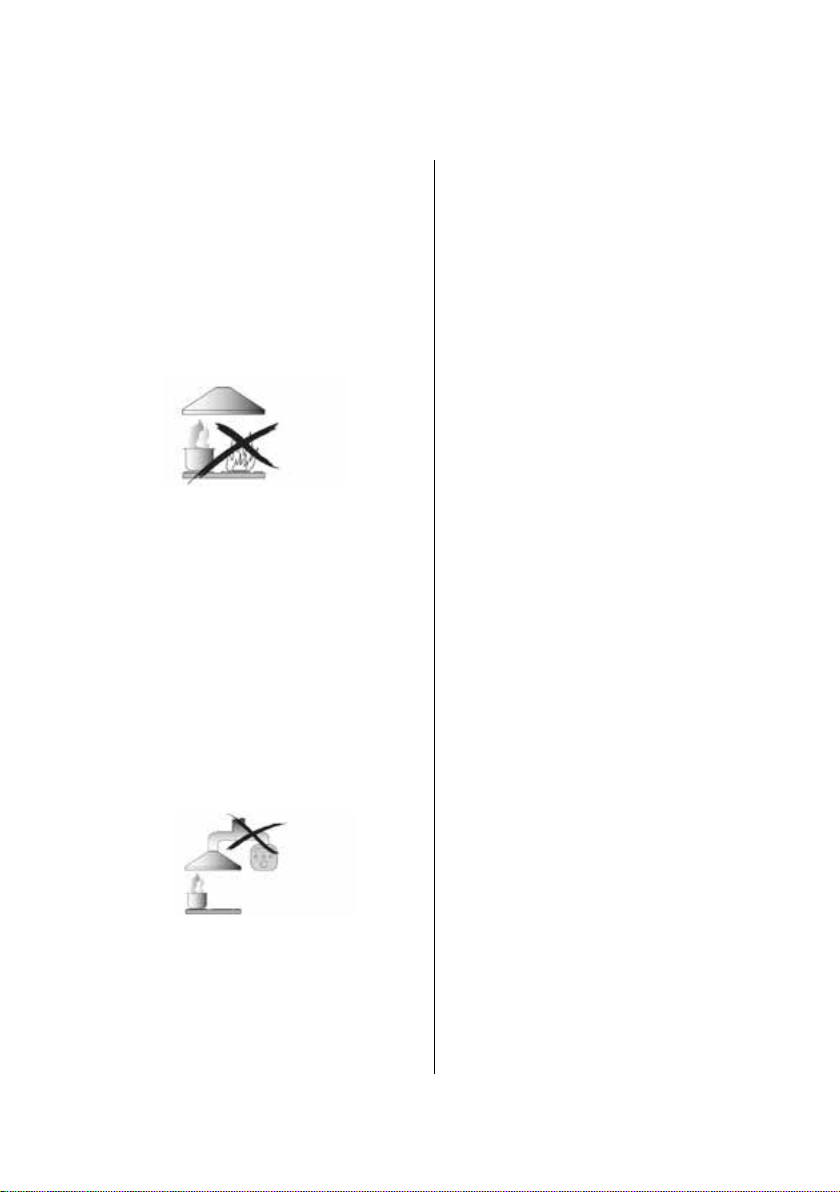
●Do not leave frying pans unattended
during use because overheated fats or
oils might catch fire.
●Never leave naked flames under the
Rangehood.
●If the Rangehood is damaged, do not
attempt to use.
●Do not flambé under the Rangehood.
●CAUTION: Accessible parts may
become hot when used with cooking
appliances.
●The minimum distance between the
supporting surface for the cooking
vessels on the hob and the lowest part
of the Rangehood. (When the
Rangehood is located above a gas
appliance, this distance shall be at
least 75 cm)
●The air must not be discharged into a
flue that is used for exhausting fumes
from appliances burning gas or other
fuels.
Things to always do:
●Important! Always switch off the
electricity supply at the mains during
installation and maintenance such as
light bulb replacement.
●The Rangehood must be installed in
accordance with the installation
instructions and all measurements
followed.
●All installation work must be carried out
by a competent person or qualified
electrician.
●Please dispose of the packing material
carefully. Children are vulnerable to it.
● Pay attention to the sharp edges
inside the Rangehood especially
during installation and cleaning.
●When the Rangehood is located above
a gas appliance, the minimu m
distance between the supporting
surface for the cooking vessels on the
hob and the lowest part of the
Rangehood that distance must be:
Gas cookers: 75 cm
Electric cookers: 65 cm
Coal or oil cookers: 75 cm
●Make sure the ducting has no bends
sharper than 90 degrees as this will
reduce the efficiency of the
Rangehood.
●Warning: Failure to install the screws or
fixing device in accordance with these
instructions may result in electrical
hazards
●Warning: Before obtaining access to
terminals, all supply circuits must be
disconnected.
Things to always do:
●Always put lids on pots and pans when
cooking on a gas cooker.
●When in extraction mode, air in the
room is being removed by the
Rangehood. Please make sure that
proper ventilation measures are being
observed. The Rangehood removes
odours from room but not steam.
3
Page 4
●Rangehood is for domestic use only.
●If the supply cord is damaged, it must
be replaced by the manufacturer, its
service agent or similarly qualified
persons in order to avoid a hazard.
●This appliance is not intended for
use by persons (including children)
with reduced physical, sensory or
mental capabilities, or lack of
experience and knowledge, unless
they have been given supervision or
instruction concerning use of the
appliance by a person responsible for
their safety.
●Warning: Before obtaining access to
terminals, all supply circuits must be
disconnected.
Things to always do:
●Caution: The appliance and its
accessible parts can become hot
during operation. Be careful to avoid
touching the heating elements.
Children younger than 8 years old
should stay away unless they are
under permanent supervision.
●There shall be adequate ventilation of
the room when the Rangehood is
used at the same time as appliances
burning gas or other fuels.
●There is a fire risk if cleaning is not
carried out in accordance with the
instructions
●Regulations concerning the discharge
of air have to be fulfilled.
●Clean your appliance periodically by
following the method given in the
chapter MAINTENANCE.
●For safety reason, please use only the
same size of fixing or mounting screw
which are recommended in this
instruction manual.
●Regarding the details about the method
and frequency of cleaning, please
refer to maintenance and cleaning
section in the instruction manual.
●Cleaning and user maintenance shall
not be made by children without
supervision.
●When the Rangehood and appliances
supplied with energy other than
electricity are simultaneously in
operation, the negative pressure in the
room must not exceed 4 Pa (4 x 10⁻⁵
bar).
●WARNING: Danger of fire: do not store
items on the cooking surfaces.
●A steam cleaner is not to be used.
●NEVER try to extinguish a fire with
water, but switch off the appliance and
then cover flame e.g. with a lid or a
fire blanket.
4
Page 5

IMPORTANT INFORMATION
Points to consider for installation
1. Before installation, please ensure the area is clean to avoid suction of the
remaining bits of debris and dust.
2. Please ensure that the fan motor is firmly secured to either a flat surface such
as an MDF panel affixed across the ceiling rafters, or fixed to the ceiling rafters
themselves. Ensure the fan motor is level and there is no vibration when in use.
3. The location of the fan unit shall allow access for maintenance and repair.
Permanent fixed means of access is required where the fan unit location is
beyond the extent of normal steps or ladders.
4. After installation, make sure that the main body is level to avoid grease
collection at one end.
5. Please note the dimensions of the fan motor for installation purposes.
6. The fan motor should be secured using the supplied brackets and screws.
5
Page 6
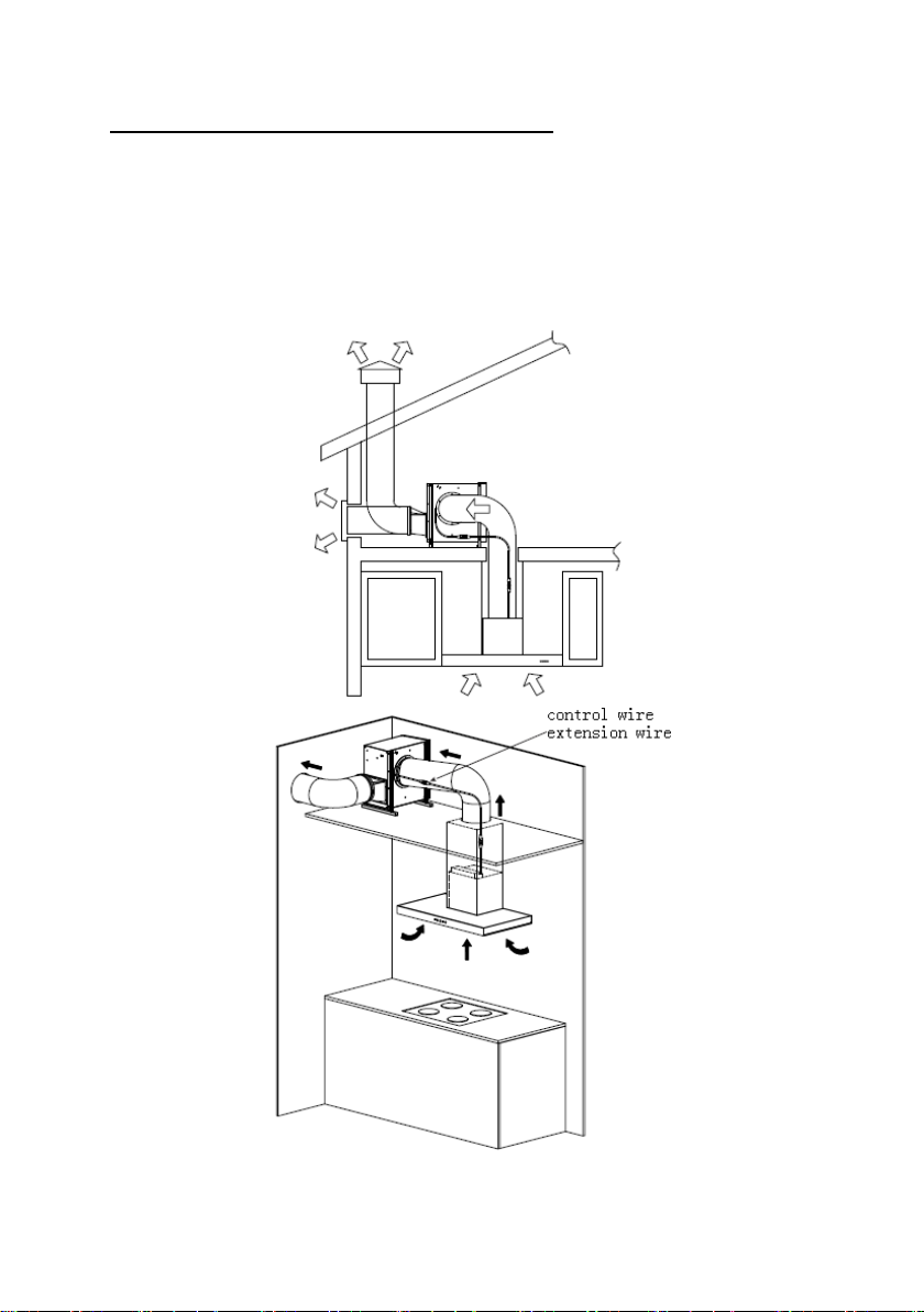
INSTALLAT ION - ROOF CAVITY MOTOR VERSION
Schematic diagram
1. Connect the Rangehood main body with the external cabinet by control wire, to
achieve power on and off, and also speed switching.
2. The control wire is separated into 3 parts, the first two parts are fixed onto the main
body and external cabinet, while the middle part is extension wire.
3. The Rangehood main body and the external cabinet will exhaust the smoke to
outdoor after installing the expansion pipe.
6
Page 7
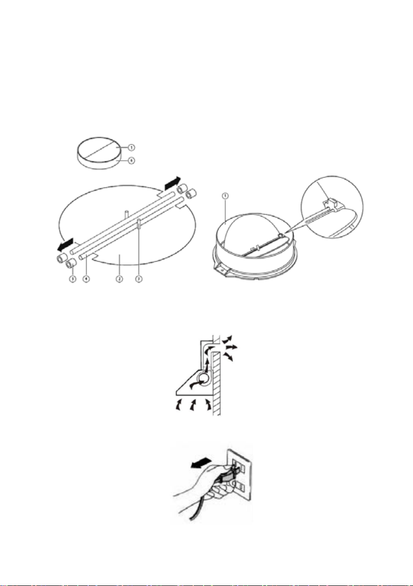
MOUNTING OF THE V-FLAP
If the Rangehood does not have an assembled V-flap 1, you should mount the half-
parts to its body. The images only show an example of how to mount the V-flap, the
outlet may be various according to different models and configuration.
To mount the V-flap 1 you should:
• Mount two half-parts 2 into the body 6
• a pin 3 should be top oriented;
• the axis 4 should be inserted in the holes 5 on body;
• repeat all the operations for the 2nd half-part
INSTALLAT ION
If you have an outlet to the outside, your Rangehood can be connected as below
picture by means of an extraction duct (enamel, aluminium, flexible pipe or nonflammable material with an interior diameter of 220mm)
1. Before installation, turn the unit off and unplug it from the outlet.
7
Page 8

2. The Rangehood should be placed at a distance of 65~75cm above the cooking
surface for best effect.
3. Install the hook on a suitable place once the installation height is fixed, and keep it
in line. The fixed position of the inside chimney bracket is the place of chimney.
See pic 2.
4. 1) Equip the outlet connecting cover onto the cabinet top, and screw 6 pcs 4*8mm
screws to fix it.
2) Install the outlet seal ring and outlet, and fix them with 8 pcs 4*14mm screws,
see pic 3. Then hang the hood on the hook. See pic 4.
8
Page 9

5. Fix the outside chimney bracket on the outside chimney by 2 pcs 4*8mm screws,
and be sure that the inside chimney can be adjusted the height in it freely, put the
chimneys onto the Rangehood. See pic 5.
6. Equip the chimneys, fix the outside chimney bracket with 2 pcs 4*40mm screws, and
use 2 pcs 4*30mm screws to fix the hood body. See pic 6.
7. Unscrew the 8 pcs ST4*14mm screws, and dismantle the outlet mesh cover, see
pic 7. Note: There is no need to unscrew the 4 screws showing on pic 8.
8. Install the outlet seal ring and outlet, using the 8 pcs ST4*14mm screws in step 7 to
fix them. See pic 9.
9. Install case installation bracket, and fix with 4 pcs M4 screws, spring washers and
gaskets. See pic 10.
9
Page 10

10. Screw 4 pcs 4*30mm screws to fix the external cabinet onto the ceiling. See pic 11
& 12.
11. Install the expansion pipe and fix it with cable tie. See pic 13.
12. Equip the expansion pipe to the outlet, and fix with cable tie. Lead one end of the
expansion pipe which install on the external cabinet outlet to the outside. Both end
of the motor extension wire should connect with the external cabinet control wire and
the control wire of the main body top. The plastic base of the control wire should be
plugged to the bottom, and make the buckle to tight status. See pic 14.
10
Page 11

Note: You need to loosen the connecting wire before repair, follow the steps as below:
a. Rotate the lock catch of the connecting wire following the arrow direction.
b. Pull out the connector.
13. Adjust the height of the inside chimney to the position of the inside chimney bracket
and fix on it by 2 pcs ST4*8mm screws. See pic 15.
14. Installation is finished. See Pic 16.
HINTS FOR EXHAUST DUCT INSTALLATION
The following rules must be strictly followed to obtain optimal air extraction:
• Keep expansion pipe short and straight.
• Do not reduce the size or restrict expansion pipe.
• When using expansion pipe always install the pipe pulled taut to minimize pressure
loss.
• Failure to observe these basic instructions will reduce the performance and increase
noise levels of the Rangehood.
• Any installation work must be carried out by a qualified electrician or competent
person.
11
Page 12

INSTALLAT ION - EXTERNAL WALL HUNG MOTOR VERSION
Schematic diagram
1. Connect the Rangehood main body with the external cabinet by control wire, to
achieve power on and off, and also speed switching.
2. The control wire is separated into 3 parts, the first two parts are fixed onto the main
body and external cabinet, while the middle part is extension wire.
3. The Rangehood main body and the external cabinet will exhaust the smoke to
outdoor after installing the expansion pipe.
12
Page 13

MOUNTING OF THE V-FLAP
If the Rangehood does not have an assembled V-flap 1, you should mount the half-
parts to its body. The images only show an example of how to mount the V-flap, the
outlet may be various according to different models and configuration.
To mount the V-flap 1 you should:
• Mount two half-parts 2 into the body 6
• a pin 3 should be top oriented;
• the axis 4 should be inserted in the holes 5 on body;
• repeat all the operations for the 2nd half-part
INSTALLAT ION
If you have an outlet to the outside, your Rangehood can be connected as below
picture by means of an extraction duct (enamel, aluminium, flexible pipe or nonflammable material with an interior diameter of 220mm)
1. Before installation, turn the unit off and unplug it from the outlet.
13
Page 14

2. The Rangehood should be placed at a distance of 65~75cm above the cooking
surface for best effect.
3. Install the hook on a suitable place once the installation height is fixed, and keep it
in line. The fixed position of the inside chimney bracket is the place of chimney. See
pic 2.
4.1) Equip the outlet connecting cover onto the cabinet top, and screw 6 pcs 4*8mm
screws to fix it.
2) Install the outlet seal ring and outlet, and fix them with 8 pcs 4*14mm screws,
see pic 3. Then hang the hood on the hook. See pic 4.
14
Page 15

5. Fix the outside chimney bracket on the outside chimney by 2 pcs 4*8mm screws,
and be sure that the inside chimney can be adjusted the height in it freely, put the
chimneys onto the Rangehood. See pic 5.
6. Equip the chimneys, fix the outside chimney bracket with 2 pcs 4*40mm screws,
and use 2 pcs 4*30mm screws to fix the hood body. See pic 6.
7. Install the wall mounted bracket, and fix with 4 pcs M4 screws, spring washers and
gaskets. See pic 7.
8. Equip the expansion pipe, and use stainless steel hoop to fix it. See pic 8.
9. Make a φ220mm hole on the wall, and let the expansion pipe and motor connecting
wire to across the wall together. Screw 4 pcs wall plugs into the wall, and then fix the
cabinet on the wall with 4 pcs 4*30mm screws. See pic 9.
15
Page 16

10. Install the expansion pipe onto the main body outlet and fix it with cable tie.
Connect the motor extension wire both end with the external cabinet control wire and
main body top control wire. The plastic base of the control wire should be plugged to
the bottom, and make the bucket to tight status. See pic 10.
Note: You need to loosen the connecting wire before repair, follow the steps as below:
c. Rotate the lock catch of the connecting wire following the arrow direction.
d. Pull out the connector.
16
Page 17

11. Adjust the height of the inside chimney to the position of the inside chimney
bracket and fix on it by 2 pcs ST4*8mm screws. See pic 11.
12. Installation is finished. See Pic 12.
HINTS FOR EXHAUST DUCT INSTALLATION
The following rules must be strictly followed to obtain optimal air extraction:
• Keep expansion pipe short and straight.
• Do not reduce the size or restrict expansion pipe.
• When using expansion pipe always install the pipe pulled taut to minimize pressure
loss.
• Failure to observe these basic instructions will reduce the performance and increase
noise levels of the Rangehood.
• Any installation work must be carried out by a qualified electrician or competent
person.
•Do not connect the ducting system of the hood to any existing ventilation system
which is being used for any other appliance, such as warmer tube, gas tube, hot wind
tube.
•The angle of the bend of the expansion pipe should not be less than 120º; you must
direct the pipe horizontally, or, alternatively, the pipe should go up from the initial point
and should be led to an outer wall.
•Ensure the expansion pipe selected for installation complies with relevant standards
and is fire retardant.
17
Page 18

WARNING:
For safety reason, please use only the same size of fixing
or mounting screw which are recommended in this
Failure to install the screws or fixing device in accordance
Start Using Your Rangehood
LED touch control
instruction manual.
with these instructions may result in electrical hazards.
1. Press the “Power” button, the button controls the “on” & “off” of the hood.
2. Press the button “Speed” time after time, the motor runs as low / mid / high / low /
mid…, the speed runs circularly; and the LED display will indicate as 1-2-3-1-2…
circularly.
3. Press “Light” button, the light is on, press this button again, the light is off. Please
note the Lamp is not under control of the on/off button.
4. When the hood is working, if press the “Timer ” button, the hood will go into the status
of acquiescent working (acquiescent time is 9mins), and then, LED display will be
shown 9.8.7.6 ...decreasing by 1, when time is up, the hood will be off automatically
and the lamp will extinguish. If pressing “Time r” button, the hood will go in or go out
“Timer ” function.
18
Page 19

TROUBLESHOOTING
Fan switch turned off
Select a fan switch position.
Fan switch failed
Contact service centre.
Motor failed
Contact service centre.
Power cord loose or
disconnected
Refit cord to power outlet.
Switch power outlet on.
Replace globes as per this
instruction.
The distance between the
too far
The Rangehood
inclines
The fixing screw not tight
enough
Tighten the hanging screw and
make it horizontal.
Fault Possible Cause Solution
Light on, but motor
does not work
Light does not
House fuses blown Reset/Replace fuses.
work, motor does
not work
Broken/Faulty globes
Lights not working
Insufficient suction
Rangehood and the gas top is
Refit the Rangehood to the
correct distance.
NOTE:
Any electrical repairs to this appliance must conform to your local, state and
federal laws. Please contact the service centre if in any doubt before
undertaking any of the above. Always disconnect the unit from the power
source when opening the unit.
MAINTENANCE AND CLEANING
Caution:
• Before maintenance or cleaning is carried out, the
Rangehood should be disconnected from the main power
supply. Ensure that the Rangehood is switched off at the wall
socket and the plug removed.
• External surfaces are susceptible to scratches and
abrasions, so please follow the cleaning instructions to
ensure the best possible result is achieved without damage.
GENERAL
Cleaning and maintenance should be carried out with the appliance cold especially
when cleaning. Avoid leaving alkaline or acid substances (lemon juice, vinegar etc.) on
the surfaces.
STAINLESS STEEL
The stainless steel must be cleaned regularly (e.g. Weekly) to ensure long life
expectancy. Dry with a clean soft cloth. A specialised stainless steel cleaning fluid may
be used.
NOTE:
Ensure that wiping is done along with the grain of the stainless steel to prevent any
unsightly crisscross scratching patterns from appearing.
19
Page 20

CONTROL PANEL SURFACE
The inlay control panel can be cleaned using warm soapy water. Ensure the cloth is
clean and well wrung before cleaning. Use a dry soft cloth to remove any excess
moisture left after cleaning.
Important
Using neutral detergents and avoid using harsh cleaning chemicals, strong household
detergents or products containing abrasives, as this will affect the appliance
appearance and potentially remove any printing of artwork on the control panel and
will void manufactures’ warranty.
GREASE MESH FILTERS
The mesh filters can be cleaned by hand. Soak them for about 3 minutes in water with
a grease-loosening detergent then brush it gently with a soft brush. Please do not
apply too much pressure, avoid to damage it. (Leave to dry naturally out of direct sun
light)
Filters should be washed separately to crockery and kitchen utensils. it is advisable
not to use rinse aid.
INSTALLING GREASE MESH FILTERS
• To install filters for the following four steps.
- Angle the filter into slots at the back of the hood.
- Push the button on handle of the filter.
- Release the handle once the filter fits into a resting position.
- Repeat to install all filters.
20
Page 21

BULB REPLACEMENT
Important :
The bulb must be replaced by the manufacturer, its service
can reduce the life of the globe.
agent or similarly qualified persons.
Always switch off the electricity supply before carrying out
any operations on the appliance. When handling bulb, make
sure it is completely cooldown before any direct contact to
hands.
When handling globes hold with a cloth or gloves to ensure
perspiration does not come in contact with the globe as this
Changing the LED light
Note:
• Before changing the lights, make sure that the appliance is plugged off.
• Protect against danger when changing lights, such as wearing gloves.
• Light replacement should be carried out by qualified service personnel only.
• Switch the unit off and pull out the plug first.
• Loose the 4 pcs 4X10MM screws at the back of case, and then take out the
outer glass.
• Loose the 2 pcs screws on the lamp bracket, and then change the LED light.
See pic below.
• Remove the grease filter.
• Unscrew the 4pcs screws on the LED light strip bracket by cross screwdriver,
dismantle the LED light strip and pull out the terminal of the light connecting
wire. See pic 1. (Note: It will need to dismantle the front panel first for models
cannot directly take down the light strip.)
• Apply the reverse procedure to install the light strip back.
•ILCOS D code for this lamp is: DSL-7-S-650
– Max wattage: 7 W
– Voltage range: DC 12V
21
Page 22

22
Page 23

ENVIRONMENTAL PROTECTION:
This product is marked with the symbol on the selective sorting of
please contact your local or regional authorities.
waste electronic equipment. This means that this product must not
be disposed of with household waste but must be supported by a
system of selective collection in accordance with Directive
2012/19/EU. It will then be recycled or dismantled to minimize
impacts on the environment, electrical and electronic products are
potentially dangerous for the environment and human health due to
the presence of hazardous substances. For more information,
NOTE:
The following shows how to reduce total environmental impact (e.g. energy use) of the
cooking process).
(1) Install the Rangehood in a proper place where there is efficient ventilation.
(2) Clean the Rangehood regularly so as not to block the airway.
(3) Remember to switch off the Rangehood light after cooking.
(4) Remember to switch off the Rangehood after cooking.
INFORMATION FOR DISMANTLING
Do not dismantle the appliance in a way which is not shown in the user manual. The
appliance could not be dismantled by user. At the end of life, the appliance should
not be disposed of with household waste. Check with you Local Authority or retainer
for recycling advice.
23
Page 24

Distributed by:
Glen Dimplex Australia Pt y Ltd
1340 Ferntree Gully Road, Scoresby VIC 3179
Tel: 1800 444 357
Email: customercare@hapl.com.au
Website: www.euromaid.com.au
 Loading...