

Page 1
USERS INSTRUCTIONS
INSTALLATION AND USER INSTRUCTIONS
Tipolitografia Montagnani - Modena - Italy - Cod. 537192 - 0606
NOTE TO INSTALLER: LEAVE THE OWNER’S GUIDE MANUAL WITH THE APPLIANCE.
(Keep For Future Reference)
- AU -
16
a blown fuse or tripped circuit breaker.
• Hotplate not properly grounded or polarized. This can effect
ignition on spark ignition models.
• Check for power wattage.
• Gas supply not connected or not turned on.
• A pan is sitting on the burner grate. This may partially clock the
free air flow needed for combustion. Remove the pan and try
again.
• Burners not adjusted properly.
• Food clogging burners or burner assembly misaligned. Make
sure that burner ports on side of burner are not clogged. Make
sure that burners are positioned correctly.
WHEN YOU CALL FOR SERVICE
When you call for service or order parts for you Hotplate be sure
to give:
1. MODEL
2. SERIAL NUMBER
3. COLOUR
4. PART NAME and/or description of problem
5. YOUR FULL NAME, ADDRESS, and HOME TELEPHONE
NUMBER and BUSINESS TELEPHONE NUMBER IF
APPROPRIATE
6."FOR NUMBER SERVICE CONTACT" SEE DATA LABEL
LOCATED ON BASE OF THE APPLIANCE
TROUBLE - SHOOTING GUIDE
ABNORMAL OPERATION
Any of the following are considered to be abnormal operation and
may require servicing:
Yellow tipping of the hob burner flame.
Shooting up of cooking utensils.
Burners not igniting properly.
Burners failing to remain alight.
Burners extinguished by cupboard doors.
Gas valves, which are difficult to turn.
In case the appliance fails to operate correctly, contact the
authorised service provider in your area.Burners extinguished by
cupboard doors.
Gas valves, which are difficult to turn.
In case the appliance fails to operate correctly, call the number
on the data label located on the front of this manual.
BEFORE YOU CALL FOR SERVICING
A review of the following may save you a service call and if not
it may help you explain the malfunction to the service person.
Read the operating instructions carefully. Be sure you know how
to opera the appliance.
If base of cooking utensils show signs of carbon (soot) deposit,
this could indicate an incorrect burner flame. Please contact local
service number (refer to the data label on the front of this instruciton
manual).
THE BURNER DOES NOT LIGHT
• Check to ensure Hotplate cord is plugged into outlet. Check for
Maintenance schedule:
To ensure the appliance continues to operate at peak performance,
we recommend a routine service call every 2 years for the life of
the appliance.
Page 2
15
CLEANING
Cleaning should only be carried out when the appliance is COOL
and is SWITCHED OFF. Always clean off spillage as quickly as
possible; to prevent burning which will make removal more difficult.
Do not use harsh abrasive rags or products; they Can seriously
damage the appliance. For Hotplate top use a wet cloth with liquid
detergent and dry by means of a soft cloth. For electric hot plates;
wipe with a clean cloth soaked in hot soapy water to remove
excess spillage. For stubborn marks use a mild paste cleaner or
moist soap pad. Dry the plate thoroughly after cleaning. To maintain
the plates, rub the surface with a little neutral oil periodically.
Ensure all cleaning agents are thoroughly removed.
FOR YOUR SAFETY
1) If you smell gas:
—open the windows
—don’t touch electrical switches
—extinguish any open flame
—never use a flame to locate such a leak, use soapy water
only
—contact authorised technician.
2) Keep children away from the appliance: they can suffer serious
personal harm by touching the hot parts of the appliance and
the pans.
3) Don’t store items that are attractive to children above or near
the appliance.
4) Do not store or use gasoline or other flammable vapours, liquid
or items in the vicinity of this or any other appliance.
5) Do not use the appliance as a space heater, especially in a
small room, a caravan or a boat.
6) In order to avoid any unintentional fall down, pan handles
should be turned to the back of the cooker, not out to the room
or over adjacent burners.
7) When cooking, don’t wear clothes with flammable sleeves.
8) In case of fire, close immediately the main valve of the gas
pipe line and never pour water on hot oil.
When this appliance is installed in marine craft or in caravans,
it shall not be used as a space heater.
WARNING
Before its first use or, if the plate has not been used for some
time, it is necessary to eliminate the humidity absorbed by the
insulating layer mixture. To provide for the drying of such, engage
the electric plate for 30 minutes on position 1 of the switch.
During the use or the cleaning of the appliance, pay attention that
water or any liquid does not enter into the appliance through the
holes around the rods of the switches. Water or juice or sauce
will produce dangerous short-circuits and can seriously damage
the working of the Hotplate. The base of the Hotplate casing will
become hot in use and must not be touched through a drawer or
cupboard openings.
USERS INSTRUCTIONS
Page 3
14 3
USERS INSTRUCTIONS
INDEX
INSTALLATION INTRUCTIONS...................pag. 4 - 7
SERVICE INSTRUCTIONS..........................pag. 8 - 9
USERS INSTRUCTIONS.............................pag. 10 - 16
ENVIRONMENTAL WARNING
Waste packaging
Do not throw the packaging of your appliance into the dustbin, but pick
out the different materials (e.g. foil, paperboard, polystyrene) according
to the local rules for rubbish elimination.
This appliance must only be used for the purpose of domestic cooking.
WARNING
* This appliance is not intended for use by young children or infirm
persons without supervision.
* Young children should be supervised to ensure that they do not play
with the appliance.
WHERE THIS APPLIANCE IS INSTALLED IN MARINE CRAFT OR
IN CARAVANS, IT SHALL NOT BE USED AS A SPACE HEATER.
Congratulations on the purchase of your new Hot Plate
which is built to give you years of satisfactory service and pleasure when properly cared for and used.
Producing an efficient Hotplate that conserves energy required a considerable investment of time, effort and money.
Your Hotplate is engineered to surpass all performance and safety requirements. However, safety is also YOUR responsibility
through proper use and care.
With this in mind, it is important that you read this booklet. Acquaint yourself with the features and follow the use and care
suggestions carefully for complete satisfaction.
Remember: only authorised personnel must make the necessary gas and electrical connections.
Be sure you know the correct model and serial model of your Hotplate. The data plate is sealed on the outside of the lower
case of your Hotplate.
RECORD HERE FOR EASY REFERENCE
Model Colour Serial Number
Installation Date
Dealer's Name and Address
USING THE ELECTRIC HOB
USING THE HOT PLATES
The Hotplate may have two different types of hot plates; rapid
action plate compared with the standard one, offers the advantage
of faster heating and more power for faster cooking The hot plates
operate at a fixed setting according to the position selected on
the control knob. To switch on, turn the appropriate control knob
to the required setting (setting 6 operates at full rate). To switch
off, turn the control knob to the OFF position (marked • ). The
electric plate working is indicated by a warning light on the control
panel. Turn the appropriate control knob clockwise to the required
setting according to the cooking task. The following table may be
used as a guide for settings.
Setting Cooking Tasks
1 - Very low Warming, melting butter or chocolate.
2 - Low Stews, milk pudding, cream sauces, fried
eggs.
3 - Low-medium Stewed fruit, frozen foods, boiling milk.
4 - Medium Boiled potatoes, fresh vegetables soups, fish.
5 - High Large quantities of stew etc. fish, omelettes,
steaks.
6 - Fast Steaks, escalopes, frying, boiling water.
WARNING
Always use pans with a flat base to ensure even contact with the
hotplate. The correct size of pan should be used so that the whole
of the hot plate is covered. Never switch on the hotplates without
a pan in position, as the hot plate will become distorted. To ensure
even contact and to prolong the life of hot plates, the base of the
pans should be kept clean and dry. Do not use “split pans” as
uneven heating of the hot plates will occur. For safety, keep
saucepan handles turned to a safe position so that they are out
of reach of small children and cannot be accidentally knocked.
Take care never to reach over an electric hotplate, and allow
time to cool before attempting to clean.
DO NOT SPRAY AEROSOLS IN THE VICINITY OF THIS APPLIANCE
WHILE IT IS IN OPERATION.
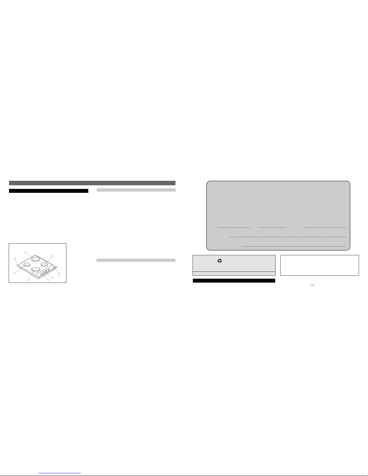
DESCRIPTION
ELECTRIC PLATE
A Work-top
F Electric plate Ø 180 - left
I Electric plate Ø 145 - right
L Holder for mark label
N Warning light for plate
O Electric knob
R Electric plate Ø 180 - right
T Electric plate Ø 145 - left
M Holder for mark label
A
R
I
L
N
O
T
F
Page 4

4 13
INSTALLATIONS INSTRUCTIONS
IMPORTANT NOTICE TO THE INSTALLER
GAS CONNECTION
The appliance shall be installed by an authorized person in
accordance with the manufacturer’s installation instructions,
relevant local fitting regulations, municipal building regulations,
the AS 5601 ( AGA 601 ) gas installations. For gas burning
appliances and equipment and other relevant statutory code band
regulations. If you have some doubts, please contact the authorities
for confirmation concerning the characteristics of the gas and
electricity output.
This appliance can be connected with rigid pipe as specified in
AS5601 table 3.1 or with a Flexible Hose which complies with
AS/ANZ 1869 (AGA Approved), 10mm ID, class B or D, no more
that 1.2m long and in accordance with AS5601. Ensure that the
Hose does not contact the hot surfaces of the hotplate or
any oven that may be installed underneath or next to the
hotplate. The Hose should not be subjected to abrasion,
kinking or permanent deformation and should be able to be
inspected along its entire length. Unions compatible with the
hose fittings must be used and connections tested for gas
leaks. The supply connection point shall be accessible with
the appliance installed.
The appliance is generally preset for natural gas (so no other
adjustment is necessary) and equipped with a regulator with
pressure test point. Ensure that all foreign matter has been cleared
from the gas supply line and also purge all air from the gas system.
Connect to regulator, tighten and check the installation to ensure
no gas leaks occur. Check gas pressure, note the correct setting
from the data plate sealed on the lower side of the case. A duplicate
This appliance from the factory suitable for NATURAL gas but, if
necessary, can be adjusted for U-LPG by an authorised person.
4 BURNER UNIT / 4 ELECTRIC PLATES
DIMENSIONS
Overall Height above work surface......................45 mm (13/4 in)
Width........................................................580 mm (22 13/16 in)
Depth........................................................500 mm (19 11/16 in)
Minimum space above hotplate .........................600 mm (24 in)
CONNECTIONS
Gas..............................................................RC 1/2 (1/2" B.S.P.)
Electric ignition ..........1 mm2 3 core cable (3 amp fuse required)
4 Electric plates ..................................... 2.5 mm
2
3 core cable
Should conform to local gas authority requirements.
Also refer to rangehood manufacturers recommendations.
GAS HOT PLATE
USERS INSTRUCTIONS
Electric diagram
342 1 3
4
2
1
21 4 5
S
1
2
3
4
S
1
2
3
4
N
L
342 1 3
4
2
1
S
1
2
3
4
S
1
2
3
4
N
L
HOB
3
1
1 Electric plate - 2 Electric plate commutator - 3 Warning light plate - 4 Terminal box
yellow-green
SERVICING FOR HOT PLATES
label is supplied and adhered to the front of this instruction manual.
Four burner models: “burner pressure is to be set at 1 kpa with
wok burner only operating at full rate.Apply a manometer to the
test nipple and reset the regulator if necessary.
Do not forget to replace the test nipple screw and to leave the
instructions book with the user.
For conversion to U-LPG gas, please operate as specified in the
paragraph GAS CONVERSION AND ADJUSTMENT (Page. 8).
Important: several parts are protected with a special anti-scratch
film. Please remove it before use.
NO
NO
Y
Z
WARNING: THIS APPLIANCE MUST BE EARTHED.
NOTE: For cut out dimensions see Pages 5 .
These instructions are for a authorised person when it is necessary
to repair or adjust internal parts of the appliance.
WARNINGS
Before performing any repair or operation, switch the appliance
off.
In case it is necessary to repair or replace the inside components,
act as follows:
DISASSEMBLY OF WORK-TOP
3) On the lower plate of the hob, on the outside there are some
visible screw-nuts fixing the electrical plates to the chassis.
Once these screw-nuts are unscrewed, it is possible to replace
the components inside the hob (see picture below).
1) Remove the control knobs (pulling up) from the electric the
switches
2) Disassemble the work-top from the cabinet unscrewing screws
Z blocking locking bridles Y.
Remove the hob from the top.
17
Page 5

12 5
INSTALLATIONS INSTRUCTIONS
POSITIONING
The Hotplate unit should be placed in a position free from draughts
and with good light. The unit must not be fitted closer than 30 mm
on left hand side to non-combustible cup boards or wall. Any
adjoining wall surface situated within 200mm from the edge of
any hob burner (refer to diagram below) must be a suitable noncombustible material for a height of 150mm for the entire length
and width of the 'cooking surface area', marked as x in the diagram
below. Any combustible construction above the 'cooking surface
area' must be at least 600mm above the top of the pan supports
and no construction shall be within 450mm above the top of the
pan supports.
INSTALLATION
This Hotplate unit is suitable for installation into a work surface
which has a minimum depth of 600 mm (23 5/8 in) and which is
resistant to temperature up to 90°C). Prepare a cut-out in the work
top with dimensions 480 mm (18 7/8 in) back to front and 560 mm
(21 5/8 in) side to side. The cut-out should not be less than 45 mm
(1 3/4 in) from the rear edge of the work surface.
When the HP is installed there must be a minimum clearance of
110 mm (4 5/16 in) between both the left hand edge and the rear
edge of the Hotplate and any adjacent walls or cabinets (See Fig.
1).
MEASURES APPLIANCE
MEASURES BUILDING-IN
Fig. 1
30
USERS INSTRUCTIONS
After cleaning, make sure
head “C” and covers “A”
and “B” are properly
placed on their seat as
figure “D” and not offcenter as in figure “E”.
ELECTRIC HOTPLATE
IMPORTANT NOTICE TO THE INSTALLER
ELECTRICAL CONNECTION
— All connections to the supply mains should be made by
authorised personnel, in compliance with the regulations in
force.
— The installer will be responsible for complying with the safety
regulations.
— The connection can also be made direct to the supply
mains by Installing-between the supply mains and the
appliance, a switch having minimum 3mm distance
between the poles, suitable for the power Input and
complying with the regulation In force.
— Be sure that the earth wire is not interrupted by the switch.
— The supply cable must not come into contact with any
components the temperature of which exceeds the ambient
temperature by 50°C. Before making any electrical connection,
make sure that:
— the electrical supply is correct for the appliance (see
specifications written on the data plate).
— the fuses and your domestic system are suitable for the
power requirements of the appliance (see data plate).
— easy access to the plug or the switch is ensured once the
appliance is installed.
— NOTE: Brown and black wires are both active.
— Data plate is glued on the underside of the Hotplate.
Important: several parts are protected with a special anti-scratch
film. Please remove it before use.
This appliance must not be connected integrally with any other
appliance on the same sub-circuit.
VENTILATION
Ventilation must be in accordance with AS5601/AG 601 - Gas
Installations. In general, the appliance should have adequate
ventilation for complete combustion of gas, proper flueing and to
maintain temperature of immediate surroundings within safe limits.
x - Cooking Surface Area
X
200 mm
X
PLAN VIEW
CLEANING
Cleaning should only be carried out when the appliance is COOL
and is SWITCHED OFF.
Always clean off spillage as quickly as possible to prevent burning
which will make removal more difficult. Do not use harsh abrasive
rags or products; they can seriously damage the appliance. For
Hotplate top and enamelled pan supports use a wet cloth with
liquid detergent.
Fig. 16A
Fig. 16D
Fig. 16E
Fig. 16
burner cap
locating pegs
notch for electrode
in burner head
electrode
B
A
C
B
A
B
A
Water or juice will produce dangerous short-circuits and can
seriously damage the working of the Hotplate. The base of the
Hotplate casing will become hot in use and must not be touched
through a drawer or cupboard openings.
500
30
580
480
560
Page 6

6 11
INSTALLATIONS INSTRUCTIONS
BENCH TOP FIXINGS
The Hotplate unit is fixed to the work top by metal clamps with a
self-adhesive rubber seal between the unit and the work top.
Ensure that the self-adhesive seal is adhered to the underside of
the unit surface and near as possible to the outer edge of the unit
as illustrated in Figs. 3. Secure the Hotplate to the work top by
means of the fixing clamps and ensure that the joint between the
unit and the work top is airtight by tightening the fixing clamps.
The clamps supplied are suitable for work tops with thickness from
25 to 40 mm. (1 in. to 1 9/16 in).
When the appliance is installed so that the base can be touched,
we recommend fitting a protecting shield. This shield must project
at least 20mm from the lower part of the appliance and be capable
of withstanding the appliance temperatures.
Manual ignition
To light the burner, place a lighted match near the burner and turn
the appropriate knob anticlockwise to the low position (marked
with a small flame symbol ) If burner does not ignite repeat
the procedure. To adjust the burner to the full-on position, turn
the control knob clockwise to the appropriate setting (marked with
a large flame symbol ).
Automatic electric ignition (on some models)
To light the burner of the hob selected for cooking, push in the
corresponding knob and turn in the direction to the fully on position
; when pressed fully in, the spark will be generated automatically,
igniting the burner.
To adjust the burner to the full-on position, turn the control knob
clockwise to the appropriate setting (marked with a large flame
symbol ).
Where this appliance is installed in marine craft or in caravans,
it shall NOT be used as a space heater".
To turn the burner OFF, turn the control knob clockwise to the
OFF setting (marked with a dot ).
APPLIANCES WITH SAFETY VALVE
Follow the same procedure described above to ignite the burners.
In this case, however , once y ou ha ve turned the knob to the open
setting, hold it pressed in for 10 seconds. If for any reason the
burner flame goes out, the safety valve automatically shuts off
the gas supply to the burner in question.
It is recommended that pans suitable to the size of the burner
should de used as follows:
Large burner..................................................................13-24 cm
Small burner..................................................................13-20 cm
Auxiliary burner .............................................................12-18 cm
WARNING
It is not recommended to press push button for ignition if all the
burners are not located in the proper positions. The burner heads,
burner skirts and pan supports are removable for better cleaning:
Always ensure that the burner skirts and heads are replaced
correctly so that the burners function safely and correctly.
During the use of the appliance pay attention that water or any
liquid does not enter into the appliance through the holes of the
burners or around the rods of the valves or the push button
electronic lighter.
USERS INSTRUCTIONS
Fig. 15
Fig. 3
Sealing Strip
min 20
gas hotplate screening plate
Always use pans with all flat base diameter, which are well
balanced and stable in use, a pan which overhangs the hotplate
should not be used. Avoid using old, misshapen pans, or pans
which are unstable when placed on a flat surface. Do not use
“split pans” as they are inherently unstable.
To save gas, always position pans centrally over the burners and
adjust the flames so that they do not lick up the sides of the
panand only the base is heated. Always put lids on a saucepans
and boil only the amount of liquid you use. When the liquid has
boiled adjust the setting to maintain a simmer.
Do not light the burner until the pan is in position and turn off the
burner before removing the pan. In hard water areas, descale
kettles regularly. For safety, keep saucepan handles turned to a
safe position so they are out of reach of small children and cannot
be accidentally knocked.
Page 7

10 7
INSTALLATION INSTRUCTIONS
GAS CONNECTION
The gas inlet is RC 1/2 (1/2 in. B.S.P.) and is situated at the right
hand rear of the appliance, 30mm from the side and 42mm from
the rear of the appliance.. If necessary, cut a suitable hole in the
back of the cabinet for the entry of the gas supply and electric
cable.
IT IS RECOMMENDED THAT A SERVICE TAP AND UNION BE
FITTED ADJACENT TO THE APPLIANCE INLET TO FA CILITA TE
FUTURE SERVICING. ENSURE THE REGULATOR SUPPLIED
(FOR NATURAL GAS) IS FITTED BEFORE APPLIANCE.
Data Label
The Data Label is located base of the appliance. A duplicate Data
Label is supplied to adhere in an accessible area next to the
appliance. This appliance is suitable for Natural Gas and U-LPG;
ensure that the available gas supply matches the Data Label.
VERY IMPORTANT FOR THE INSTALLER
Do not attempt to turn or stress the threaded elbow of the manifold:
you risk damage to this part of the gas appliance which may void
the manufacturers warranty.
BEFORE LEAVING - Check all connections for gas leaks with
soap and water. DO NOT use a naked flame for detecting leaks.
Ignite all burners to ensure correct operation of gas valves, burner
and ignition. Turn gas taps to low flame position and observe
stability of the flame. When satisfied with the hotplate, please
instruct the user on the correct method of operation. In case the
appliance fails to operate correctly after all checks have been
carried out, call the number on the data label located on the front
of this instruction manual.
USER INSTRUCTIONS
USING THE GAS HOT PLATE
NOTE: This hotplate is for domestic use only
Fig. 5
Electric diagram
for multi-sparks
lighter
ELECTRICAL CONNECTION
IMPORTANT
The wires in the mains lead are coloured in accordance with the
following code:
GREEN & YELLOW.........................................................EARTH
BLUE...........................................................................NEUTRAL
BROWN ..............................................................................LIVE
This hotplate is supplied with a plug & cord, simply plug into a 3
pin household socket outlet witch is properly earthed. In order to
avoid hazard, any electrical work performed on this equipment or
its associated wiring, should only be done be persons authorised
by the supplier or similarly qualified persons.
WARNING: THIS APPLIANCE MUST BE EARTHED.
The flexible mains lead and plug must not be in contact with hot
surfaces.
DESCRIPTION
Work-top
Hob left grid
Rapid burner
Semirapid left burner
Electric plate Ø 180 - left
Hob right grid
Semirapid right burner
Electric plate Ø 145 - right
A
B
C
E
F
G
H
I
Holder for mark label
Gas knob
Warning light for plate
Electric knob
Auxiliary burner
Electric plate Ø 180 - right
Triple crown burner
Electric palte Ø 145 - left
L
M
N
O
Q
R
S
T
A
B
C
E
G
H
L
M
Q
A
R
L
N
O
F
T
I
A
B
E
G
H
L
M
Q
S
4 GAS BURNERS WITH TRIPLE CROWN
ELECTRIC PLATES
GAS BURNERS
Page 8

8 9
SERVICE INSTRUCTIONS
SERVICING FOR HOT PLATES
Servicing shall be carried out only by authorised personnel.
- Adjust the intensity of flame by loosening
or tightening screw A.
- For LP gas the screw A must be completely
tightening.
- Make sure that the flame does not
extinguish passing quickly from the max.
flow (big flame) to the minimum flow (little
flame).
- Assemble the knob again.
Fig. 10
GAS CONVERSION AND ADJUSTMENT
When used with natural gas all burners have been preset at our
factory and further adjustment should not be necessary. Conversion
kits to other gases are available from the place of purchase. Do
not attempt to fit the conversion kit yourself. Conversion to LPG
should only be carried out by authorised personnel
REPLACEMENT OF THE INJECTORS
When required to operate on other gas replace the injectors in
accordance with information referred to in chart below (Fig.10).
In order to change the work-top injectors, it is necessary to act
as follows:
- remove the grids
- remove burners and flame-spreaders
- change the injector (see Fig. 8) and replace it with another one
suitable for the new type of gas.
SPECIAL NOTE
When converting from Natural Gas to U-LPG ensure that the NG
regulator is removed and replaced with the Test Point Assembly.
A gas regulator suitable for a supply pressure of 2,75kPa should
be part of the gas tank supply.
After installation or any servicing operation, always ensure that
the appliance is gas sound and that the components are now
operating correctly. Items removed during servicing should be
replaced in the reverse order to their removal.
LOW POSITION ADJUSTMENT
- Switch the burner on, and turn the knob towards the minimum
flow position (small flame).
- Remove the knob from the tap.
- Introduce a little screwdriver in the tap rod (see picture).
Attention: in taps with security valve, the minimum adjusting screw
(A) is placed outside the rod tap (see fig. 7).
Fig. 7
SERVICE INSTRUCTIONS
Fig. 8
A
Gas Type kPa Jet mm Ø Burners Power MJ/h
1,50 Quick 11,50
Natural gas 1,00 1,20 Semiquick 7,00
0,90 Auxiliary 3,80
1,60 T. crown 12,70
0,95 Quick 11,50
U - LPG 2,75 0,73 Semiquick 7,00
0,53 Auxiliary 3,80
1,00 T. crown 12,70
NO
NO
Y
Z
A) On the lower plate of the hob, on the outside there are some
visible screws fixing the burners and the gas manifolds to the
chassis or some screw-nuts fixing the electrical plates for all
electric or combined versions.
Once these screws or screw-nuts are unscrewed, it is possible
to replace the components inside the hob (see picture below).
B)The hob is fixed in its upper part to the burners by means of
some visible screws. If these screws and the nut blocking the
taps to the hob are screwed, it is possible to open the appliance
and to reach the inside components (see picture below).
WARNINGS
Before performing any repair or operation, switch the appliance
off and close the gas tap.
The manufacturer declines all responsibility for any damage to
persons, animals or things caused by failure to observe the rules
indicated above. In case it is necessary to repair or replace the
inside components, act as follows:
DISASSEMBLE OF WORK-TOP
- disconnect the electrical supply cable
- disconnect the gas supply tube
- remove the grids
- remove burners and flame-spreaders
- remove the knobs from the facia-panel
- disassemble the work-top from the cabinet unscrewing screws
Z blocking locking bridles Y .
Remove the hob from the top.
 Loading...