

Page 1
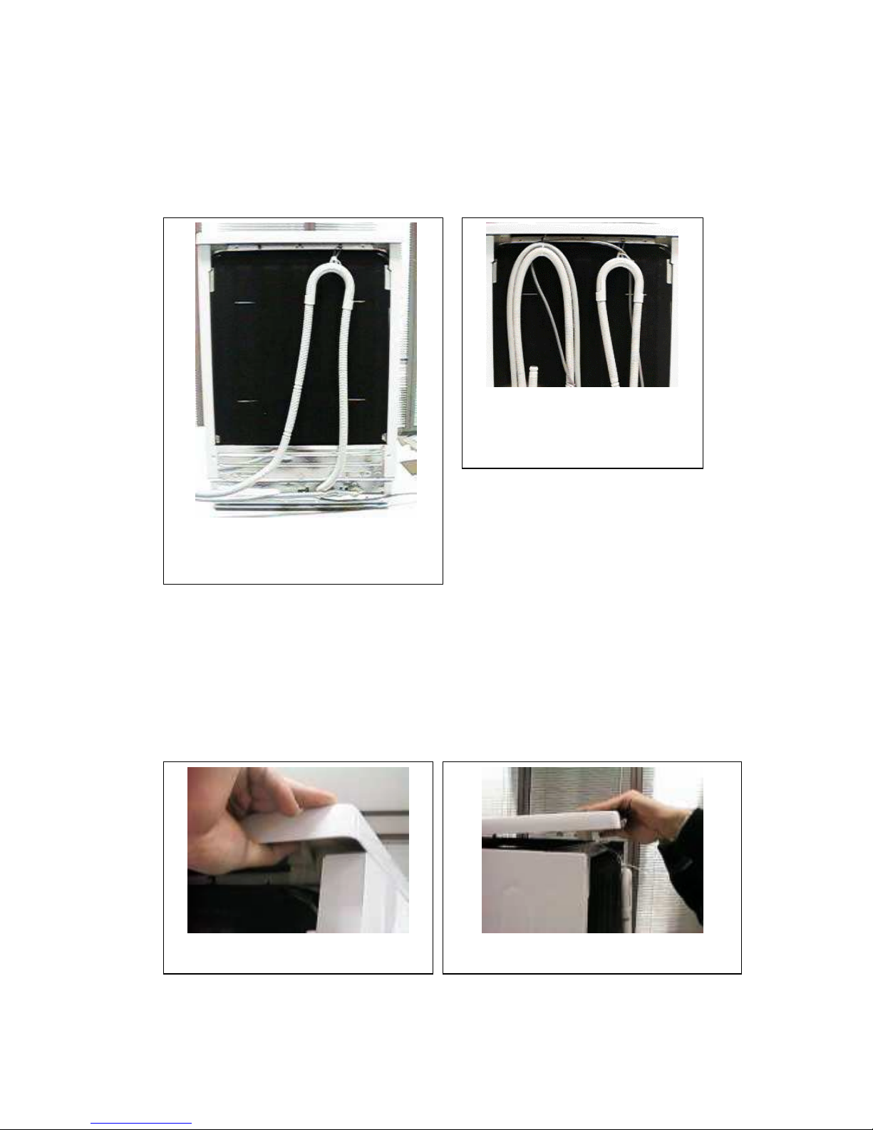
Position of the Drain and Water
Supply hoses before disassembling.
ASSEMBLY AND DISASSEMBLY METHODS FOR KEY
COMPONENTS
1) DRAIN HOSE
For the purpose of avoiding any
siphonage in the drain hose, the
hose is kept at a certain sufficient
level by means of 1 hose clamp.
This clamp should never be
removed while assembling the
machine in the desired position.
When the hose is to be replaced, the unit, which is seen at the right back top
corner of the machine is required to be removed after being cut.
3 wire clamps and 2 plastic hose clamps are removed for dismantling the
drain hose.
2) TOP PLATE
The plate is pulled back for approximately 1 cm. by pressing the latches
located at both sides of the upper plate in upward direction. Afterwards, the
plate is removed by pulling it upwards.
The position of the drain hose during the
assembly of the product.
Manner of opening the latch of the upper
plate.
Manner of removing the upper plate after the
latches are released.
Page 2
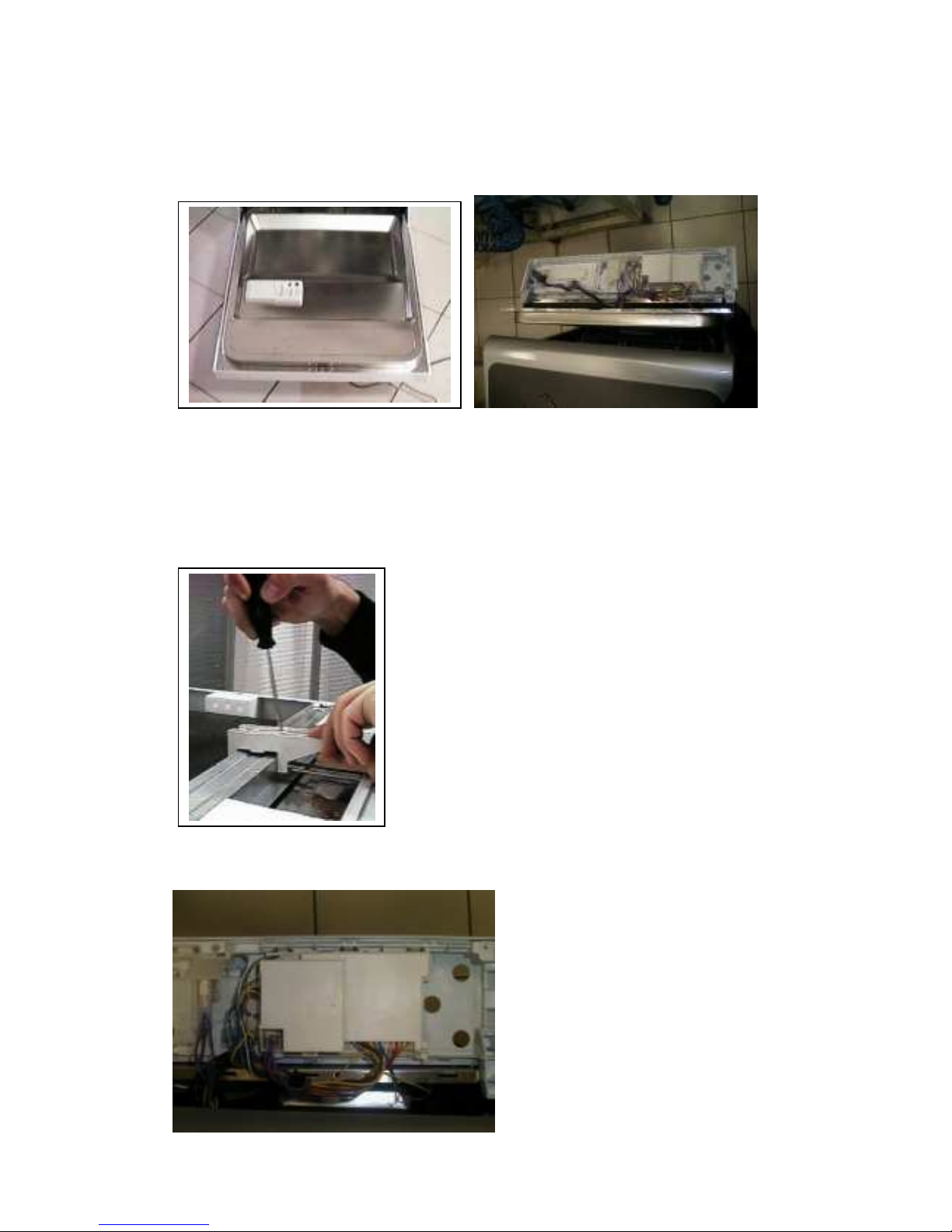
In case the machine is to be installed under the counter, the support of the
upper plate should be dismantled.
3) CONTROL PANEL
The control panel is detached from the inner metal plate, after unscrewing the
6 screws located on the front side of the inner door, as is seen at the photo.
4) TOP PLATE MID SUPPORT
The part can be dissembled by loosening 2
snops screw driver
5) PANEL GROUP
There exists a main board holder
assembled on the back structure
of the panel.
Page 3
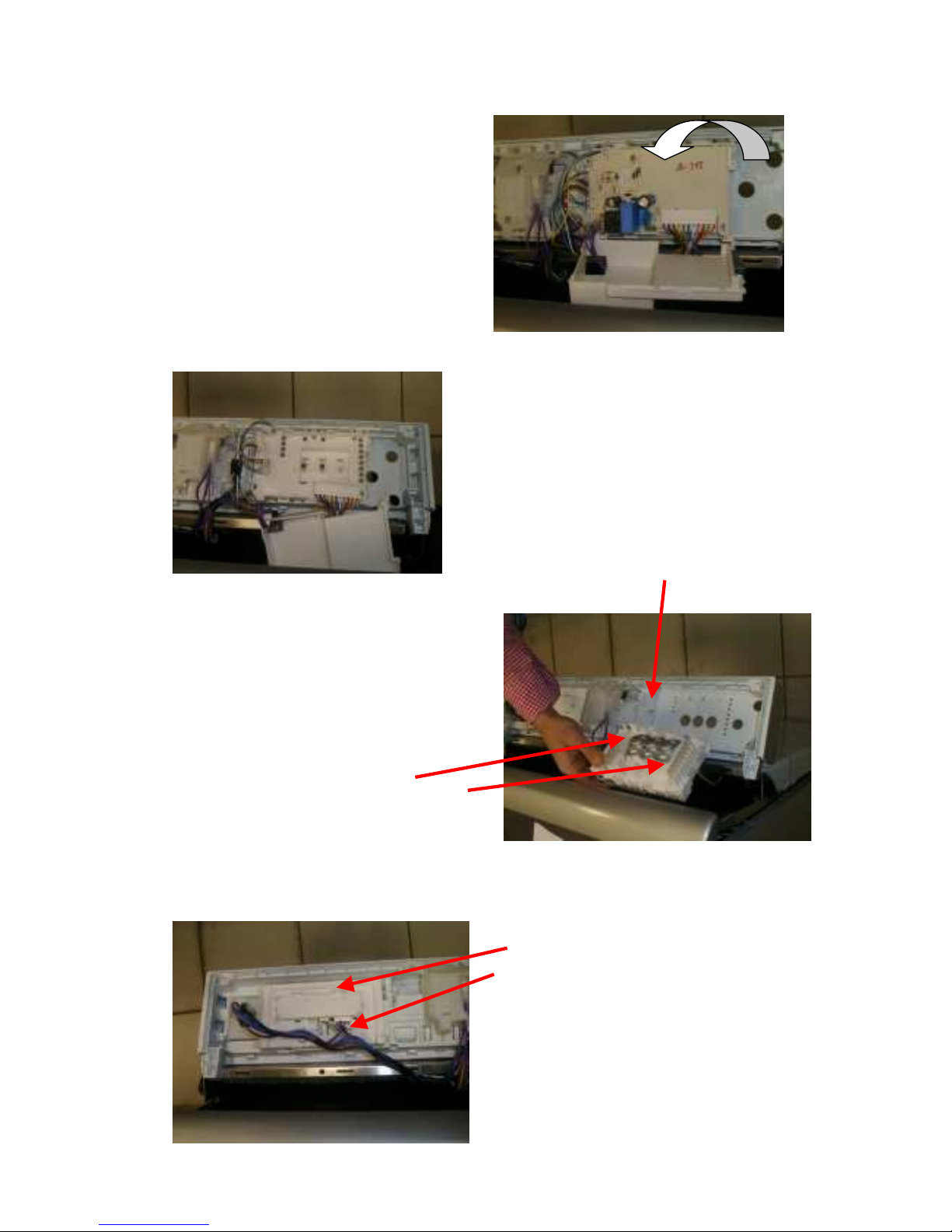
6) DISPLAY GROUP
Release the 3 snap fits in
order to open the cover of
the card holder.
In order to dismantle the
main card pull out the
sockets assembled to the
card.Then bend the snap fits
and pull out the main card.
A
s the main card is removed
the leds are easily
dismantled.
Main card holder is
dismantled by bending the
snap fits located on the panel
back structure.
The program select,
start/stop and the ½ load
key caps then easily be
dismantled.
For the models that have a
display, display board holder
can be disassembled by
releasing the snap fits
similiar to the main board
holder. Then display
electronics can then be taken
out in the similiar manner.
Page 4
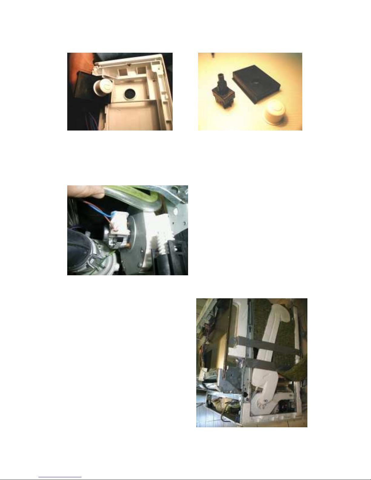
7) ON-OFF BUTTON KEY HOLDER
The key holder is fixed to the panel back structure by snap fits. The key cap
should be mounted before the holder assembled to the panel back structure
8) FAN GROUP
The Fan motor is located
under the contsruction and
over the heater.
The fan motor is assembled
to the holder and air funnel
by using screw. Fan
propeller is located inside the
air funnel and assembled to
the fan motor shaft by the
help of a snap fit.
The air discharge way is
located at the right side of
the machine.
Page 5
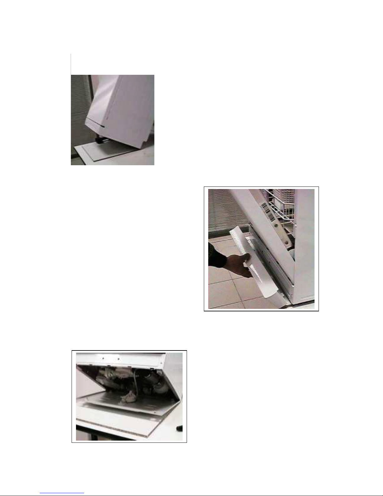
9) BOTTOM TRAY
While providing service to the components
located beneath the machine, the machine is
moved to a place other than the place of
installation.
For dismantling the tray, the machine is inclined
backwards with an angle of approximately 40˚.
2 screws holding the base and located
on the front side are removed and the
components beneath the machine are
accessed. Thus, it is possible to work
on all the components except for the
Water Inlet Valve, Clip Holder and the
Drain Hose.
The door is swiftly opened and the
plastic cover located at the bottom of
the machine is taken out, by being
rotated in the downward direction
without using any tool. Afterwards
when this plastic cover is repositioned,
the similar procedure is applied but this
time by being rotated in the reverse
direction
Page 6
10) OVERFLOW GAUGE
The mechanism attaching the
overflow gauge to the base is
pulled to the front direction, by
pressing the latches and then is
taken out.
11) DRAIN PUMP
The notch is opened and turned in the counter clockwise direction and taken
out by rotating it 10-15˚.
12) NTC
NTC is taken out by being rotated
30˚.
Page 7

13) HEATER
Pipe type heater is used in the machine. It is taken out by unscrewing the two
spring clamps.
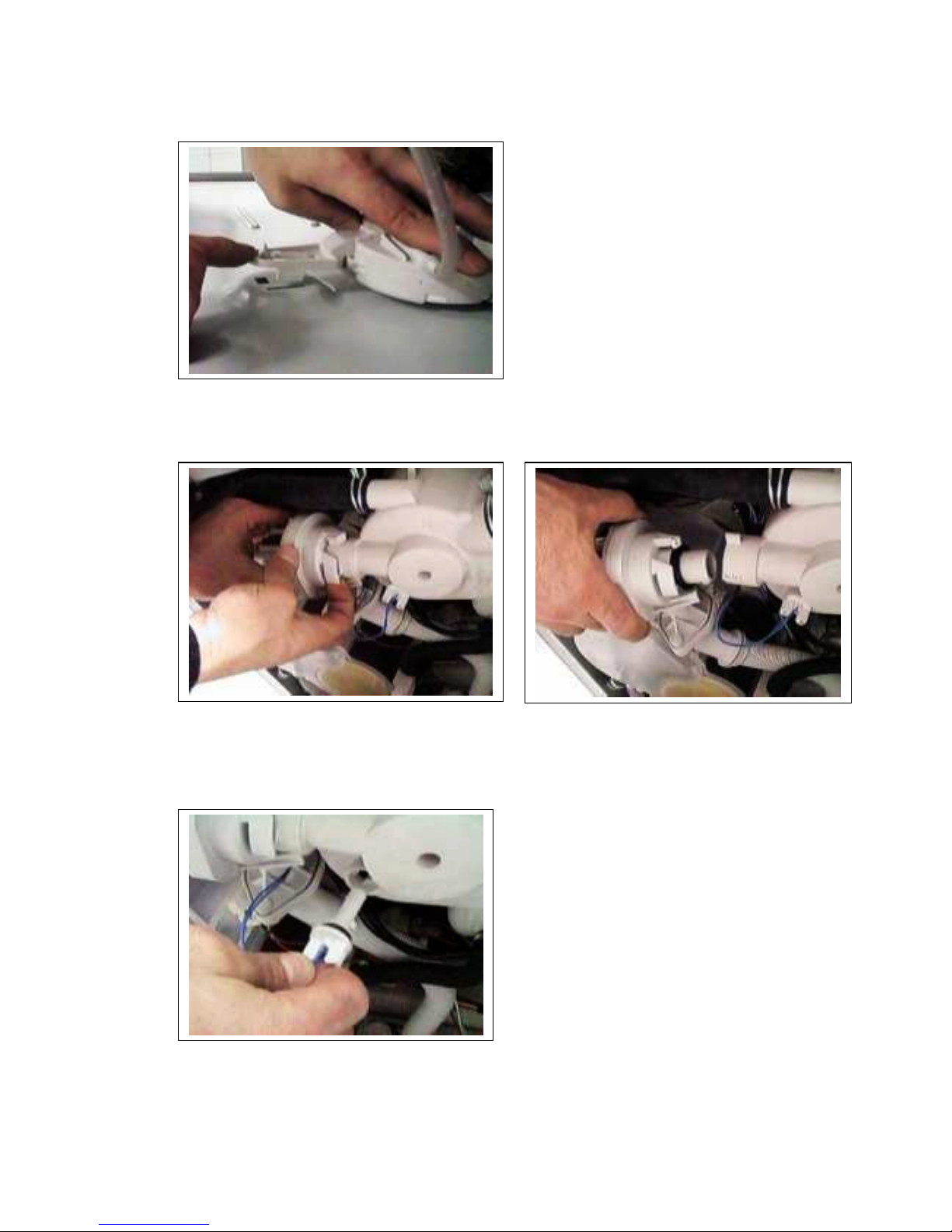
14) CIRCULATION PUMP
After the clamps and cable
connections of the circulation pump
are removed, the screws of the motor
holding plate connected to the body
frame are unscrewed. So as to detach
the circulation pump from the motor
holding plate, the connection is cut off
by breaking the white coloured auricle
shown in the photo, and a new auricle
is installed during the assembly.
Page 8

15) FEEDING PIPE OF THE UPPER SPRAY ARM AND FILTER
SUPPORT
Filter support is freed after the related screw is loosened. After the notch of
the feeding pipe of the upper spray arm is released, both of the parts are
taken out. After the notch located on the filter support is extended, it is
removed from the upper feeding pipe.
16) SIDE WALLS
A total of 7 screws, as 3 in the front, 2 at the back and 2 at the top, are
loosened and the side walls are taken out.
Page 9

17) REGENERATION CONTAINER
The 2 metal notches are released through a
screwdriver. The lid of the regeneration container is taken out by being rotated
in the counter clockwise direction at 5-10˚.
18) FLOW-METER
The electronic counter on the flowmeter located at the left lower corner of the
regeneration container, is taken out as demonstrated in the photo and
detached from the socket.
Page 10

19) HINGE PLATES
3 screws on the both sides are loosened.
2 screws on the both sides of the
connection sheet of the hinge arm are
unscrewed and the plates are removed.
20) DETERGENT CONTAINER
The inner door plate, held by 8
notches, is taken out by releasing the
lobes.
Page 11

21) CABLE CASE
To replace any cable, the cable case is
opened and the replacement is made.
22) CONCRETE SHEET
Both of the sidewalls are dismantled. A total of 4 screws connecting the
concrete sheet to the frames from both sides are unscrewed. 2 screws that
connect the base to the concrete sheet are unscrewed. Water inlet hose is
taken out. Base is dismantled. The connection made to prevent the
occurrence of siphonage in the drain hose is removed by cutting the hose
clamp. The concrete is taken out and the sheet is freed from its connections.
23) DRAIN HOSE, WATER INLET VALVE, and CLIP BOX
Page 12

To render services to these components, the operators should work on the
backside of the machine. The concrete sheet should be removed.
The hose holder is taken out by turning as it is seen in the picture.
The drain hose holder is made up two symmetric parts, which fit together by
the help of the snaps, and should be located approximately 30 cm from the
hose end.
For disassembling the water inlet valve, the screw of the water inlet valve
located on the concrete sheet is unscrewed.
Water inlet valve is taken out by being rotated in the clockwise direction.
(according to the back of machine)
Page 13

For dismantling the interference filter and the main power cable first of all
dismantle the sockets. Unscrew the screw mounted on the main power cable
holder and release the cable.
Then unscrew the two screws, assembling the interference filter and the
concrete sheet. Push the filter as it is seen in the picture in order to release it.
24) THREE WAY VALVE
Unscrew four screws, after loosen the hose clamps disassemble the valve
Page 14

25) FOOTS
The notch in the middle is pressed by a screwdriver.
26) UPPER SPRAY ARM
First follow the instructions given for the top plate. After disassembling the top
plate, loosen the nut by turning to counter clockwise direction. Press the
snaps of upper spray arm group & pull down for dismantling
Page 15

BOTTOM LAYOUT
The inner tub differs because of the change made fo
r
the new sump, and sump connections .
Sump o-ring is placed between the sump
and the inner tub in order to preven
t
leakage
New filter support part is fixed to the sump
and inner tub by the screws numbered as 3,
4 and 5.
Sump
Gasket
1
2
3
4
The sump is fixed
to the inner tub by
the help of 5 PT
type screws as
shown in the
picture left.
5
Drain pump group should be fixed to the sump by the help of snap fits.
The drain hose is assembled to the
drain exit of the sump by using a
hose clamp
Page 16

The flow diverter is assembled to the sump by hot plate, for the DW models that have
flow diverter. This is default for factory outlet, and no serviceability for the flow
diverter alone.
3W valve should be fixed to the sump by PT
screws, for the DW models that have 3 wa
y
valve.
Motor bracket for the new bottom layout is also
changed but has no difference in the assembl
y
manner
The new filtering system is changed
because of better performance and because
of sump change. But has no difference in
the assembly manner.
For the models having
metal filter, metal filter
o-ring is used. The
assembly of the part is
shown on the pictures.
Page 17

The filtering system will be
effective if the assembly of the
filters are done in the righ
t
manner. For both the metal
and plastic filter, the filter ends
should be positioned under the
related region of the flo
w
diverter.
 Loading...