

Eurolux DW9-CBE7, DW12-CBE7 User Manual
Code: 012050
Dishwasher
DW9-CBE7
Instructions for Use

1
Index
en
Safety i n fo r ma ti o n
Installation
Getting to know your dishwasher
How to fill the salt
How to fill rinse aid
How to fill the detergent
Not suitable for the dishwasher
Arranging crockery, glasses, etc. in the dishwasher
Programme overview
Washing dishes
How to keep your dishwasher in shape
Care and maintenance
Fault finding
Technical data
Important information
2
4
11
12
14
15
16
17
19
21
26
27
28
32
32

2
Safety information
en
The dishwasher must only be used by adults for the washing of household dishes and cooking utensils.
This appliance cannot be installed outdoor, not even if the area in which it is installed is covered by a
roof; it is also very dangerous to leave it exposed to the rain and elements.
Do not place any heavy objects or stand on the door when it is open. The appliance could tip forward.
The water inside the dishwasher is not suitable for drinking.
Do not use solvents of any kind inside your dishwasher. They could cause an explosion danger.
Open the door very carefully if the dishwasher is operating. There is a risk of water squirting out.
During normal use
Do not touch the heating element during or after a wash cycle.
Fundamental rules to follow when using the appliance:
- Never touch the dishwasher when barefoot or with wet hands or feet;
- We discourage the use of extension cords and multiple sockets;
- If the appli an c e is not op er ating p r operly o r m aintena nc e must be perf o r m ed, dis c onnect the
appliance from the power supply.
Place the dishwasher and connect it up in accordance with the installation instructions.
The dishwasher must not be connected to the electricity supply while installation is being carried out.
Ensure that the domestic wiring is properly earthed.
The mains electricity supply must conform to the details shown on the dishwasher nameplate.
Do not connect the dishwasher to the electricity supply via an extension cable.
Built-under and built-in appliances s hould alway s be installed under a continuous work s ur face whic h
is attached to the adjacent cupboards, in order to ensure that the appliance is entirely stable.
After the appliance has been installed,the mains plug should still be easily accessible.
The plastic hous ing on the water in let co ntains an electrically o pera ted va lve.The connecting wir es
are inside t he inle t hose.Do not cut thr ough t his hos e and do not im mer s e the plastic housing in water .
During installation, the power supply cord must not be excessively or dangerously bent or flattened.
During installation
For Switzerland only:
There are no restrictions on installing the appliance between wooden or plastic walls as part of a fitted
kitchen. If the appli ance is not plugged into a wal l soc ket, it mus t be connec ted to the m ains v ia a
separator for all poles within the domestic wiring system. This device must have a gap of at least 3mm
between open contacts, in order to conform with relevant safety regulations.
At time of delivery
Check packaging and dishwasher immediately for signs of transport damage. If the appliance is
damaged, do not put it into use but contact your supplier or customer service without delay.
Please dispose of packaging materials properly.
3
If your family in clud es children
This appliance is not intended for use by persons (including children) with reduced physical,sensory
or mental capcab ilities, or lack of experienc e and knowledge,unless they hav e bee n giv en su perv ision or instruction concerning use of the appliance by a person responsible for their safety.
Children should be supervised to ensure that they to not play with the appliance.
Keep detergents out of the reach of children, who m us t also be kept away from the dishwasher when
it is open.
If a fault occurs
If the appliance malfunctions, turn off water supply to the appliance and disconnect the plug from the
wall socket. Then, consult the section entitled, "Fault finding" . I f you cannot solve the problem, contact a service center.
Only specialised personnel are authorised to make repairs.
If the supply cord is damaged ,it mus t be replace d by the man uf acture ,its servic e agent of similarly
qualified persons in order to avoid a hazard.
To maintain the EFFICIENCY and SAFETY of this appliance,we recommend:
- call only the Service Centers authorized by the manufacturer.
- always use original Spare Parts.
When disposing of old appliances
Appliances whic h a r e no longer being used mus t be m ade inoperable by c ut ting the power s upply
cord and removing the door lock.
Take the appliance to a designated waste disposal center.
Warning
Children could get locked in the appliance (risk of suffocation)
or get stuck in other positions. Therefore: Remove the mains
plug, cut the mains wire and set aside. Damage the door lock so
that the door can no longer be closed.
Dangerous voltage
en
4
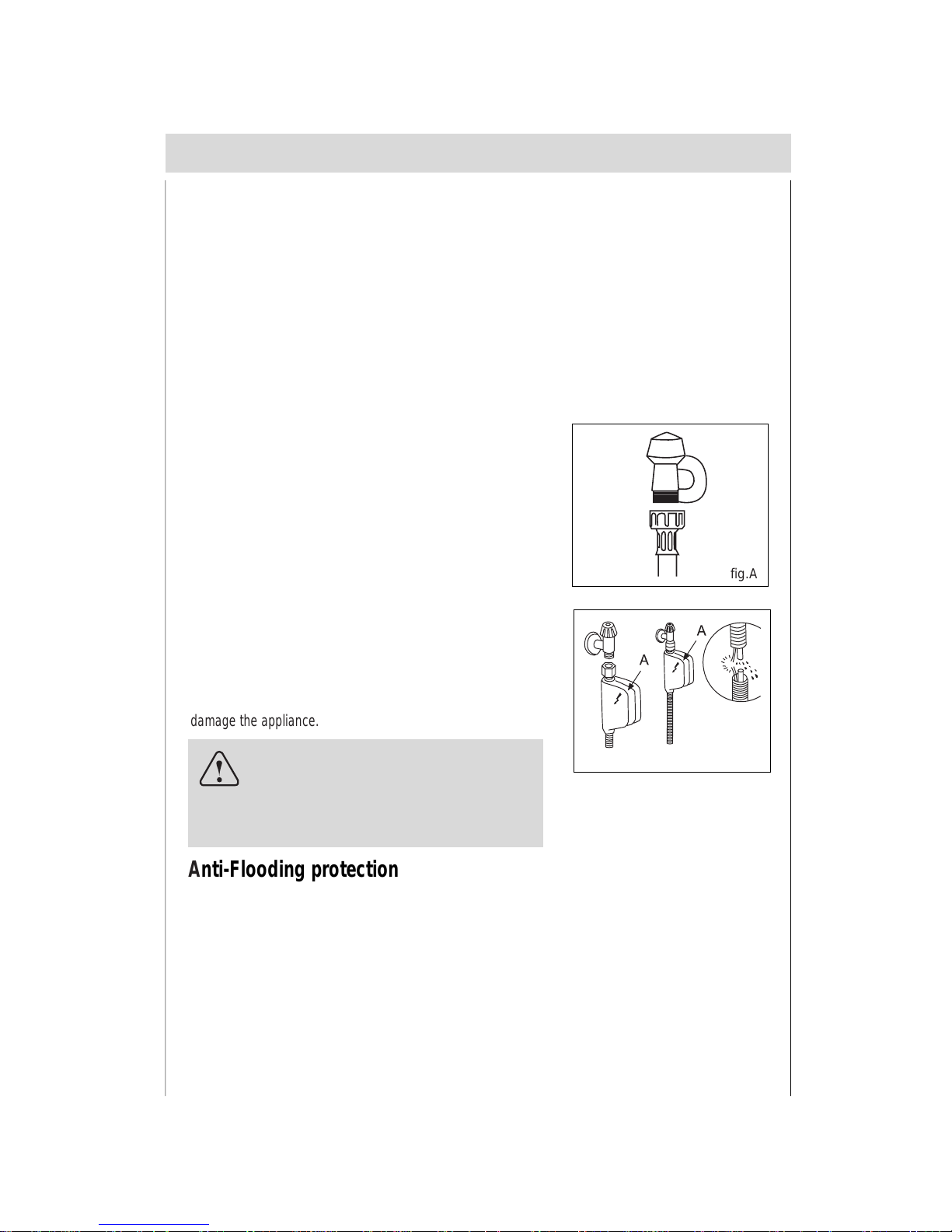
Cold wat er connectio n
Connect the water supp ly hose to a threaded 3/4 (gas)
connector, making sure that it is fastened tightly in place (see
fig.A).
Some models are fitted with an "Aquastop" wat er su pply hose
(see fig .B ) in w hic h the s mall filt er is alr eady hous ed in th e
threaded end.
If the water pipes are new or have not been us ed for an ex tended period of time, let the water run to make sure that the
water is c lear and fr ee of impur ities. If this prec aution is not
taken, there is a risk that t he water inlet can ge t blocke d and
damage the appliance.
Positioning the appliance
Change the ap plianc e in t he de sir ed lo cation. The back sho uld r est agains t the wall behind i t, and the
sides , alo ng the ad jac ent ca binet s or wal l. T he dis hwas her is e quipp ed wi th w ate r supp ly an d d rain
hoses that can be positioned to the right or the left to facilitate proper installation.
fig.A
Anti-Flooding protection
If dishwasher is equipped with a system that stops the supply of water in the event of a problem with the water
supply hose, or leaks within the unit, in order to prevent damage to your home. If for any reason the box
containing th e el ectric al com ponents happ ens to get da m aged, remove the pl ug f or th e app li ance from the
socket immediately. In order to guarantee that the anti-flooding feature operates properly, the "A" box with water
supply hose must be attached to the water supply tap as shown in fig.B. No other type of con nection is a cceptable.
The water supply hose must not, under any circumstances, be cut, as it contains electrical parts which are live.
If the length of the hose is not adequate to make a proper connection, the hose must be replaced with one which
is long enough. This hose is available upon request from specialised retailers and service center.
fig.B
Levelling the appliance
Once the appliance is positioned, adjust t he feet (screwing t hem
in or out) to adjus t the dishwasher, mak ing it level. In any ca se ,
the appliance should not be inclined more than 2˚. If the appliance is levelled, it will help ensure proper performance.
Installation
Warning
The appliance is to be connected to the
water mains using new hose-sets and
that old hose-sets should not be reused.
en
5
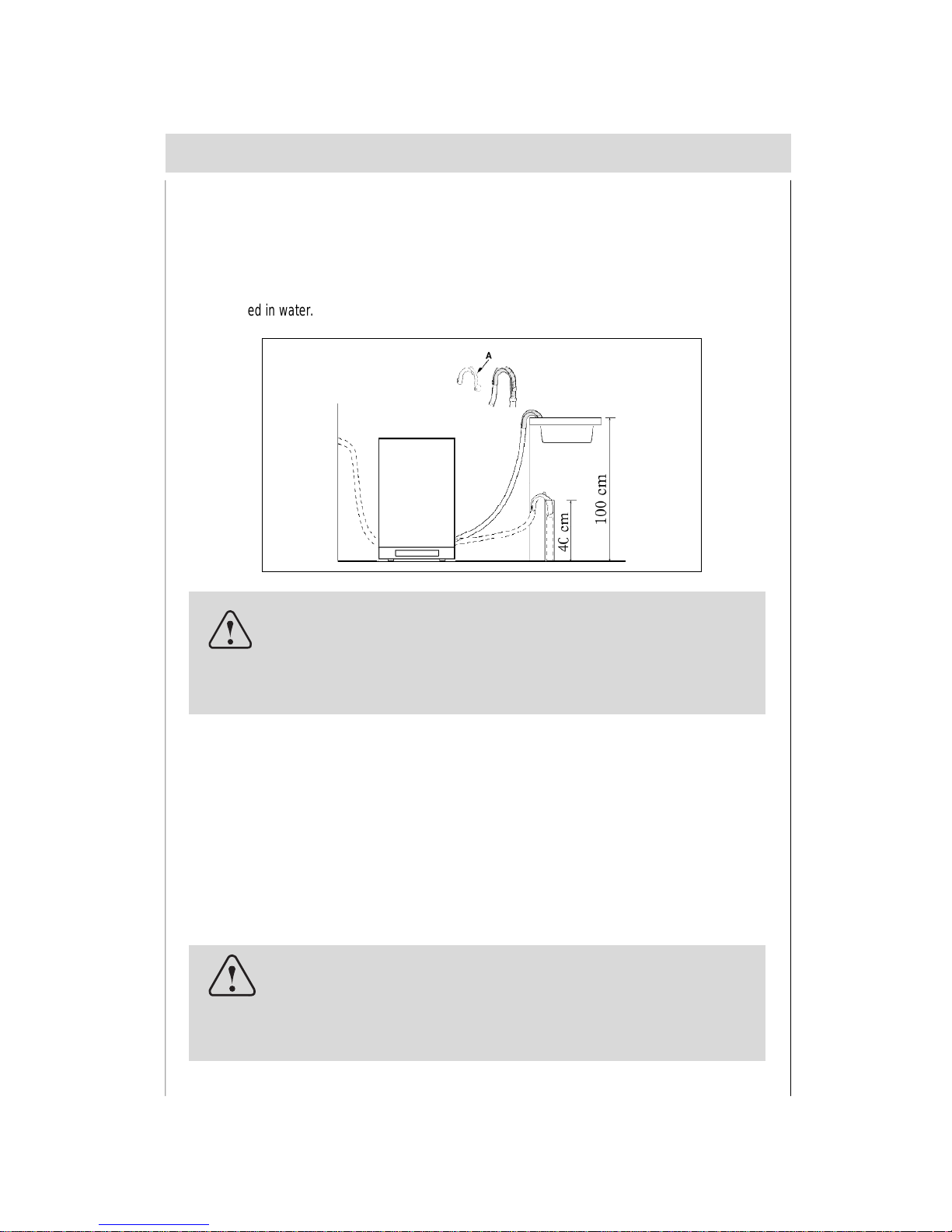
Drain hose co nnect ion
Insert the drain hose into a drain pipe with a minimum diameter of 4cm , or let it run into the sink, making
sure to avoid bending or crimping it. If necessary, fit a syphon trap (U-bend) with a connecting piece for
the drain hos e ( fig.C) . The free end of the hose m us t be at a height between 40 and 100 cm and mus t not
be immers ed in wa t er.
fig.C
Attention:
The connecting piece for syphon trap (U-bend) must be solidly
fastened to the wall to prevent the drain hose from moving and
allowing water to spill outside the drain.
Electrical Connection
After making sure that the voltage and frequenc y v alues for the c ur r ent in the home cor r esp ond to those
on the r ating plat e (locat ed on the st ainles s st eel inner door of the ap pli ance) and that the elec tric al
system is correc t for the maximum voltage on the rating pl at e, inse rt t he p lug int o an electrical sock et
which is earthed properly (the earthing of the appliance is a safety requirement mandated by law).
If the electrical socket to which the appliance must be connected is not appropriate for the plug, replace
the who le cab le, rathe r than using ad aptor s or the sim ilar lik e as the y c ould c ause o ver heatin g an d
burns.
Caution:
The dishwasher plug must be accessible even when the appliance is installed as a built-in unit so that maintenance can be
done safely.
en
Supplied with the appliance is a plastic (self adhesive)
anticon dens ation str ip, this should be fixed to t he under side of
your worktop along the front edge. The adjustable feet of the ap-
pliance allow it to be r aised up t o 870 mm, i f the spac e between
the floor and the under side of the work sur face is greater tha n
870mm, then the appliance should be positioned on suitable
Stage 1
Installatio n cont ..
fig 1a
wooden spacers whi ch should always be fixed to the floor. A lway s us e a spir it level to make s ur e that the
appliance is level left to right and front to back.(If the appliance is installed on a carpet, ensure there is
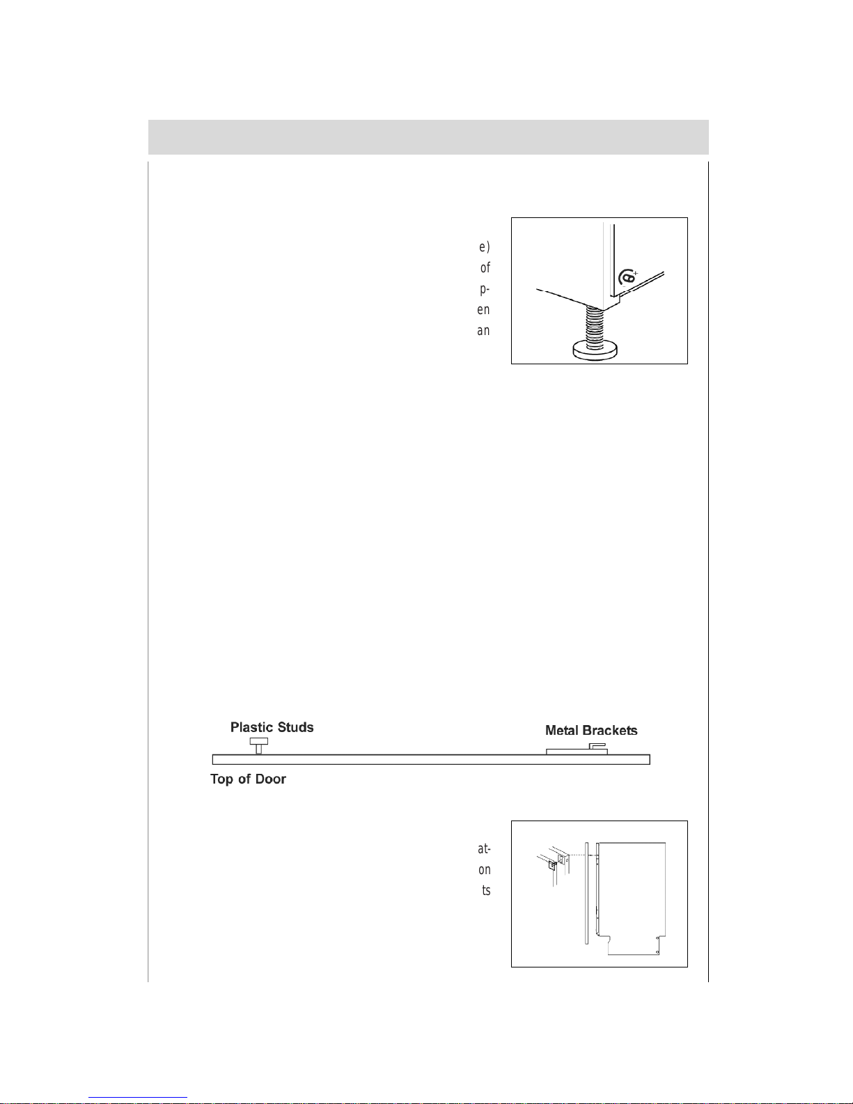
clearance beneath the appliance). The four adjustable feet should be adjusted to the correct height; the
rear feet are adjustable via studs at the front of the appliance (fig 1a).
To prevent damage to the floor covering, the a ppl iance mus t be install ed using the plas tic skids p r ov ided.
Stage 2
Connect the wat er , drain and electrical supplies (220V~240V, 50Hz) . We recommend that the appliance
is connected to a cold water supply.
Measure the width of the decor door.Align the template on the rear of the door with the top of the door
level with the top of the templa te, and t he l eft hand edge of the door in line with the measured door width.
Mark the four fixing poisitions. Repeat on the right hand side. Remove the template, and drill pilot holes
in the door in all eight positions using a suitable drill (take care not to drill through the door). Attach the
upper plastic studs and lower fixing brackets to the decor door as shown below.
Stage 3
Position the decor door onto the front of the dishwasher by locat-
ing the brackets into the two plastic studs m ounted either side on
the top of the doo r. Lift the decor door until t he low er br ack ets
locate into the slots in the appliance door.
Stage 4
6
en
Align the top of the decor door with adjacent cabinets. Gently
open door whilst supporting the decor door. Once in the lowered
position, secure the decor door using t he fixing screws provided
as shown in the diagram. Cover the screw heads using the plas-
tic caps provided.
Stage 5
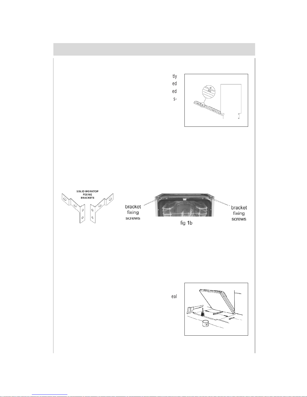
The dishwasher should now be screwed t o the under side of t he wor ktop, via the t wo fixin g holes in t he
top trim.
For non-wooden worktops (e.g. marble) two brackets are provided to allow the appliance to be secured
to the sides of the adjacent cabinets. The should be secur ed to the appliance using the two screws at the
top of t he cha ssis (s ee fig 1b) , adj usted to th e cor rect width an d th en sc rewe d to th e adja cent sid es
panels using suitable screws.
Stage 6
The door bala nce can be adus ted via t wo screws accessed thr ough two hol es in the top of the front
frame. Adjust these until the door just remains open under its own weight and is level when open.
Stage 7
Cut clearance in t he pli nth to allow t he door to open fully and s eal
edges with a suitable varnish to prevent water ingress.
Stage 8
7
en
Assemb ly Inst ructio ns for Integr ated Dishwasher
Mounting the Wooden Panel onto the Door and Sliding the Dishwasher into
the Cabinet
During the preparatory stages for installing the dis hwas her into the kitchen cabinet, holes m ust not be
drilled in the sides, or door , in order t o av oid compro mis ing the per f ormance an d/ or oper ation of the
appliance. Before working on any internal components, the unit must be disconnected from the power
supply .The maximum dime nsions for the wood panel that can be installed on the door are: Hei ght 725 mm for the completely built-in version; Width - 448 mm; Thickness-20 mm.
The height dimension of 725 mm must be reduced if the height of the control panel is increased
through the use of the spacers. In addition, the base must be trimmed if it interferes with the opening
of the door.
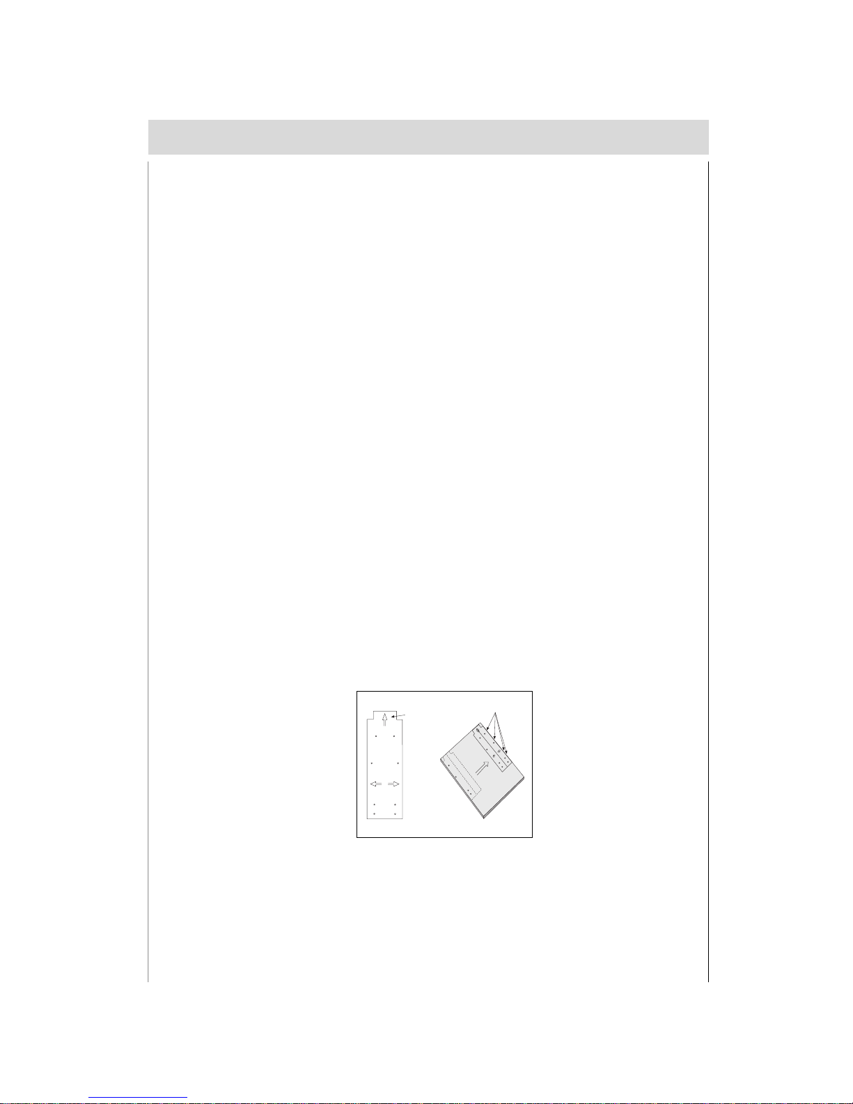
Align the top edge of the t empl ate ( ident ified with the “A ” arrow ) with the top edge of the panel. On
both sides of the template (top and bottom ) are written the various dimensions that correspond to the
differ ent pos sibl e wid ths f or the pa ne l. Al ign t he te mpla te w ith the s ide o f t he p anel ( lef t or righ t),
making sure that the panel coincide s with the appropriate dim ens ions. M ark the posit ions for the holes
for the screws, using the tip of a drill or a pencil. Th e three holes clos es t to the side sh ould be used (B).
Repeat this step on the other side of the panel ,using the corresponding side of the template.
Using the Drilling Template
8
en
A
B
Fig.1
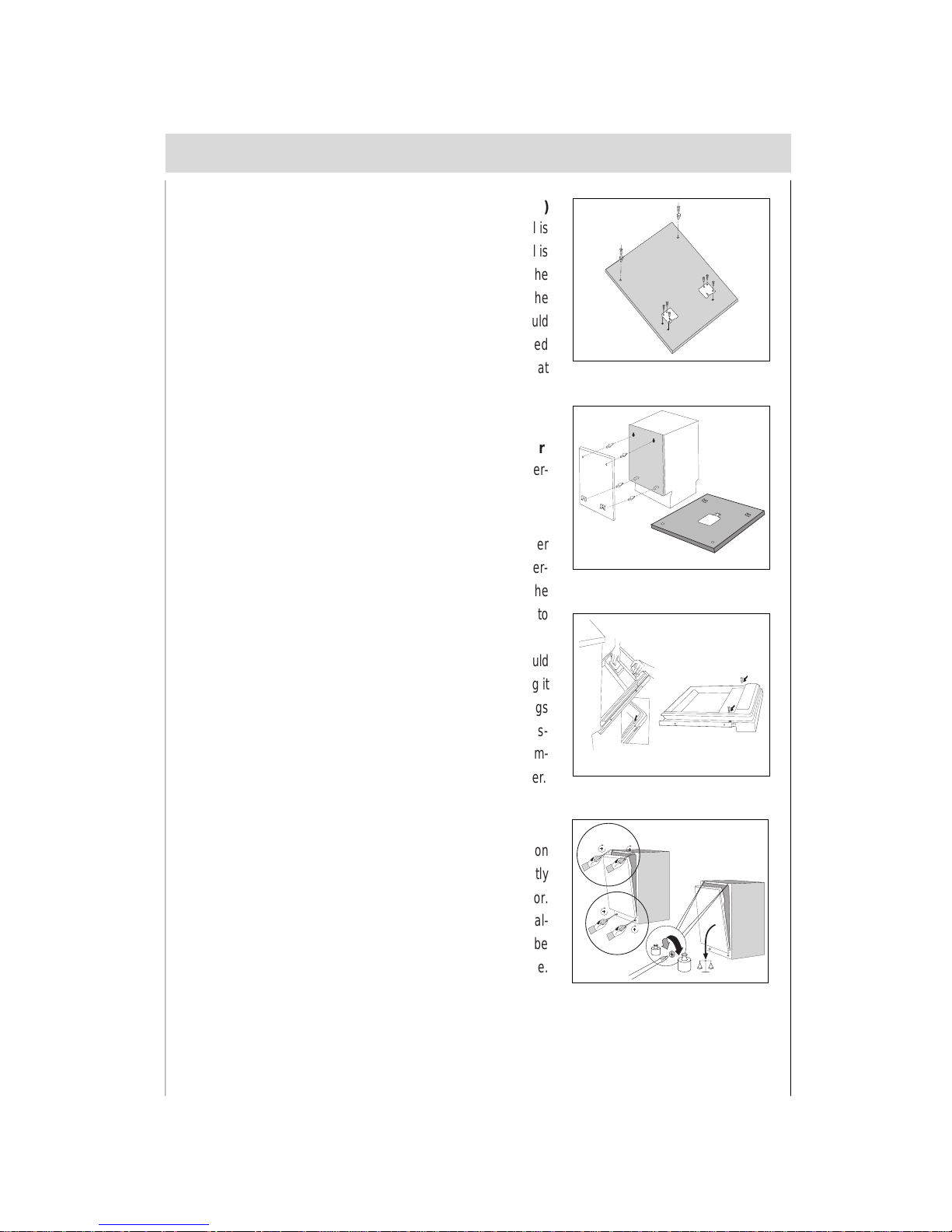
At the point marked, drill holes 2 mm in diameter . If the panel is
made of chip board , only drill through the veneer. If the panel is
made of solid wood, the holes can be made deeper. Position the
two brackets so that they are lined up with the holes m ade in the
bottom part of the panel. The holes furthest to the outside should
be used to fasten the brackets. The small f ins should be t urned
downward. The hook s s hould be s crewed int o the t wo holes at
the top.
Fastening the Bracket to the Wooden Panel (Fig.2 )
Place the wood panel onto the door of the dishwasher. Then per-
form the installation steps described below,
Mounting the Wood Door Panel onto the Dishwasher
Insert the top hooks into t he appropriat e slots in the dis hwasher
control panel. Then push t he panel upwards until it stops. After-
wards , s lide the panel down w ard again, moving t he bottom of the
panel toward the door so that the fins on the brackets slide into
their slots (Fig.3).
In both cases, open the doo rs of the dishwasher (the pa nel should
stay in place by itself) and ali gn the panel w ith the door, keeping it
in contact with the control panel. Remove the small plastic plugs
that cover the hole s on the inside of the dishwa sher door and fas-
ten the panel in place with the screws provided (Fig. 4). Remem-
ber to cover the two holes with the plastic plugs removed earlier.
The door must be perfectly balanced. In the factory , the tension
of the springs is regulated to ensure that the door is perfectly
balanced when light wood door panels are mounted on the door.
If heavier, solid wood door panels are used, the door can be bal-
anced b y s impl y tur ning th e tw o scr ews (bot h s crews mu st be
turned the same amount) located on the top part of the machine.
Adjusting the Door Springs (Fig.5B)
9
en
2-7Kg
Fig.3
A
B
2Kg
7Kg
Fig.5
Fig.4
Fig.2
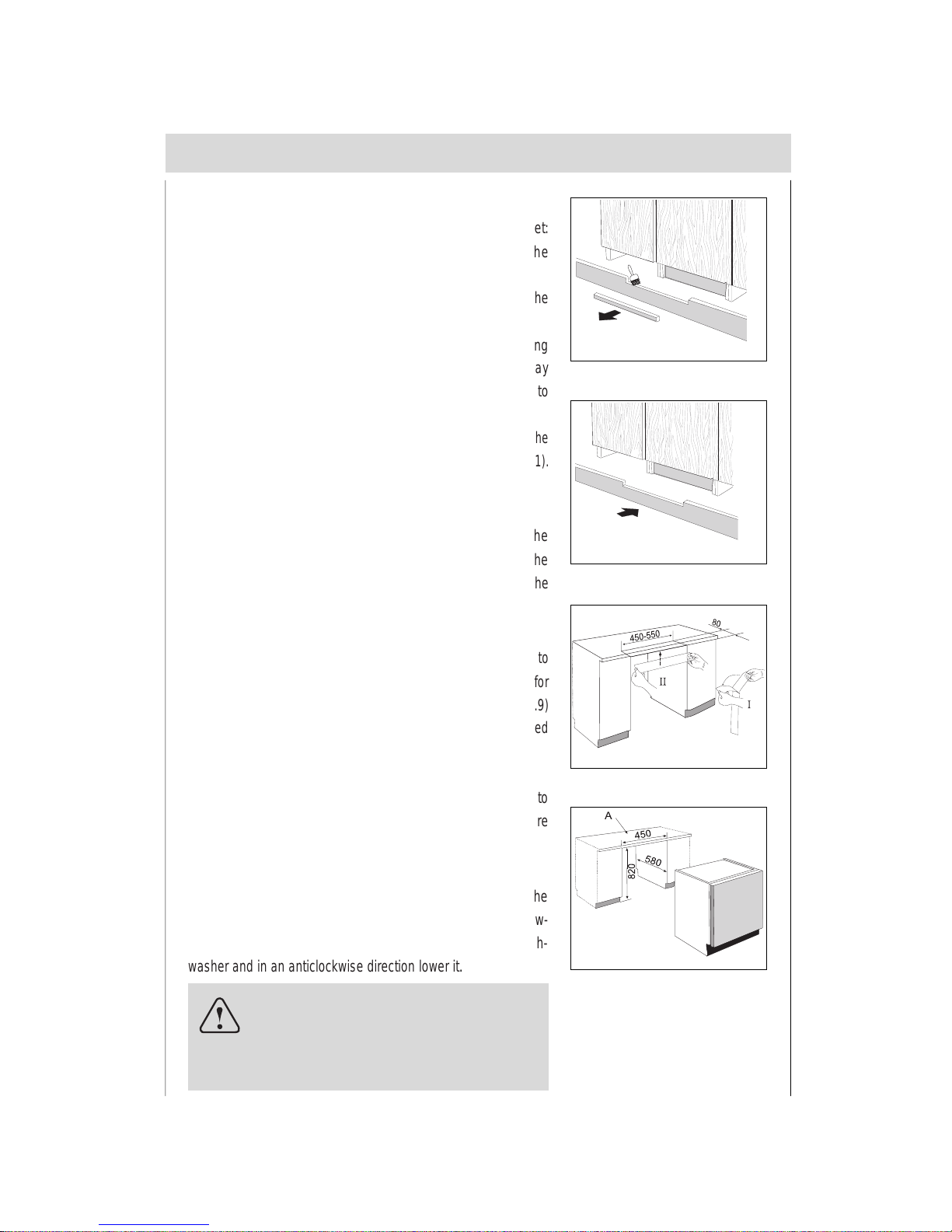
Installation of Continuous Base Moulding
Position t he w as hing machi n e i n the cut-out in the kit chen c a bi n et :
1. Install the continuous base moulding , following the
manufacturer’s instructions .
2. Slowly open the door of the dishwasher to check to see if the
door strikes or rubs against the base moulding.
3. If so, rest the bottom edge of t he panel on the bas e mou lding
and mark the part to be cut. Leave at least 3 mm of the play
between the panel and the base moulding to allow for the door to
rotate freely (Fig.6).
4.
Remove the base moul ding and trim it as needed, protecting the
surface that has been cut with a paint or similar wood finish (Fig.11).
5. Install the base moulding again (Fig.7).
Positioning the Unit within the Cutout (Fig.9)
Push the dishwasher into the cutout opening and turn the feet to
make it level and to adjust for heigh t so that the crosspie ce (A) for
fasteni ng it in pla c e loca ted on the to p part of the mach ine (Fig.9 )
comes into contact with the counter .Align the door panel mounted
on the dishwasher with the doors on the adjacent cabinet (2).
Important:
The dishwashe r m us t absolutely be fastened to the counter t op to
prevent the machine from tipping when the loaded dish racks are
pulled out.
How to use water-proof plastic
First ly tak e off the wat er -proof plas tic fr om t he s tick er with th e
appliance ( s ee ¢æ, Fig.8). Sec ondly s t ick it on the bottom of t he
kitchen board (see ¢ , Fig.8). All of this can avoid humidity in the
kitchen.
Adjustment of Back Feet (Fig.5A)
Insert the appliance in the cutout and then adj ust the heig ht of t he
machine using the screws located at the bottom f ront . Use a screw-
driver to t ur n the scr ews in a cl ock wis e di rection t o rais e the dish-
washer and in an anticlockwise direction lower it.
NOTICE:
If power screwdrivers are used to make the
adjust ment, make t he final adj us tment manually wit h
a normal sc re wd river.
10
en
Fig.6
Fig.7
Fig.8
Fig.9
 Loading...