

Eurolube Equipment 15715 Service Manual
10:1 HV AIR OPERATED OIL PUMP
0
0 7.6
(2)
15.1
(4)
22.7
(6)
30.3
(8)
37.9
(10)
45.4
(12)53(14)
60.6
(16)
13.7
(200)
27.6
(400)
41.4
(600)
55.1
(800)
68.9
(1000)
82.7
(1200)
96.5
(1400)
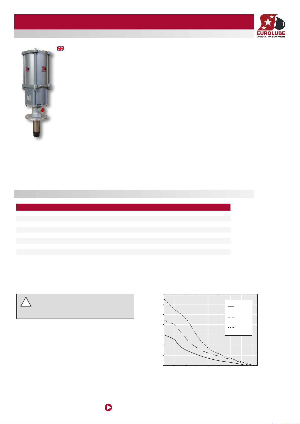
Pump Pressure/Flow
Test fl uid: 10W30 Oil
Fluid Pressure, bar (psi)
Flow, l/min (GPM)
5 bar
(70 psi)
7 bar
(100 psi)
10 bar
(150 psi)
PART NO 15715
General
Thank yo u for choosing a high quality pump from Eu rolube Equipment AB Swe den. The 10:1 oil pu mp featu res an unique air
motor for q uiet an d quick servi ceability. Recomme nded fo r heavy duty un its and l arge pipe inst allations. Pl ease re fer to the s ales
catalogue for detail s on accessor ies. O r visit our websi te, ww w.eurolube.com.
The pump is suitable for s imult aneou s fluid distribution to multipl e dispe nse poi nts, or for pumping to distance s of up to 90 m
(30 0 ft) .
The air motor features a precision air va lve mechanism with dua l valve ports fo r improve d high sp eed br eathing. It als o conta ins a
positi ve trip de tent spool mec hanis m that eli minate s stalling (b lowing a ir) by preventing t he pump f rom stop ping be tween strokes.
It has a sim ple yet du rable construction with all internal par ts lub ricated at the fa ctor y using a life-te sted syn thetic grease.
The pumping as sembl y features a sta inles s pump ro d for superior wear and c orrosion resista nce. Th e pump’s exte rior is
constructed from aircraf t grade extru ded alu minum for an outstanding stre ngth and relia bilit y. The pump a lso has h igh qua lity
seals a nd is des igned f or long -term du rabil ity and ease of s ervice. The pump is also equipped with internal pr essure relie f to
protec t the system from therma l expansion.
A pump’s ability to deliver grease is b ased on the pressure ( bar/psi) a nd quan tity of a ir supp lied to th e air- motor a nd the am ount of
materi al disc harge ( back ) pres sure to be overcom e within the syste m.
WARNING! Do NOT use so lvent s or othe r explo sive flu ids. A n explo sion can res ult in th e pump wh en alumini um and z ink pa rts
come in c ontac ts with c ertain solvents . Never p oint a co ntrol valve at a ny por tion of yo ur bod y or anot her pe rson . Accid entia l
disch arge o f pres sure a nd/ or mate rial can re sult in injur y. Read t hese i nstruction c aref ully b efore i nsta llati on, ope ration or ser vice.
DO NOT EXCEED MAXIUMUM PRESSURE
2012-08 ORIGINAL MANUAL
SERVICE GUIDE
TECHNICAL DATA / TEKNISKA DATA
PART NO 15715
Pump ratio 10:1
Maxim um air pr essure 10bar (150ps i)
Recommende d air pre ssure 2,75-8,6b ar (40 -125 psi)
Minimum air pre ssure 0,7bar (10 psi)
Air motor effective piston dia meter 107mm (4,2” )
Nomina l pump st roke len gth 81,3mm (3, 25”)
Pump cycles per li ter (gallon ) @ 7 bar air pressure 105 cpl (28 c pg)
Fluid stall pre ssure @ 10 ba r air pre ssure 110bar (1300 psi)
Approx a ir cons umption @ 7 bar air press ure, 15l/min 1300 l/min (46 SCFM)
Operating Noise Level
85 DbA @ 7 bar (100 psi) air and 11l/min (3 GPM)
NOTE: This pump has been tested and found conforming to OSHA operating noise limits when used for
!
intended purpose (oil or coolant dispensing, intermittent duty cycles).
www.eurolube.com
1
EUROLUB E EQUIPMENT AB
www.eurolube.com
EUROLUB E EQUIPMENT AB
PART NO 15715
10:1 HV AIR OPERATED OIL PUMP
2
www.eurolube.com
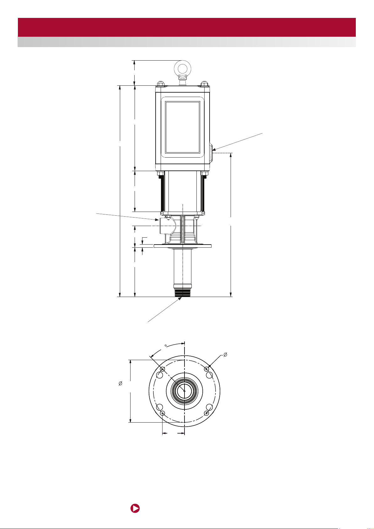
Ø 155.6
hole circle
45°
2.17
Ø 11.5
4 places
equally spaced
78
3/4" NPT(F)
Fluid Outlet
Port
654
264
127
67
152
1/2" NPT(F)
Air Inlet Port
292
91
1" NPT(F)
Fluid Inlet Port
45
11.5
4 places
equally spaced
155.5
hole circle
55
TYP
Figure 12
Complete Pump
Dimensions & Features

www.eurolube.com
EUROLUB E EQUIPMENT AB
PART NO 15715
10:1 HV AIR OPERATED OIL PUMP
3
PUMP INSTALLATION
WARNING: Attach a proper ground wire to
the pump grounding lug (item 52, p.10) before
!
starting the pump.
NOTE: Pump performance will be degraded
by air or uid threaded connections which are
!
not air-tight. Use Teon™ tape or other suitable
means to achieve a complete thread seal.
PUMP OPERATION
CAUTION: Read all limitations which apply
to selection of uids which may be pumped by
!
this product. Do not pump a uid which is not
specied to be compatible.
CAUTION: Always read and follow fluid
manufacturers' recommendations regarding
!
proper use of protective eye wear, clothing
and respirators.
Provide a d rop-te e fitting, 3/4” size or lar ger, in the ne arby ai r suppl y pipeline. From that tee, install the following pump air line assembly:
pipe bushing or a dapter (to bring the line drop size to 3/4” male)•
1/2” pip e drop to pu mp level•
1/2” pip e elbow•
1/2” air F-R-L•
1/2” air s hutof f ball valve (having an air relief vent when close d)•
1/2” to 3/8” reducer a nd a 3/ 8” x 3 ft. a ir hose•
3/8” air line c ouple r and nip ple.•
Attach the air nipple to the air inlet port of the pump. During assembly of the air supply line, be sure to clean out all foreign materials
before making connection to the pump. Eurolube recommends that an air line lubricator be used with turbine oil (viscosity 150-170 SSU @
37°F) and set at a maximum oil feed rate of 1 drop every 2 hours of pump operatio n. The pump air motor has been coated internally with a
special synthetic grease at initial as sembly and does not require additional grease except during rea ssembly af ter a repair.
TO START PUMP:
Immer se the pump’s suctio n tube or fl uid inlet into the fl uid to be pu mped.1.
Connect the air coupler to the pump and turn the air regulator to the minimum s etting.2.
Direc t pump ou tlet hose into an approved waste oil c ontainer.3.
Slowly adjust th e air reg ulator until the p ump is pr imed and running smoothly. Be sure all air h as bee n purge d from th e 4.
system. T he pump s hould p rime in less tha n 30 sec onds.
Use the ai r regul ator to control th e pump’s spe ed and cycle rate. Always use the lowe st pres sure re quire d to obtain the 5.
desired flow rate. This will incre ase pump and se al life.
Never all ow a pump to be run dr y of the fluid being pumped. A dry pump quic kly speeds up, w hich co uld dam age the 6.
air motor and fluid seals. If the pum p sudde nly spe eds up, cut off th e air sup ply as so on as possibl e, refill the system
fluid res ervo ir and re prime t he pump.
If the pump will be un atten ded for a ny peri od of time, or to shut off the system at the end of a work shif t, always follow 7.
the Pres sure Re lief Pro cedure on page 5 of this manual.
If the pump will be un atten ded for a ny peri od of time, or to shut off the system at the end of a work shif t, always relieve 8.
the pump’s pressur e.
PUMP REPAIR / SERVICING
PUMP DISASSEMBLY PROCEDURE:
FIGUR E 11
Mount the pump horizont ally in a bench vi se. Clamp the vis e to the upp er body of the 1.
pump and use ela stic jaw c ushio ns in the vi se to preve nt scarring the pump surface.
With a socket wrench, loo sen and remove the four lowe r 5/16” Hex Bo lts [14] and Lock
Washer s [12]. Then remove and set aside th e Bare Lower suba ssembly. Also re move
the Lower B ody [4 ], Muffler [17], and Diffuser Plate [16] .
If the air motor subassembly will not be repaired immediately, re-atta ch the Lower 2.
Body [4 ], Mu ffler [7] , and Diffuser Plate [16 ] to the Air Motor subasse mbly, temporari ly
secur ing them with the 5 /16” Bolts [14] and Lock Washer s [12], tu rned hand tigh t.
Remove the assembly from the vis e.
For fur ther di sassembly, use t he sepa rate procedu res whi ch follow for the Air Motor 3.
and Lower Pump subassemblies.
AIR MOTOR DISASSEMBLY PROCEDURE :
FIGUR E 5
If the Lower Body [4 ], Muffler [17], and D iffu ser Plate [16] are attached to the A ir Motor 4.
subassembl y, remove them now, along with the four 5/16” Hex Bolts [14] and Lock
washer s [12] whic h secure them.
Mount the Air Moto r horizontall y in a bench vise. C lamp the vise to the Upper Body 5.
[2] of t he pump a nd use el astic j aw cushi ons in the vise to pr event sc arring the pum p
surface.
Using a so cket wre nch, hold the 1/2” Hex Acorn Nut [11] on the pu mp Cap [1] . With a 6.
secon d socket w rench, loose n and remove the 1/2” Hex Nut [10 ] and Lo ck washer [9 ]
at the other end of the 1/2”-13 Thread ed Stud [ 7]. Then re move the Ac orn Nut [11] and
Stud [7 ] as a group. Do not re move the Acorn Nu t from the Threa ded Stu d. Repe at the
proce dure for the other three Studs. Set aside all fastener s in a group.
Remove the Center Inser t [3 ] from the subassemb ly by slid ing it ca refully off the Air 7.
Piston. Remove the t wo O-r ing Seals, [ 5] and [26], fro m their glands on the Center
Inser t [3 ]. Set these part s aside i n a group.
Remove the Cap [1] fro m the top of th e Air Motor. As the Cap [1] is removed, it must b e 8.
shifted sideways appr oximately 1 inch to allow detachment from the internal Trip Ro d.
After removal of the Cap, remove the O -ring S eal [ 5] fro m the gla nd in the Ca p. Set
these parts a side in a g roup.
Remove the Air Moto r Subas sembly [shown in figu re 4] from the Upp er Body [2] . 9.
Remove towa rd the top of the pump, opposite the dir ectio n of the 1/2” NPT po rt on
the Uppe r Body. Slide out ca refully, keeping the Air Piston square with the bore of the
Upper Body. Remove the Uppe r body from the vise and se t aside.
FIGUR E 4
Remove the O-Ri ng Seal [6] from the A ir Piston [18]. U sing a flat blade screwdriver, 10.
remove two Detent Sleeves [29 ], De tent Springs [ 28] , and Detent Balls [27 ]. Se t all of
the removed par ts aside as a group.
Clamp th e Air Piston in a vise applied to the 6” piston diameter. Note! Use Split wood-11.
en vise blocks ma tched to t he pisto n diame ter to prevent sca rring the piston sur face !
Using two open-end wr enche s, loosen the Jam Nuts [ 25] lo cated o n top of the Intake 12 .
Valve Stems [22]. Rem ove the Jam N uts and the two Intake Valve Stems. It may be
neces sar y to secure the hex cap of the Valve Stem [22] with an open e nd wren ch while
removing the second nut. Then remove the O -Ring Seals [24] from the gl and of the
two Valve Ste ms [22].
Remove the Valve Trip Assembly [ shown in figure 3 ] from the top of the Air Piston.Re-13.
move the Ai r Piston plus Rod Coupler, items [18] an d [19], f rom the vise and s et asid e.
Note! It is not ne cess ary to s epara te the joi nt of the Air Piston a nd Coup ler.
FIGUR E 4
Secure the ass embly h orizontally i n a bench vise, clamping the par ts at the flats 14.
locate d on the Ro d Head [ 33] . App lying to rque to th e flats of th e Retai ner, Spring,
Threaded [34], loose n the trip rod ass embly. Note! Turn wrench sl owly and s teadil y to
prevent b reaking male t hread s on the Trip Rod [32].
Remove al l parts from th e Trip Rod [32]. U sing vi se-g rip pli ers, clamp the Trip Rod 15.
[32] near the Rod Head [33 ] and loosen the remai ning thr eaded joint. S et asid e all
loose parts i n a group, but retain the Valve Bar par ts [shown in Fig ure 2] fo r further
disassembly.
FIGUR E 2
Using two open-end wr enche s, loosen the Jam Nuts [ 25] lo cated o n top of the 16.
Exhau st Valve Ste ms [23 ]. R emove the Jam Nuts and the t wo Exha ust Valve Stems.
It may be ne cess ary to s ecure the hex cap o f the Valve Stem [23 ] with an open en d
wrench while re moving the seco nd nut. T hen remove the O-Ring S eals [ 24] fro m the
gland of the two Valve S tems [ 23] .

www.eurolube.com
EUROLUB E EQUIPMENT AB
PART NO 15715
10:1 HV AIR OPERATED OIL PUMP
4
www.eurolube.com
17.Clamp the subassembl y in a vise on the flats of the Nut [15]. Usi ng an adjustab le 17.
open- end wrench, lo osen the Detent Spool [ 20]. Sep arate a ll par ts. Set a side al l items
from ste ps 16 and 17 in a group. Disas sembly of the Ai r Motor is n ow complete.
LOWER PUMP DISASSEMBLY PROCEDURE :
FIGUR E 10
Clamp th e subas sembly shown in figure 10 in a be nch vise, holding the pa rts at the flat 1.
edge of th e flange o f the Fluid Adapte r [38 ]. Using a str ap wrench, app ly torqu e to the
Pump Tube [51] to lo osen and remove the Pump Tube and adjac ent at tache d parts.
Set these par ts asid e after removal.
FIGUR E 9
With the Fluid Ada pter [38] still clamped in the benc h vise, remove the Fluid Piston 2.
[48] , Pump R od [50] and assoc iated attached par ts by sli ding them out of th e Adapte r
[38 ]. Us e care to avo id scarring the surface finish on the o.d. of the Pump Rod. Set
aside th e Rod and Piston pa rts.
FIGUR E 8
Using sn ap ring p liers, remove t he Reta ining Ring [46 ] from t he Fluid A dapter [38 ]. 3 .
Then remove the Cup Seal [44] an d Wear Ban d [45 ]. Remove the O-Ring f rom the
lower i.d. of the Fluid Adapter [ 38 ]. Remove the Fluid Adap ter from the bench vise. S et
all par ts asi de from figure 8 as a group.
FIGUR E 7
Clamp th e Foot Valve Seat [39] in a b ench vi se. Using a strap wrench, loosen and 4.
remove the Pump Tube [51]. Using a p ointed tool, push out the Pin [41], then remove
the ball [ 40] a nd O-Ring Seal [43 ]. Se t all par ts aside from figure 7 as a group.
FIGUR E 6
Clamp th e Pump Rod [50 ] in a ben ch vise. Note! Use Spli t woode n vise blocks 5.
matche d to the Pump Rod diameter to prevent sc arring the Rod surface! Remove
the Wear Ba nd [47] and O-R ing Sea l [49 ]. Then, usin g a spann er wrench, loo sen and
remove the Fluid Piston [48 ]. It is not necessary to re move che ck valve parts i nternal
to the Fluid Piston. If they are d amage d or malfunctioning t he entire asse mbly mu st be
replac ed. Set all par ts aside. Disassembly of th e Pump Lowe r is now complete.
LOWER PUMP ASSEMBLY PROCEDURE
FIGUR E 6
Collect the parts group shown in figure 6. Substitute re build k it par ts in pla ce of old 1.
items where app licab le. Clamp the Pump Rod [5 0] in a bench vi se. Note ! Use Split
wooden v ise blo cks matc hed to the Pump Rod diamete r to prevent scar ring the Rod
surface! Inser t the Ball [40 ] into the c avity of the Pump R od [50], apply Loctite t hread
lock to the o.d. threads of the Fluid Piston, then s crew the Fluid Pis ton [48 ] into the
Pump Rod [ 50 ] Tighten using a spanner wrench, to app roximately 20 ft-lb torqu e.
Apply a film of grea se to the o.d. g rooves of t he Fluid Piston [4 8] . Insta ll the Wear Band 2.
[47] and O -Ring Seal [49] . Set thi s subas sembly aside.
FIGUR E 7
Collect the parts group shown in figure 7. Substitute rebuild k it par ts in place of old 3.
items where app licab le. Install the O -Ring Seal [ 43] o n the o.d. sho ulder o f the Foot
Valve Seat [ 39 ]. Install the Ball [40] an d Pin [41]. Clamp the Foot Valve Se at [3 9] in a
bench vise. Usi ng a stra p wrenc h, install and tighten the Pump Tube [ 51] to approximately 20 f t-lb. tor que. Set this sub asse mbly as ide.
FIGUR E 8
Collect the parts group shown in figure 8. Substitute re build k it par ts in pla ce of old 4.
items where app licab le. Clamp the Fluid Adapter [38 ] in a bench vise, gr ippin g the
edges of the flange, with rod cavit y horizontal. Install the O- Ring Seal [42 ] on the i.d.
should er of the Fluid Adapter [38] . Install the Cu p Seal [ 44] an d Wear Band [45 ] in
the seal cavity of the Adapter. Note ! cup sea l lips po int down, away from the adapte r
flange. U sing snap ring pliers , insta ll the Retaining Ring [46] in to the Flui d Adapte r [38 ]
groove.
FIGUR E 9
With the Fluid Ada pter [38] still clamped in the benc h vise, install the Fluid Piston [48] , 5.
Pump Rod [ 50 ] and associated att ached part s from lower pump a ssembly step 2, by
sliding them into the Adapter [3 8] . Use car e to avoid sc arring the sur face finish on the
o.d. of the Pum p Rod.
FIGUR E 10
With the Fluid Ada pter [38] still clamped in the benc h vise, install parts previo usly 6.
combined in lowe r pump assemb ly step 3. U sing a st rap wre nch, apply torq ue to the
Foot Valve Se at [3 9] and tighten to 40 ft-lb torque. L ower Pump Assembly is now
complete.
AIR MOTOR ASSEMBLY PROCEDURE
FIGUR E 2
Collect the parts group shown in figure 2. Substi tute reb uild ki t parts in plac e of old 1.
items where app licab le. Install the Valve Bar [ 21] on the mating dia meter of the Detent
Spool [ 20] . Clamp the 5/ 8” Jam N ut [15] in a be nch vis e on the flats of the Nu t and
apply Loctite 6 38 thre ad lock to t he inter nal thr eads of the Jam Nut [15]. Th en, Using
an adjus table open- end wrench, in stall a nd tigh ten the De tent Spool [20]. Apply 8 5
in-lb torque.
Install the Exhaust Val ve Stems [ 23] i nto the Valve Bar [21] . Apply Loctite 638 th read 2.
lock to the i nternal threads of the 5 /16” Jam Nuts [25 ] and install on the stems [23 ] and
tighten to 70 in-lbs using t wo open-end wrenches. It will be necessary to secure the
hex cap of th e Valve Stem [23] with an open end w rench w hile se curin g the firs t nut.
Then install the O-Ring Sea ls [24] into the gl and of the two Valve Stems [23].
FIGUR E 3
Secure the Rod Head [3 3] in a bench vise, clam ping the part a cross the flats . Apply 3.
Loctite 271 to the inter nal thr eads. I nstall the Trip Rod [ 32] and tighten to 40 in- lb
torque. U se vise g rips, a pplie d near th e Rod Head, to turn the Trip Rod.
Install the foll owing items onto the Trip Rod [ 32] in th e seque nce and orien tation 4.
shown in figure 3: Spring Retainer [14, qty =3 ], Trip Spring [15, qt y= 2] , assembled
parts from st age 1, figure 2.
Apply Loctite 271 to the inter nal threads of th e Sprin g Retai ner, Thre aded [ 34] . Inst all 5.
the Spring Reta iner, Threaded o n the end of the Trip Rod [ 32] and tighte n the ent ire
assem bly to 100 in -lbs tor que.
FIGUR E 4
Clamp th e Air Piston [18] in a vi se, with clamping pressure applied to the 6” dia meter 6.
on the pis ton. Note ! Use Split woode n or elastic vis e blocks matche d to the piston
diameter to preve nt scar ring the piston surf ace!
Apply a film of grea se in the c enter c avity of the Air Pi ston [18] . Inse rt the a ssem bled 7.
parts from as sembly stage 2 (per fi gure 3 ) into the c avity, oriented a s shown in figure
4.
Apply a film of grea se to the seal gland and o.d. surfa ces of the Intake Valves [22]. 8.
Install O-Ring Sea ls [24] on the Int ake Valves. Then pa ss the va lves thr ough the port s
of the Air Piston [18] a nd into th e mating holes on the Valve Ba r [21]. Secur e the Valves
with 5/16” Jam Nuts [ 25] . Tighten all Ja m Nuts to 70 in -lb torque.
Apply a film of grea se to the 1/ 2” Ball [ 27, qty= 2] and D etent Spring [ 28, qt y=2]. T hen 9.
by hand, apply upwa rd pulling forc e on the Trip Rod assembly, so that t he intake
valves [ 22] are compl etely closed. With the Trip Rod held in that position, insta ll the
1/2” Steel Ball [ 27] , Detent Spring [28] and Detent Sleeve [29 ] in eac h of the two
detent ports l ocate d on the Ai r Piston [18 ]. It will be nec essa ry to unclamp a nd adjust
positi on of the A ir Piston during this pro cedure.
Apply a film of grea se to the o.d. s eal gland on the A ir Pisto n [18], then ins tall the O-10.
Ring Seal [6 ]. Re move the A ir pisto n from th e vise an d apply a fi lm of grease to the 6”
diameter pisto n surface. Se t aside t he comp leted subass embly.
FIGUR E 5
Clamp th e Upper B ody in a bench vise, orie nted with bore horizontal. Use elastic jaw 11.
cushio ns in the vise to prevent sca rring the pump s urface. Ins tall the Air Moto r Subas sembly [show n in figure 4] into th e Upper Body [ 2]. I nstall from the top of the pump,
opposite the dir ectio n of the 1/2” NPT po rt on th e Upper B ody. Slide in carefully,
keeping the Air Pi ston square with the bor e of the Upp er Body.
Install the O- ring Se al [5 ] into the gland in the Cap [1] . Install the Ca p [1] on the top of 12.
the Air Mo tor. When the Cap [1] is installed, it must be shifted si deways approxim ately
1 inch to allow attachment of the internal R od Head [33, fig 2] into th e slot on the Cap
[1].
Apply a film of grea se to the seal glands on the Center I nser t [3 ]. In stall the two O-ring 13.
Seals, [5] and [26], in their glands o n the Center Inse rt [ 3] . Insta ll the Ce nter Insert [ 3]
on the sub assembly by sliding it g ently o nto the Ai r Piston.
If the 5/16” Threaded Studs [7, qty= 4] and Acorn Nuts [11, qty= 4] have become 14.
separated dur ing sub assembly, they mu st be reassem bled wi th adhe sive bef ore
proce eding f urth er. Clean and degrease th e threads of the St ud and Nu t. Apply Loctite
271 to the inter nal thr eads of the Acorn Nut [11] and inst all the Nut on the Stud [7].
Using vi se-grip pli ers to ho ld the Stud [7] near the Acorn Nu t [11], tighten the Nut wi th
a hex wrench to 100 in-lb torque.
Install the Studs [7, qty= 4] and Acorn Nuts [11, qty= 4] as shown in fig ure 5, into t he 15.
holes on the suba ssembly. Using a s ocket wr ench, hold the 1/ 2” Hex Acorn Nut [11] on
the pump Cap [1]. With a second soc ket wren ch, install and tighten the 1/2” H ex Nut
[10, qty= 4] and Lock was her [ 9, qty =4 ] at the ot her end of the 1/2”-13 Threaded Stud
[7] . Leave the Upper Body cla mped in the benc h vise.
FINAL PUMP ASSEMBLY PROCEDURE:
FIGUR E 11
Install the Lower Body [4] in pos ition o n the Air M otor (from figure 5), with Dowe l Pins 16.
on the Lowe r Body or iente d away from t he Air Motor. Install the Muf fler [17] and Diffuser Pl ate [16] in the counterbore of the Lowe r Body [ 4].
Install the Bar e Lower subasse mbly on t he Air Mo tor as shown in figure 11. The muffler 17.
must be loosen ed, Pump R od, muf fler, and di ffus er plate shifted off- cente r 1”, then
moved into p ositi on and th e Pump Rod locked into the coupler slot on the b ottom of
the Air Piston. Af ter at tachm ent to the A ir Pisto n, reposition the muf fler and diffu ser
plate the n move the flange of th e Fluid Ad apter into tight c ontac t with the Lower Body.
Install the 5/16” Hex Cap Screws [13] and Lock was hers [12], then tighten to 100 in-lb
torque. Pump ass embly is complete.
 Loading...