

Euro-Locks Horizon 3950 Installation Instructions Manual
euro-locks.de
9224611 – Horizon Surface installation instructions – dec 2017
IMPORTANT NOTE
Before drilling xing holes, please ensure that the
position of the lock when tted will allow clearance for
the cam to function.
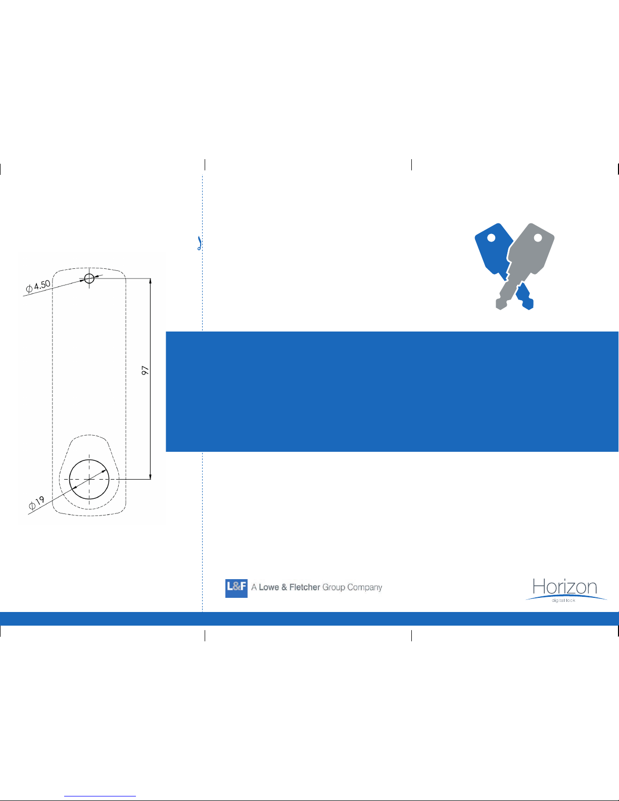
Please check that template is
correct size before use –
copies can be distorted
Euro-Locks
Si
cherheitseinrichtungen GmbH
Am Bruchwald 22
66280
Sulzbach/Neuweiler
T: +49 (0) 6897 9072 0
F: +49 (0) 6897 9072 99
E: vertrieb@euro-locks.de
W: www.euro-locks.de
Cut Here
INSTALLATION
INSTRUCTIONS
3950 - Horizon
Surface Mounted
Digital Combination Locks
INSTALLATION INSTRUCTIONS
3950 – Horizon Surface Mounted
Fitting Instructions
The Digital Combination Lock can be tted to cupboards,
cabinets and lockers etc. as an original tment, or as a direct
replacement for existing cam locks.
Special Notes
Before installing the Digital Combination Lock, load the battery
and familiarize yourself with the operation and programming.
Unless manufactured to special order, the lock is supplied in the
“PRIVATE” operating mode with a four-digit code.
In this mode, the user must enter a four-digit User Code to open
it. The unit will re-lock itself once open. The lock can be opened at
any time using the Master Code.
Unless manufactured to special order, the default
Master Code is 11 33 55 77 and the default User Code is 22 44.
These codes are common to all standard locks and it is
very important that you set your own personal Master and
User Codes.
Your lock is not secure until you have changed the default
Master Code and User Code.
Keep a safe record of your master code as it is not possible to
make any programming changes without it.
Please see programming guide to set your own codes.
Installation Guide
ENSURE BATTERY IS FITTED BEFORE FIXING TO CLOSURE
Step 1 Place template on door and mark ONE 4.5mm (3/16”) hole
and ONE 19mm (3/4”) hole in the handle position. (See
installation template for details)
Step 2 Drill both xing holes.
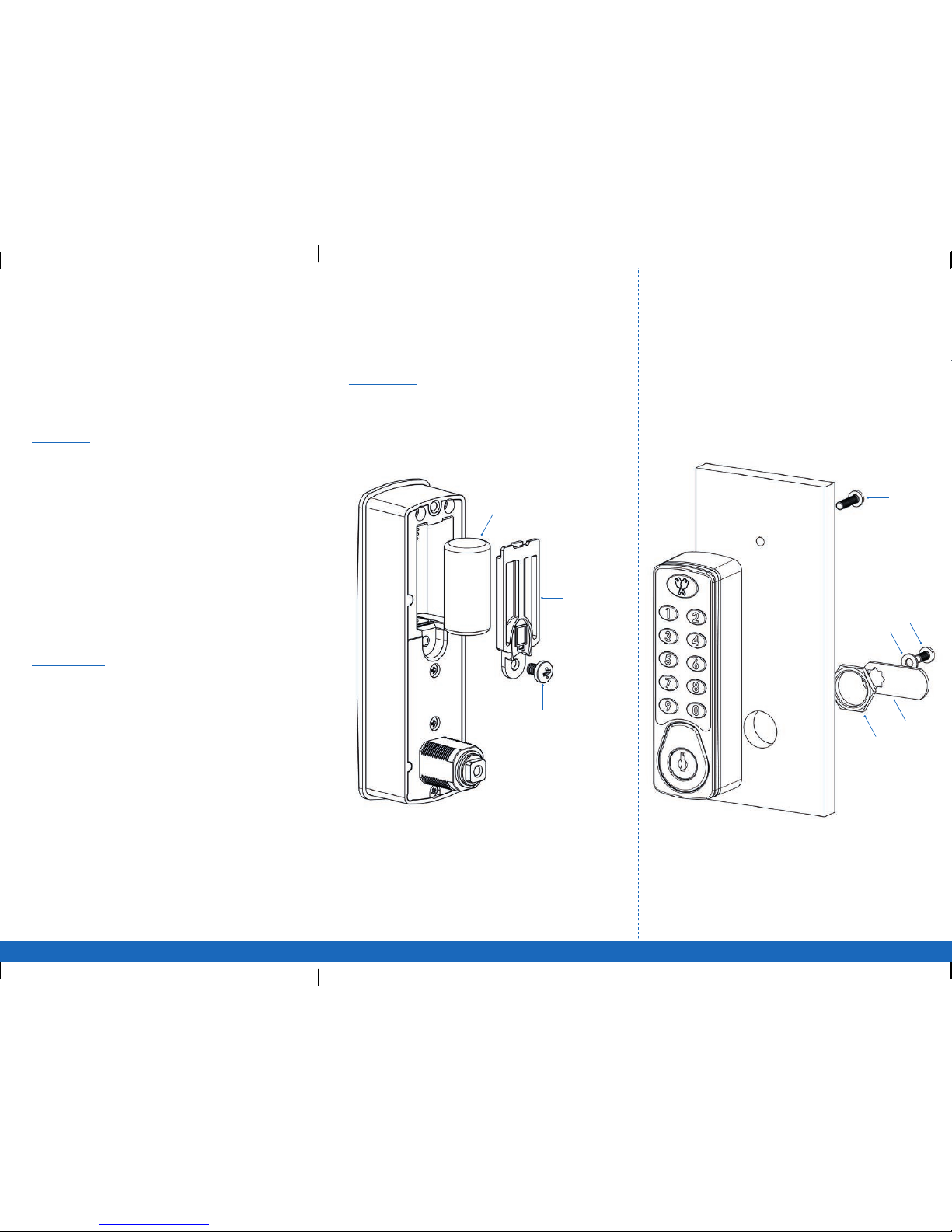
Step 3 Fit the trim ring to the lock ensuring that the slightly thinner
side of the ring goes onto the lock rst.
Step 4 Fit the Digital Combination Lock to the door by passing the
threaded spindle through the 19mm (3/4”) hole.
Step 5 Fit and tighten the xing nut and xing screw. The length of the
xing screw should be selected according to the door panel
thickness to give a nominal insertion depth of 8mm into the lock.
Step 6 Select the cam which suits your door and frame and attach it to
the square shaft at the end of the spindle using the M4 x 8 patch
screw.and at washer provided.
Step 7 Check the operation of the lock using the factory User Code 22 44.
Step 8 If the lock is functioning correctly, CHANGE THE DEFAULT
MASTER CODE 11 33 55 77 and DEFAULT USER CODE 22 44
and program the lock using the programming and operating
instructions enclosed.
CR123
Battery
Battery
cover
M4 Patch
Screw
Cam
Washer
Fixing
Nut
Cam
M4 screw
Fixing
screw
Inserting Battery
Step 1 Remove all packaging.
Step 2 Insert battery CR123. As shown.
Step 3 Secure battery with battery cover.
Step 4 M4 screw
 Loading...