

Page 1

Page 2

2/32
00121304, Version 1.1
Page 3
Inhaltsverzeichnis / Table of contents
EINFÜHRUNG ................................................................................................................................................... 4
Produktmerkmale ........................................................................................................................................... 4
SICHERHEITSHINWEISE ................................................................................................................................. 5
GERÄTEBESCHREIBUNG............................................................................................................................... 7
INSTALLATION ................................................................................................................................................ 8
Befestigung .................................................................................................................................................... 8
ANSCHLÜSSE .................................................................................................................................................. 9
DMX512-Ansteuerung .................................................................................................................................... 9
Anschluss ans Netz ........................................................................................................................................ 9
Stromversorgung von weiteren Geräten ........................................................................................................ 9
BEDIENUNG ................................................................................................................................................... 10
Menüstruktur ................................................................................................................................................ 10
Standalone-Betrieb ...................................................................................................................................... 10
DMX-Betrieb ................................................................................................................................................. 12
REINIGUNG UND WARTUNG ........................................................................................................................ 16
UMWELTSCHUTZ .......................................................................................................................................... 16
TECHNISCHE DATEN .................................................................................................................................... 17
Zubehör ........................................................................................................................................................ 17
INTRODUCTION ............................................................................................................................................. 18
Product features ........................................................................................................................................... 18
SAFETY INSTRUCTIONS............................................................................................................................... 19
DESCRIPTION OF THE DEVICE ................................................................................................................... 21
INSTALLATION .............................................................................................................................................. 22
Attachment ................................................................................................................................................... 22
CONNECTIONS .............................................................................................................................................. 23
DMX512 control ........................................................................................................................................... 23
Connection to the mains .............................................................................................................................. 23
Power supply of further devices ................................................................................................................... 23
OPERATION ................................................................................................................................................... 24
Menu structure ............................................................................................................................................. 24
Stand-alone mode ........................................................................................................................................ 24
DMX operation ............................................................................................................................................. 26
CLEANING AND MAINTENANCE ................................................................................................................. 30
PROTECTING THE ENVIRONMENT ............................................................................................................. 30
TECHNICAL SPECIFICATIONS ..................................................................................................................... 31
Accessories .................................................................................................................................................. 31
Diese Bedienungsanleitung gilt für die Artikelnummer / This user manual is valid for the article number:
Das neueste Update dieser Bedienungsanleitung finden Sie im Internet unter:
You can find the latest update of this user manual in the Internet under:
www.eurolite.de
42103493
3/32
00121304, Version 1.1
Page 4
BEDIENUNGSANLEITUNG
LED STP-14 Sunbar
GEFAHR! Elektrischer Schlag durch Kurzschluss
Seien Sie besonders vorsichtig beim Umgang mit gefährlicher Netzspannung. Bei dieser
Spannung können Sie einen lebensgefährlichen elektrischen Schlag erhalten. Öffnen Sie
das Gerät niemals und schützen Sie es vor Feuchtigkeit und Nässe.
Lesen Sie vor der Verwendung des Geräts diese Bedienungsanleitung. Sie erhalten dadurch
wichtige Hinweise für den korrekten Betrieb.
Alle Personen, die mit der Aufstellung, Inbetriebnahme, Bedienung, Wartung und Instandhaltung dieses
Gerätes zu tun haben, müssen
- entsprechend qualifiziert sein
- diese Bedienungsanleitung genau beachten
- die Bedienungsanleitung als Teil des Produkts betrachten
- die Bedienungsanleitung während der Lebensdauer des Produkts behalten
- die Bedienungsanleitung an jeden nachfolgenden Besitzer oder Benutzer des Produkts weitergeben
- sich die letzte Version der Anleitung im Internet herunter laden
EINFÜHRUNG
Wir freuen uns, dass Sie sich für eines unserer Produkte entschieden haben. Wenn Sie nachfolgende
Hinweise beachten, sind wir sicher, dass Sie lange Zeit Freude an Ihrem Kauf haben werden.
Produktmerkmale
3in1-LED-Sunbar mit warmweißen Beam-Effekten, Stroboskop und Ambientlight
• 3 beeindruckende Effekte in einem Gerät: Beam-Effekt, Stroboskop und Ambientlight
• 14 warmweiße 3-W-LEDs mit 6,5° Abstrahlwinkel für enge Beams
• 120 helle RGB-LEDs für Stimmungslicht und Farbanimationen
• 180 kaltweiße LEDs für schnelle, dynamische Strobe-Effekte
• Beim Einsatz von Nebel kommen die Effekte besonders gut zur Geltung
• Alle 3 LED-Arten sind aufgeteilt in unterschiedliche Segmente, die über DMX einzeln angesteuert
werden können
• Auto-, Musik-, Master/Slave- und DMX-Modus
• Integrierte Showprogramme im Auto- und Musikmodus
• Direkte Farbwahl für 10 Farben
• Stufenlose RGB-Farbmischung, Lauflicht, Dimmer und Strobe-Effekt mit variabler Geschwindigkeit und
über Zufallsgenerator
• Flickerfreie Projektion
• Adressierung und Einstellungen über Steuereinheit mit 4-stelliger LED-Anzeige
• Musiksteuerung über eingebautes Mikrofon mit einstellbarer Mikrofonempfindlichkeit
• 2, 6, 34 oder 37 DMX-Kanäle wählbar
• 2 schwenkbare Montagebügel
• P-Con-Netzanschluss mit Durchschleifausgang zur Spannungsversorgung von bis zu 8 Geräten
• Reine Konvektionskühlung über Kühlrippen, keine Lüfter, besonders leise im Betrieb
4/32
00121304, Version 1.1
Page 5
SICHERHEITSHINWEISE
WARNUNG!
Lesen Sie aufmerksam die Sicherheitshinweise und benutzen Sie das Produkt nur wie in dieser
Anleitung beschrieben, damit es nicht versehentlich zu Verletzungen oder Schäden kommt.
Verwendungszweck
• Bei diesem Gerät handelt es sich um einen LED-Leiste, mit dem sich dekorative Lichteffekte erzeugen
lassen. Das Gerät ist für professionelle Anwendungen im Bereich der Veranstaltungstechnik vorgesehen
(z. B. auf Bühnen). Es ist nicht für die Raumbeleuchtung in Haushalten geeignet.
• Verwenden Sie das Produkt ausschließlich gemäß den hier gegebenen Vorgaben. Bei Schäden, die durch
Nichtbeachten dieser Anleitung verursacht werden, erlischt der Garantieanspruch. Für Folgeschäden wird
keine Haftung übernommen.
• Bei Sach- oder Personenschäden, die durch unsachgemäße Handhabung oder Nichtbeachten der
Sicherheitshinweise verursacht werden, übernehmen wir keine Haftung und es erlischt jeder
Garantieanspruch.
• Aus Sicherheitsgründen ist das eigenmächtige Umbauen oder Verändern des Geräts nicht gestattet und
hat den Verfall der Garantieleistung zur Folge.
Gefahr durch Elektrizität
• Das Gerät ist nur zur Verwendung im Innenbereich geeignet. Benutzen Sie es nicht im Freien. Setzen Sie
es niemals Regen oder Feuchtigkeit aus. Bewahren Sie es nicht in feuchten Räumen auf.
• Um Stromschläge zu vermeiden, niemals irgendeinen Teil des Produkts öffnen. Im Geräteinneren befinden
sich keine vom Benutzer zu wartende Teile.
• Schließen Sie das Gerät nur an eine vorschriftsmäßig installierte Steckdose an, deren Spannung und
Frequenz mit dem Typenschild des Geräts genau übereinstimmt und die über einen
Fehlerstromschutzschalter (FI) abgesichert ist. Wenn der Netzstecker mit einem Schutzkontakt
ausgestattet ist, muss er an eine Steckdose mit Schutzleiter angeschlossen werden. Deaktivieren Sie
niemals den Schutzleiter eines Netzkabels. Nichtbeachtung kann zu Schäden am Gerät und zu
Verletzungen des Benutzers führen.
• Die Steckdose muss gut zugänglich sein, damit Sie im Bedarfsfall den Netzstecker schnell ziehen können.
• Fassen Sie den Netzstecker niemals mit nassen Händen an, da die Gefahr eines Stromschlags besteht.
• Das Netzkabel darf nicht geknickt oder gequetscht werden. Halten Sie es von heißen Oberflächen und
scharfen Kanten fern.
• Ziehen Sie den Netzstecker nie am Kabel aus der Steckdose, fassen Sie immer am Stecker an.
• Trennen Sie das Gerät vom Stromnetz bei längerem Nichtgebrauch, bevor Sie es reinigen und wenn
Gewitter auftreten.
• Setzen Sie das Gerät keinen hohen Temperaturen, direktem Sonnenlicht, Tropf- oder Spritzwasser,
starken Vibrationen sowie hohen mechanischen Beanspruchungen aus. Stellen Sie keine mit Flüssigkeit
gefüllten Gegenstände sowie offene Brandquellen wie brennende Kerzen auf oder direkt neben dem Gerät
ab.
• Sorgen Sie dafür, dass keine Gegenstände in das Gerät fallen können, insbesondere Metallteile.
• Lassen Sie Reparaturen am Gerät oder am Netzkabel nur von qualifiziertem Fachpersonal durchführen.
Reparaturen müssen durchgeführt werden, wenn sichtbare Schäden am Gerät oder am Netzkabel
vorhanden sind, Flüssigkeiten oder Objekte in das Gerät gelangt sind, das Gerät Regen ausgesetzt war,
das Gerät heruntergefallen ist oder wenn Funktionsstörungen auftreten.
• Die Reinigung beschränkt sich auf die Oberfläche. Dabei darf keine Feuchtigkeit in Anschlussräume oder
an Netzspannung führende Teile gelangen. Wischen Sie das Produkt nur mit einem fusselfreien,
angefeuchteten Tuch ab. Niemals Lösungsmittel oder scharfe Reinigungsmittel verwenden.
Gefahr für Kinder und Personen mit eingeschränkter Fähigkeit
• Das Gerät ist kein Spielzeug. Halten Sie es vor Kindern und Haustieren fern. Lassen Sie
Verpackungsmaterial nicht achtlos liegen. Betreiben Sie das Gerät nicht unbeaufsichtigt.
• Das Gerät darf nur von Personen benutzt werden, die über ausreichende physische, sensorische und
geistige Fähigkeiten sowie über entsprechendes Wissen und Erfahrung verfügen. Andere Personen dürfen
das Gerät nur benutzen, wenn sie von einer für ihre Sicherheit zuständigen Person beaufsichtigt oder
angeleitet werden.
5/32
00121304, Version 1.1
Page 6

Warnung vor Verbrennung und Brand
• Der zulässige Umgebungstemperaturbereich (Ta) beträgt -5 bis +45 °C. Verwenden Sie das Gerät niemals
außerhalb dieses Temperaturbereichs.
• Die Gehäusetemperatur (Tc) kann im Betrieb bis zu 65 °C betragen. Vermeiden Sie den Kontakt mit
Personen oder Gegenständen.
• Der Mindestabstand zur beleuchteten Fläche beträgt 10 cm. Der Wert ist am Gerät über das Bildzeichen
angegeben: .
---m
• Halten Sie das Gerät vor leicht entflammbaren Materialien fern. Platzieren Sie es so, dass im Betrieb eine
ausreichende Luftzirkulation gewährleistet ist. Das Gerät muss einen Mindestabstand von 50 cm zu
angrenzenden Flächen haben und die Lüftungsöffnungen am Gehäuse dürfen auf keinen Fall abgedeckt
werden.
Warnung vor Verletzungen
• Nicht direkt in die Lichtquelle blicken. Personen mit lichtempfindlicher Epilepsie könnten epileptische
Anfälle erleiden oder bewusstlos werden.
• Stellen Sie sicher, dass das Gerät fachgerecht und sicher aufgestellt oder befestigt ist und nicht
herunterfallen kann. Beachten Sie bei der Installation die gesetzlichen, nationalen Sicherheitsvorschriften
insbesondere die Bestimmungen der EN 60598-2-17.
• Versuchen Sie niemals, die Installation selbst vorzunehmen, wenn Sie nicht über eine ausreichende
Qualifikation verfügen, sondern beauftragen Sie einen professionellen Installateur. Unsachgemäße
Installationen können zu Verletzungen und/oder zur Beschädigung von Eigentum führen.
• Der Hersteller haftet nicht für Schäden, die durch unsachgemäße Installation und unzureichende Sicher-
heitsvorkehrungen verursacht werden.
• Bei einer Montage über Kopf ist das Gerät immer durch eine zweite Befestigung (z. B. Fangseil oder
Fangnetz) zu sichern.
• Während Montage- und Wartungsarbeiten muss der Bereich unterhalb des Geräts abgesperrt sein.
• Bei gewerblicher Nutzung sind die landesspezifischen Unfallverhütungsvorschriften des Verbandes der
gewerblichen Berufsgenossenschaften für elektrische Anlagen und Betriebsmittel unbedingt zu beachten.
Vorsicht - Sachschäden
• Schließen Sie das Gerät niemals über einen Dimmer an die Netzspannung an.
• Lichteffekte sind generell nicht für den Dauerbetrieb konzipiert. Längere Betriebszeiten sollten immer durch
Pausen unterbrochen werden, um die Lebensdauer des Geräts erhöhen.
• Vermeiden Sie es das Gerät in kurzen Intervallen ein- und auszuschalten. Dadurch reduziert sich die
Lebensdauer des Geräts erheblich.
• Nehmen Sie das Gerät niemals gleich in Betrieb, nachdem es starken Temperaturschwankungen
ausgesetzt wurde. Das dabei entstehende Kondenswasser kann unter Umständen das Gerät zerstören.
Lassen Sie das Gerät ausgeschaltet auf Zimmertemperatur kommen. Warten Sie bis das Kondenswasser
verdunstet ist.
• Benutzen Sie die Originalverpackung, um das Gerat bei Transport und Lagerung optimal vor
Erschütterungen, Staub und Feuchtigkeit zu schützen.
• Wenn am Gerät ein Etikett mit Seriennummer angebracht ist, darf dieses nicht entfernt werden, da
ansonsten der Garantieanspruch erlischt.
6/32
00121304, Version 1.1
Page 7
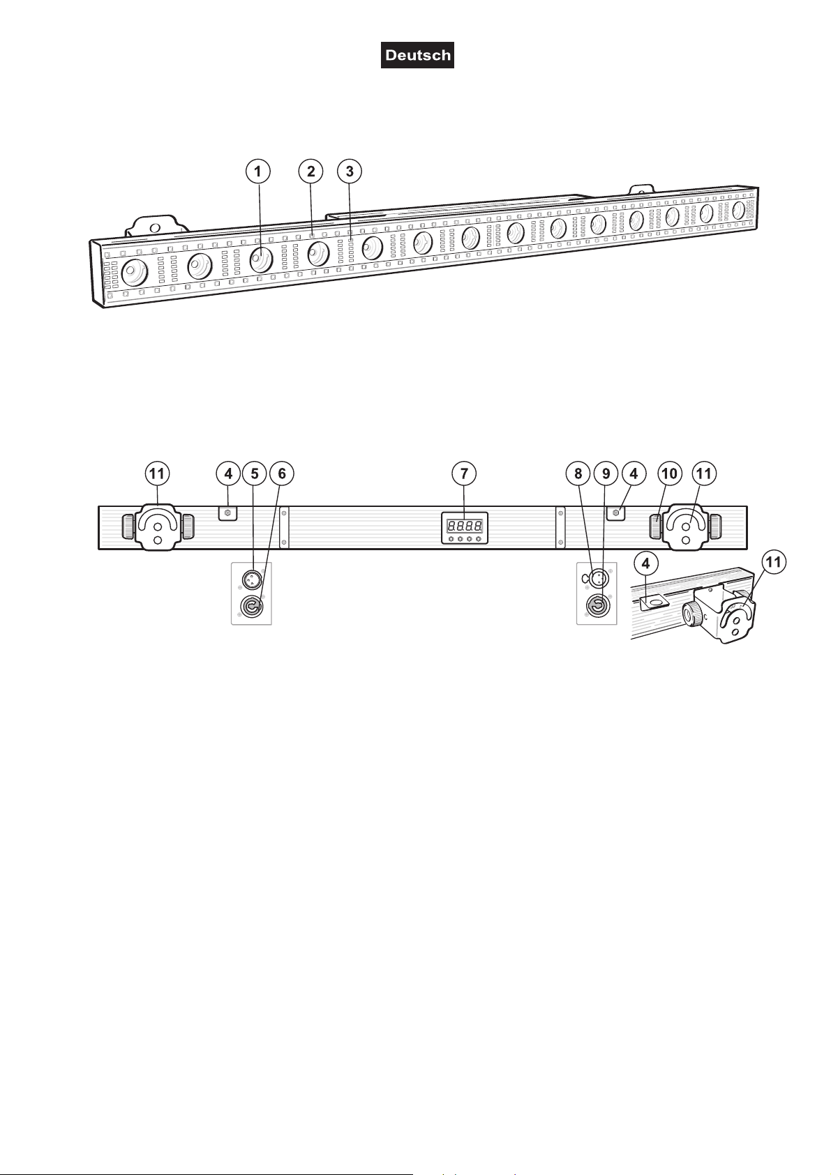
GERÄTEBESCHREIBUNG
(1) 14 warmweiße LEDs für Beam-Effekte
(2) 120 RGB-LEDs für Farbanimationen
(3) 180 kaltweiße LEDs für Strobe-Effekte
(4) Fangseilöse
(5) DMX-Eingang
(6) Netzanschluss
(7) Display mit vier Bedientasten
(8) DMX-Ausgang
(9) Netzdurchschleifausgang
(10) Feststellschraube
(11) Montagebügel
7/32
00121304, Version 1.1
Page 8
INSTALLATION
WARNUNG! Verletzungsgefahr durch Herabfallen
Über Kopf installierte Geräte können beim Herabstürzen erhebliche Verletzungen verursachen!
Stellen Sie sicher, dass das Gerät sicher installiert ist und nicht herunterfallen kann. Die Montage
darf nur durch eine Fachkraft erfolgen, die mit den Gefahren und den einschlägigen Vorschriften
hierfür vertraut ist.
Das Gerät kann an einer Traverse oder einer anderen geeigneten Struktur befestigt werden. Die Montage
darf niemals freischwingend erfolgen.
1 Die tragende Struktur muss mindestens für das Zehnfache aller montierten Geräte ausgelegt sein.
2 Sperren Sie den Arbeitsbereich während der Montage und arbeiten Sie von einer stabilen Plattform aus.
3 Verwenden Sie Montagematerial, das für die Struktur geeignet ist und die Last des Geräts tragen kann.
Geeignetes Montagematerial finden Sie im Abschnitt „Zubehör“.
4 Sichern Sie das Gerät mit einem Fangseil oder einer anderen geeigneten Einrichtung zusätzlich ab.
Diese zweite Aufhängung muss auf Grundlage der aktuellsten Arbeitsschutzbestimmungen ausreichend
dimensioniert und so angebracht sein, dass im Fehlerfall der Hauptaufhängung kein Teil der Installation
herabfallen kann. Für die Befestigung eines Fangseils ist eine entsprechende Öse am Gerät montiert.
Befestigen Sie das Sicherungsseil so, dass der Fallweg des Geräts nicht mehr als 20 cm betragen kann.
5 Zum Ausrichten des Geräts lösen Sie die Feststellschrauben an den zwei Montagebügeln, stellen die
gewünschte Neigung ein und ziehen die Schrauben wieder fest an.
6 Nach der Montage muss das Gerät regelmäßig gewartet und überprüft werden, um mögliche Korrosion,
Verformung und Lockerung zu vermeiden.
Befestigung
Vergewissern Sie sich vor der Montage, dass die Montagefläche mindestens die 10-fache Punktbelastung
des Eigengewichtes des Gerätes aushalten kann.
Der Installationsort muss so gewählt werden, dass das Gerät absolut plan an einem festen, erschütterungsfreien, schwingungsfreien und feuerfesten Ort befestigt werden kann. Mittels Wasserwaage muss überprüft
werden, dass das Gerät absolut plan befestigt wurde.
Das Gerät muss außerhalb des Handbereichs von Personen installiert werden.
Die Festigkeit der Installation hängt entscheidend von der Befestigungsunterlage (Bausubstanz, Werkstoff)
wie z. B. Holz, Beton, Gasbeton, Mauersteine ab. Deshalb muss das Befestigungsmaterial unbedingt auf
den jeweiligen Werkstoff abgestimmt werden. Erfragen Sie die passende Dübel/Schraubenkombination von
einem Fachmann unter Angabe der max. Belastbarkeit und des vorliegenden Werkstoffes.
Das Gerät muss immer über alle Befestigungslöcher angebracht werden. Verwenden Sie geeignete
Schrauben und vergewissern Sie sich, dass die Schrauben fest mit dem Untergrund verbunden sind.
Vorgehensweise:
Schritt 1: An den Montagebügeln des Gerätes befinden sich die Löcher zur Installation.
Schritt 2: Halten Sie das Gerät mit den Montagebügeln an die Stelle, wo es installiert werden soll.
Schritt 3: Markieren Sie Ihre Bohrlöcher mit einem Bleistift oder einem geeigneten Werkzeug.
Schritt 4: Bohren Sie die Löcher.
Schritt 5: Halten Sie das Gerät mit den Montagebügeln in der gewünschten Position und schrauben Sie
sie fest.
Stellen Sie den Neigungswinkel über die Montagebügel ein und ziehen Sie die Feststellschrauben gut fest.
8/32
00121304, Version 1.1
Page 9
ANSCHLÜSSE
DMX512-Ansteuerung
Für die Ansteuerung des Geräts per DMX512 ist eine Datenverbindung notwendig. Das Gerät verfügt dazu
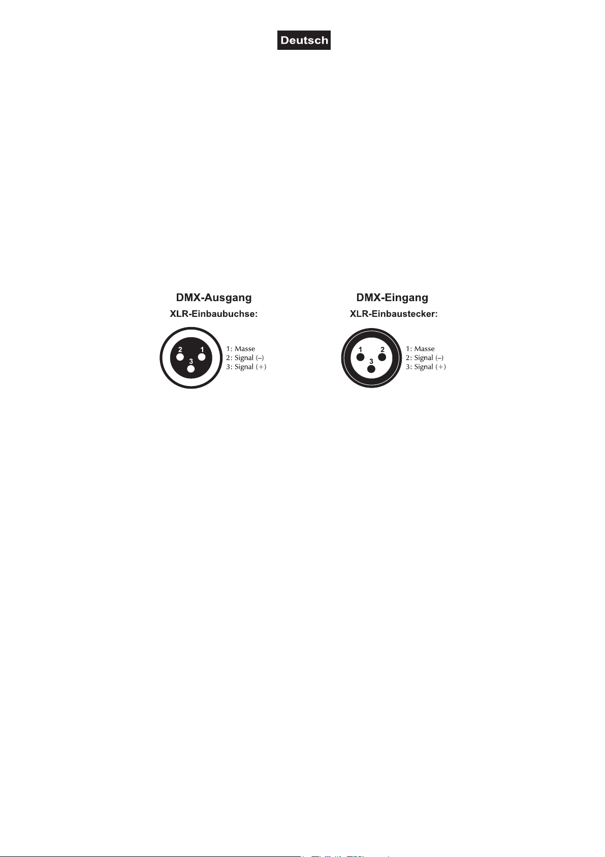
über 3-polige XLR-Anschlüsse.
1 Verbinden Sie den Ausgang Ihres Controllers mit dem DMX-Eingang DMX IN des Geräts über ein DMX-
Kabel.
2 Verbinden Sie den DMX-Ausgang DMX OUT des Geräts mit dem DMX-Eingang des nächsten Geräts in
der Kette. Verbinden Sie immer einen Ausgang mit dem Eingang des nächsten Geräts bis alle Geräte
angeschlossen sind.
3 Am letzten Gerät muss die DMX-Leitung durch einen Abschlusswiderstand abgeschlossen werden. Dazu
wird ein XLR-Stecker in den DMX-Ausgang am letzten Gerät gesteckt, bei dem zwischen Signal (–) und
Signal (+) ein 120-Ω-Widerstand eingelötet ist.
4 Ab einer Kabellänge von 300 m oder nach 32 angeschlossenen DMX-Geräten sollte das Signal mit Hilfe
eines DMX-Aufholverstärkers verstärkt werden, um eine fehlerfreie Datenübertragung zu gewährleisten.
Belegung der XLR-Verbindung:
Anschluss ans Netz
Das Gerät verfügt über ein Schaltnetzteil, das eine Netzspannung zwischen 100 und 240 Volt erlaubt.
1 Das Gerät ist mit einer verriegelbaren Netzanschlussbuchse ausgestattet. Schließen Sie das Netzkabel
an und drehen Sie es nach rechts bis es einrastet. Stecken Sie den Netzstecker in eine geerdete
Schutzkontaktsteckdose ein. Damit ist das Gerät eingeschaltet.
2 Zum Ausschalten ziehen Sie den Netzstecker aus der Steckdose.
3 Schließen Sie das Gerät nicht über einen Dimmer an die Netzspannung an. Für besseren Bedienkomfort
verwenden Sie eine schaltbare Steckdose.
Stromversorgung von weiteren Geräten
Über den Netzausgang POWER OUT können weitere Geräte mit Strom versorgt werden. Zum
Zusammenschalten der Geräte, verbinden Sie immer den Ausgang POWER OUT mit dem Eingang POWER
IN des nächsten Geräts bis alle Geräte angeschlossen sind. Passende Netzkabel mit P-Con-Stecker sind
optional erhältlich. Auf diese Weise lassen sich bis zu 8 Geräte bei 230/240 Volt Netzspannung und bis zu 4
Geräte bei 110/115 Volt Netzspannung zusammenschalten.
9/32
00121304, Version 1.1
Page 10
BEDIENUNG
Nach dem Anschluss ans Netz ist das Gerät betriebsbereit. Das Display zeigt die zuletzt eingestellte
Betriebsart. Nehmen Sie nun die notwendigen Menüeinstellungen für die jeweilige Betriebsart mit den
Bedientasten vor. Auch wenn Sie das Gerät vom Stromnetz trennen, bleiben alle Einstellungen gespeichert.
Das Gerät kann entweder im Standalone-Modus über das Bedienfeld oder im DMX-gesteuerten Modus über
einen handelsüblichen DMX-Controller betrieben werden.
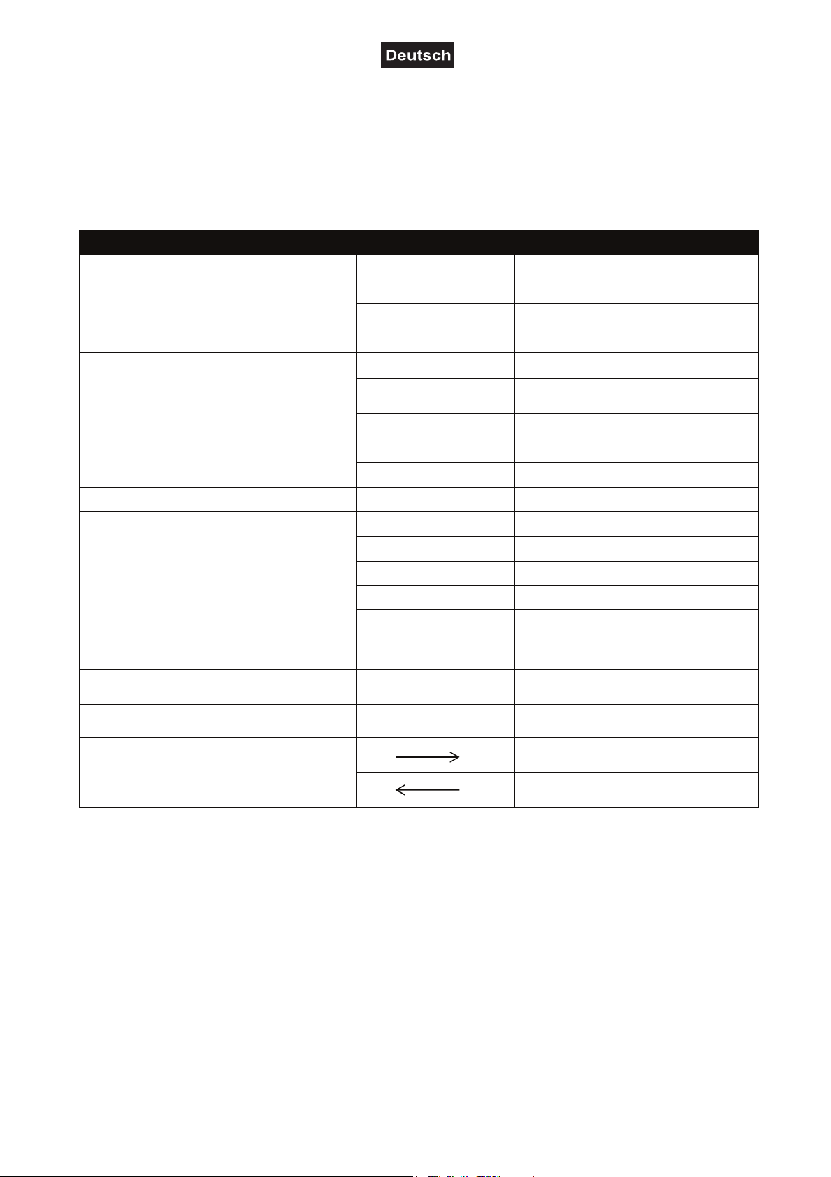
Menüstruktur
DMX-Betrieb
Automatikbetrieb
Musiksteuerung
Slave-Modus
Farbmischung
Farbvoreinstellungen
Modus
Anzeige
37CH d001-476 37-Kanal-Modus und Startadresse
Addr
Shou
Soud
SLAV Slave Slave-Modus
Colo
StAt CL01-11
34CH d001-479 34-Kanal-Modus und Startadresse
6CH d001-507 6-Kanal-Modus und Startadresse
2CH
Sh 1-7 Showprogramm 1-7
Sp 1-9
St 0-9
So1-4
Sen 1-9 Mikrofonempfindlichkeit niedrig > hoch
r000-255 Rot
g000-255 Grün
b000-255 Blau
U000-255 Warmweiße LEDs
S000-255 Kaltweiße LEDs
St 0-9
d001-511 2-Kanal-Modus und Startadresse
Ablaufgeschwindigkeit 1-9 langsam >
schnell
Strobe-Effekt 0-9 langsam > schnell
Showprogramm 1-4
Kaltweiße LEDs: Strobe-Effekt
langsam > schnell
Konstantes Leuchten in einer von 10
Farben CL02-11; LEDs aus: CL01
Funktion
Information
Richtungsvorgabe für den
Automatikbetrieb und die
Musiksteuerung
Info Ver VVxx
dir
Anzeige Software-Version
Laufrichtung der internen Programme
„Shou“ und „Soud“ von links nach rechts
Laufrichtung der internen Programme
„Shou“ und „Soud“ von rechts nach links
Standalone-Betrieb
Automatikbetrieb
Im Automatikbetrieb stehen verschiedene Showprogramme zur Verfügung die mit einer einstellbaren
Geschwindigkeit ablaufen.
1 Drücken Sie die Taste MENU so oft, bis das Display die Betriebsart Shou anzeigt. Bestätigen Sie mit der
Taste ENTER. Wählen Sie das gewünschte Showprogramm Sh 1-7 mit den Tasten UP und DOWN.
Bestätigen Sie mit der Taste ENTER.
2 Stellen Sie die mit den Tasten UP und DOWN die gewünschte Ablaufgeschwindigkeit des Programms
von Sp 1 (langsam) bis Sp 9 (schnell) ein. Bestätigen Sie mit der Taste ENTER.
3 Als letzter Menüpunkt kann der Strobe-Effekt eingestellt werden. Wählen Sie mit den Tasten UP und
DOWN die gewünschte Blitzfrequenz: St 1 (langsam) bis St 9 (schnell). Mit der Einstellung St 0 ist der
Strobe-Effekt deaktiviert. Bestätigen Sie mit der Taste ENTER.
10/32
00121304, Version 1.1
Page 11

Musiksteuerung
Durch das integrierte Mikrofon lassen sich die integrierten Showprogramme im Rhythmus der Musik (bei
deutlichem Bassschlag) optimal mit dem Gerät wiedergeben.
1 Drücken Sie die Taste MENU so oft, bis das Display die Betriebsart Soud anzeigt. Bestätigen Sie mit der
Taste ENTER. Wählen Sie das gewünschte Showprogramm So 1-4 mit den Tasten UP und DOWN.
Bestätigen Sie mit der Taste ENTER.
2 Passen Sie mit den Tasten UP und DOWN die Mikrofonempfindlichkeit an die Lautstärke der Musik an
(sen 1 = niedrig, sen 9 = hoch). Bestätigen Sie mit der Taste ENTER.
Master/Slave-Betrieb mit mehreren Geräten
Es lassen sich mehrere Geräte zusammenschalten (max. 32). Das Hauptgerät (Master) kann dann alle
Nebengeräte (Slave) synchron steuern ohne die Notwendigkeit eines DMX-Controllers. Die Geräte müssen
auf die jeweilige Betriebsart eingestellt werden.
1 Konfigurieren Sie zuerst alle Slave-Geräte vor dem Anschluss an das Master-Gerät. Drücken Sie dazu
die Taste MENU so oft, bis das Display SLAV anzeigt. Bestätigen Sie mit der Taste ENTER.
2 Verbinden Sie den DMX-Ausgang des Master-Geräts mit dem DMX-Eingang des ersten Slave-Geräts.
Verbinden Sie dann den DMX-Ausgang des ersten Slave-Geräts mit dem DMX-Eingang des zweiten
Slave-Geräts usw., bis alle Geräte in einer Kette angeschlossen sind. Das Master-Gerät muss das erste
Gerät in der Kette sein. Der DMX-Eingang darf nicht an einen DMX-Controller angeschlossen sein.
3 Wählen Sie am Master-Gerät die gewünschte Betriebsart. Die zusammengeschalteten Geräte arbeiten
nun synchron.
Individuelle Farbeinstellung
Der Farbmodus Colo bietet die Möglichkeit, jede der einzelnen Farben in der Helligkeit individuell
einzustellen. Das Gerät strahlt konstant mit dieser Farbeinstellung.
1 Drücken Sie die Taste MENU so oft, bis das Display die Betriebsart Colo anzeigt. Bestätigen Sie mit der
Taste ENTER.
2 Das Display zeigt nun den Buchstaben r für die Farbe an und den dazugehörigen Helligkeitswert. Stellen
Sie mit den Tasten UP und DOWN die gewünschte Helligkeit ein. Bestätigen Sie mit der Taste ENTER.
Jetzt kann die Farbe Grün eingestellt werden, danach Blau, Warmweiß und Kaltweiß.
3 Als letzter Menüpunkt kann der Strobe-Effekt für die kaltweißen LEDs eingestellt werden. Wählen Sie mit
den Tasten UP und DOWN die gewünschte Blitzfrequenz: St 1 (langsam) bis St 9 (schnell). Mit der
Einstellung St 0 ist der Strobe-Effekt deaktiviert. Bestätigen Sie mit der Taste ENTER.
Farbvoreinstellungen
Im Modus StAt strahlt das Gerät konstant in einer von 10 vorgegebenen Farben.
1 Drücken Sie die Taste MENU so oft, bis das Display die Betriebsart StAt anzeigt. Bestätigen Sie mit der
Taste ENTER.
2 Wählen Sie mit den Tasten UP und DOWN die gewünschte Farbe CL 02-11. Mit der Einstellung CL 01
werden die LEDs ausgeschaltet. Bestätigen Sie mit der Taste ENTER.
Information
Das Display kann die Software-Version anzeigen.
1 Drücken Sie die Taste MENU so oft, bis das Display die Betriebsart Info anzeigt. Bestätigen Sie mit der
Taste ENTER. Das Display zeigt Ver.
2 Bestätigen Sie erneut mit der Taste ENTER. Das Display zeigt nun die aktuelle Software-Version.
Richtungsvorgabe
Im Modus dir können Sie die Laufrichtung der internen Programme „Shou“ und „Soud“ festlegen.
1 Drücken Sie die Taste MENU so oft, bis das Display die Betriebsart dir anzeigt. Bestätigen Sie mit der
Taste ENTER.
2 Wählen Sie die gewünschte Laufrichtung mit den Tasten UP und DOWN. Bestätigen Sie mit der Taste
ENTER.
11/32
00121304, Version 1.1
Page 12

DMX-Betrieb
Anzahl der DMX-Kanäle und DMX-Startadresse einstellen
Für den Betrieb über einen Controller mit DMX512-Protokoll verfügt das Gerät über 37 Steuerkanäle. Es
kann aber auch in einen Modus mit 2, 6, oder 34 Kanälen umgeschaltet werden, wenn andere Funktionen
benötigt werden. Damit das Gerät vom Controller angesteuert werden kann, muss außerdem die DMXStartadresse eingestellt werden. Die Startadresse ist abhängig von Ihrem DMX-Controller. Lesen Sie hierzu
die Dokumentation des Geräts.
1 Drücken Sie die Taste MENU so oft, bis das Display die Betriebsart Addr anzeigt. Bestätigen Sie mit der
Taste ENTER.
2 Das Display zeigt 2 CH (2 DMX-Kanäle), 6 CH (6 DMX-Kanäle), 34 CH (34 DMX-Kanäle) oder 37 CH
(37 DMX-Kanäle) an. Wählen Sie mit den Tasten UP und DOWN die gewünschte Anzahl der DMX-
Kanäle. Bestätigen Sie mit der Taste ENTER.
3 Das Menü für die DMX-Startadresse wird aufgerufen A***. Stellen die Adresse mit den Tasten UP und
DOWN ein. Bestätigen Sie mit der Taste ENTER.
4 DMX wird angezeigt, indem das letzte Segment blinkt. Fehlen die Steuersignale, blinkt kein Segment im
Display.
Hinweis: Bitte vergewissern Sie sich, dass sich die Steuerkanäle nicht mit anderen Geräten überlappen,
damit das Gerät korrekt und unabhängig von anderen Geräten in der DMX-Verbindung funktioniert. Werden
mehrere Geräte auf eine Adresse definiert, arbeiten sie synchron.
Die LEDs des Geräts sind in verschiedene Segment-Gruppen mit jeweils 5 Segmenten aufgeteilt, die mit
dem nachfolgenden DMX-Protokoll individuell gesteuert werden können.
12/32
00121304, Version 1.1
Page 13

Funktionen im DMX-Betrieb
Kanal
Wert
Funktion
Kanal
Wert
Funktion
2-Kanal-Modus
000 – 009 Keine Funktion
010 – 044 Automatisches Programm 1: zufälliger Strobe-Effekt
045 – 079 Automatisches Programm 2: WW-LED + RGB-LED
080 – 114 Automatisches Programm 3: WW-LED + CW-LED
1
115 – 149 Automatisches Programm 4: RGB-LED + CW-LED
150 – 184 Automatisches Programm 5: WW-LED
185 – 219 Automatisches Programm 6: RGB-LED
220 – 254 Automatisches Programm 7: WW-LED
255 Musikgesteuertes Programm
2
000 - 255 Automatikbetrieb mit zunehmender Geschwindigkeit
6-Kanal-Modus
000 - 009 Keine Funktion
010 - 019 Alle WW-LEDs an, Kanal 4 Dimmer (0-100%)
020 - 029 Programm 1
030 – 039 Programm 2
040 – 049 Programm 3
050 – 059 Programm 4
060 - 069 Programm 5
070 – 079 Programm 6
080 – 089 Programm 7
090 – 099 Programm 8
100 - 109 Programm 9
1
WW-LED
110 – 119 Programm 10
120 - 129 Programm 11
130 - 139 Programm 12
140 – 149 Programm 13
150 – 159 Programm 14
160 – 169 Programm 15
170 – 179 Programm 16
180 – 189 Programm 17
190 – 199 Programm 18
200 – 209 Programm 19
210 - 219 Programm 20
220 – 229 Programm 21
230 – 239 Programm 22
240 – 255 Programm 23
000 – 009 Keine Funktion
010 – 031
2
RGB-LED
032 – 053 Programm 1
054 – 075 Programm 2
076 – 097 Programm 3
098 – 119 Programm 4
120 – 141 Programm 5
WW-LED-Programm
Alle RGB-LEDs an, Kanal 4
Dimmer (0-100%)
RGB-Programm
13/32
00121304, Version 1.1
Page 14

3
Kanal
Wert
Funktion
CW-LED
4
5
6
34-Kanal-Modus
142 – 163 Programm 6
164 – 185 Programm 7
186 – 207 Programm 8
208 – 229 Programm 9
230 – 251 Programm 10
252 – 255 Programm 11
000 – 009 Keine Funktion
010 – 027
Alle CW-LEDs an, Kanal 4 Dimmer
(0-100%)
028 – 045 Programm 1
046 – 063 Programm 2
064 – 081 Programm 3
082 – 099 Programm 4
100 – 117 Programm 5
118 – 135 Programm 6
CW-LED-Programm
136 – 153 Programm 7
154 – 171 Programm 8
172 – 189 Programm 9
190 – 207 Programm 10
208 – 225 Programm 11
226 – 243 Programm 12
244 – 255 Programm 13
000 – 255 Master Dimmer für alle LEDs 0-100%
000 – 255 Zunehmende Geschwindigkeit
000 – 009 Keine Funktion
010 – 255 Strobe-Effekt mit zunehmender Geschwindigkeit
1
2
3
4
5
6
7
8
9
10
11
12
13
14
15
16
17
18
19
000 – 255 WW-LEDs 1 (0-100%)
000 – 255 WW-LEDs 2 (0-100%)
000 – 255 WW-LEDs 3 (0-100%)
000 – 255 WW-LEDs 4 (0-100%)
000 – 255 WW-LEDs 5 (0-100%)
000 – 255 WW-LEDs 6 (0-100%)
000 – 255 WW-LEDs 7 (0-100%)
000 – 255 WW-LEDs 8 (0-100%)
000 – 255 WW-LEDs 9 (0-100%)
000 – 255 WW-LEDs 10 (0-100%)
000 – 255 WW-LEDs 11 (0-100%)
000 – 255 WW-LEDs 12 (0-100%)
000 – 255 WW-LEDs 13 (0-100%)
000 – 255 WW-LEDs 14 (0-100%)
000 – 255 RGB-LEDs Rot 1 (0-100%)
000 – 255 RGB-LEDs Grün 1 (0-100%)
000 – 255 RGB-LEDs Blau 1 (0-100%)
000 – 255 RGB-LEDs Rot 2 (0-100%)
000 – 255 RGB-LEDs Grün 2 (0-100%)
14/32
00121304, Version 1.1
Page 15

20
Kanal
Wert
Funktion
21
22
23
24
25
26
27
28
29
30
31
32
33
34
37-Kanal-Modus
000 – 255 RGB-LEDs Blau 2 (0-100%)
000 – 255 RGB-LEDs Rot 3 (0-100%)
000 – 255 RGB-LEDs Grün 3 (0-100%)
000 – 255 RGB-LEDs Blau 3 (0-100%)
000 – 255 RGB-LEDs Rot 4 (0-100%)
000 – 255 RGB-LEDs Grün 4 (0-100%)
000 – 255 RGB-LEDs Blau 4 (0-100%)
000 – 255 RGB-LEDs Rot 5 (0-100%)
000 – 255 RGB-LEDs Grün 5 (0-100%)
000 – 255 RGB-LEDs Blau 5 (0-100%)
000 – 255 SMD-CW-LEDs 1 (0-100%)
000 – 255 SMD-CW-LEDs 2 (0-100%)
000 – 255 SMD-CW-LEDs 3 (0-100%)
000 – 255 SMD-CW-LEDs 4 (0-100%)
000 – 255 SMD-CW-LEDs 5 (0-100%)
1
2
3
4
5
6
7
8
9
10
11
12
13
14
15
16
17
18
19
20
21
22
23
24
25
26
27
28
29
30
000 – 255 WW-LEDs 1 (0-100%)
000 – 255 WW-LEDs 2 (0-100%)
000 – 255 WW-LEDs 3 (0-100%)
000 – 255 WW-LEDs 4 (0-100%)
000 – 255 WW-LEDs 5 (0-100%)
000 – 255 WW-LEDs 6 (0-100%)
000 – 255 WW-LEDs 7 (0-100%)
000 – 255 WW-LEDs 8 (0-100%)
000 – 255 WW-LEDs 9 (0-100%)
000 – 255 WW-LEDs 10 (0-100%)
000 – 255 WW-LEDs 11 (0-100%)
000 – 255 WW-LEDs 12 (0-100%)
000 – 255 WW-LEDs 13 (0-100%)
000 – 255 WW-LEDs 14 (0-100%)
000 – 255 RGB-LEDs Rot 1 (0-100%)
000 – 255 RGB-LEDs Grün 1 (0-100%)
000 – 255 RGB-LEDs Blau 1 (0-100%)
000 – 255 RGB-LEDs Rot 2 (0-100%)
000 – 255 RGB-LEDs Grün 2 (0-100%)
000 – 255 RGB-LEDs Blau 2 (0-100%)
000 – 255 RGB-LEDs Rot 3 (0-100%)
000 – 255 RGB-LEDs Grün 3 (0-100%)
000 – 255 RGB-LEDs Blau 3 (0-100%)
000 – 255 RGB-LEDs Rot 4 (0-100%)
000 – 255 RGB-LEDs Grün 4 (0-100%)
000 – 255 RGB-LEDs Blau 4 (0-100%)
000 – 255 RGB-LEDs Rot 5 (0-100%)
000 – 255 RGB-LEDs Grün 5 (0-100%)
000 – 255 RGB-LEDs Blau 5 (0-100%)
000 – 255 CW-LEDs 1 (0-100%)
15/32
00121304, Version 1.1
Page 16

31
32
33
34
000 – 255 SMD-CW-LEDs 2 (0-100%)
000 – 255 SMD-CW-LEDs 3 (0-100%)
000 – 255 SMD-CW-LEDs 4 (0-100%)
000 – 255 SMD-CW-LEDs 5 (0-100%)
000 – 009 Keine Funktion
010 – 044 Automatisches Programm 1 zufälliger Strobe-Effekt
045 – 079 Automatisches Programm 2 (WW-LEDs + RGB-LEDs)
080 114 Automatisches Programm 3 (WW-LEDs + CW-LEDs)
35
115 – 149 Automatisches Programm 4 (RGB-LEDs + CW-LEDs)
150 – 184 Automatisches Programm 5 (WW-LEDs)
185 – 219 Automatisches Programm 6 (RGB-LEDs)
220 – 254 Au Automatisches to Programm 7 (CW-LEDs)
255 Musikgesteuertes Programm
36
37
000 – 255
000 – 009 Keine Funktion
010 – 255 Strobe-Effekt mit zunehmender Geschwindigkeit 0-100%
Automatisches Programm mit zunehmender
Geschwindigkeit 0-100%
REINIGUNG UND WARTUNG
Das Gerät sollte äußerlich in regelmäßigen Abständen von Verunreinigungen wie Staub usw. gereinigt
werden. Insbesondere die Linsen sollten sauber sein, damit das Licht mit maximaler Helligkeit abgestrahlt
werden kann.
1 Trennen Sie das Gerät vom Netz und lassen Sie es abkühlen, bevor Sie mit der Reinigung beginnen.
2 Reinigen Sie die Oberflächen mit einem fusselfreien, angefeuchteten Tuch. Verwenden Sie auf keinen
Fall Alkohol oder irgendwelche Lösungsmittel, da sonst die Gehäuseoberflächen beschädigt werden
könnten. Vermeiden Sie unbedingt das Eindringen von Nässe oder Feuchtigkeit in das Gerät.
3 Das Gerät muss trocken sein, bevor Sie es wieder einschalten.
Im Geräteinneren befinden sich keine zu wartenden Teile. Öffnen Sie das Gehäuse nicht. Unternehmen Sie
keine Reparaturversuche, da dies ein Sicherheitsrisiko darstellt. Wartungs- und Servicearbeiten sind
ausschließlich dem autorisierten Fachhandel vorbehalten. Sollten einmal Ersatzteile benötigt werden,
verwenden Sie bitte nur Originalersatzteile. Sollten Sie noch weitere Fragen haben, wenden Sie sich bitte an
Ihren Fachhändler.
UMWELTSCHUTZ
Informationen zur Entsorgung
Bitte übergeben Sie das Gerät bzw. die Geräte am Ende der Nutzungsdauer zur
umweltgerechten Entsorgung einem örtlichen Recyclingbetrieb. Geräte, die mit diesem Symbol
gekennzeichnet sind, dürfen nicht im Hausmüll entsorgt werden. Für weitere Informationen
wenden Sie sich bitte an Ihren Händler oder die zuständige örtliche Behörde. Entnehmen Sie
evtl. eingelegte Batterien und entsorgen Sie diese getrennt vom Produkt.
Als Endverbraucher sind Sie durch die Batterieverordnung gesetzlich zur Rückgabe aller
gebrauchten Batterien und Akkus verpflichtet. Die Entsorgung über den Hausmüll ist verboten.
Verbrauchte Batterien können Sie unentgeltlich bei den Sammelstellen Ihrer Gemeinde und
überall, wo Batterien verkauft werden, abgeben. Mit der Verwertung von Altgeräten und der
ordnungsgemäßen Entsorgung von Batterien und Akkus leisten Sie einen wichtigen Beitrag zum
Schutz unserer Umwelt.
16/32
00121304, Version 1.1
Page 17

TECHNISCHE DATEN
Spannungsversorgung: 100-240 V AC, 50/60 Hz
Gesamtanschlusswert: 95 W
Schutzklasse: I
DMX-Steuerkanäle: 2/6/34/37
DMX-Anschluss: 3-pol XLR
Musiksteuerung: über eingebautes Mikrofon
14 x 3 W WW (CREE)
LED-Typ:
Abstrahlwinkel: 6,5° (Beam-Effekt)
Maximale Umgebungstemperatur Ta: 45° C
Maximale Leuchtentemperatur im Beharrungszustand Tc: 65° C
Mindestabstand zu entflammbaren Oberflächen: 0,5 m
Mindestabstand zum angestrahlten Objekt: 0,1 m
Maße (L x B x H): 1000 x 90 x 85 mm
Gewicht: 3,9 kg
Zubehör
EUROLITE TPC-10 Klammer, silber Best.-Nr. 59006856
EUROLITE Sicherungsseil A 3x600mm bis 5kg, silber Best.-Nr. 58010310
EUROLITE DMX Kabel XLR 3pol 3m schwarz Best.-Nr. 3022785H
PSSO DMX Kabel XLR 3pol 3m schwarz Neutrik Best.-Nr. 30227810
PSSO PowerCon Verbindungskabel 3x1,5 3m Best.-Nr. 3023503R
PSSO PowerCon Netzkabel 3x1,5 1,5m H07RN-F Best.-Nr. 30235030
Technische Änderungen ohne vorherige Ankündigung und Irrtum vorbehalten. © 04.06.2019
120 x RGB (SMD 5050)
180 x CW (SMD 5730)
17/32
00121304, Version 1.1
Page 18

USER MANUAL
LED STP-14 Sunbar
DANGER! Electric shock caused by short-circuit
Be careful with your operations. With a dangerous voltage you can suffer a dangerous electric
shock when touching the wires. Never open the housing. Keep the device away from rain and
moisture.
Please read these instructions carefully before using the product. They contain important
information for the correct use of the product.
Every person involved with the installation, operation and maintenance of this device has to
- be qualified
- follow the instructions of this manual
- consider this manual to be part of the total product
- keep this manual for the entire service life of the product
- pass this manual on to every further owner or user of the product
- download the latest version of the user manual from the Internet
INTRODUCTION
Thank you for having chosen one of our products. If you follow the instructions given in this manual, we are
sure that you will enjoy this device for a long period of time.
Product features
3in1 LED sunbar with warm white beam effects, stroboscope and ambient light
• 3 striking effects in one device: beam effect, stroboscope and ambient light
• 14 warm white 3 W LEDs with 6.5° beam angle for clearly defined beams
• 120 bright RGB LEDs for mood lighting and color animations
• 180 cold white LEDs for fast, dynamic strobe effects
• When fog is used, the effects become especially attractive
• All 3 LED types are distributed in different segments which can be controlled individually via DMX
• Auto, music, master/slave and DMX mode
• Built-in auto and music show programs
• Direct color selection for 10 preset colors
• Stepless RGB color blend, chasers, dimmer and strobe effect with variable speed, random strobe effect
• Flicker-free projection
• Addressing and setting via control panel with 4-digit LED display
• Sound-control via built-in microphone with adjustable microphone sensitivity
• 2, 6, 34 or 37 DMX channels selectable
• Swivel mounting brackets
• P-Con power input and feed-through output to power up to 8 devices
• Pure convection cooling via cooling ribs, no fans, particularly quiet during operation
18/32
00121304, Version 1.1
Page 19

SAFETY INSTRUCTIONS
WARNING!
Please read the safety warnings carefully and only use the product as describe in this manual to
avoid accidental injury or damage.
Intended use
• This device is an LED bar for creating decorative lighting effects. This device is designed for professional
use in the field of event technology, e.g. on stage. It is not suitable for household lighting.
• Only use the device according to the instructions given herein. Damages due to failure to follow these
operating instructions will void the warranty! We do not assume any liability for any resulting damage.
• We do not assume any liability for material and personal damage caused by improper use or non-
compliance with the safety instructions. In such cases, the warranty/guarantee will be null and void.
• Unauthorized rebuilds or modifications of the device are not permitted for reasons of safety and render the
warranty invalid.
Danger due to electricity
• The device is suitable for indoor use only. Do not use it outdoors. Never expose it to rain or moisture. Do
not store it in rooms exposed to moisture.
• To reduce the risk of electric shock, do not open any part of the device. There are no serviceable parts
inside the device.
• Only connect the device to a properly installed mains outlet. The outlet must be protected by residual
current breaker (RCD). The voltage and frequency must exactly be the same as stated on the device. If the
mains cable is equipped with an earthing contact, then it must be connected to an outlet with a protective
ground. Never defeat the protective ground of a mains cable. Failure to do so could result in damage to the
device and possibly injure the user.
• The mains outlet must be easily accessible so that you can unplug the device quickly if need be.
• Never touch the mains plug with wet or damp hands. There is the risk of potentially fatal electric shock.
• The mains cable must not be bent or squeezed. Keep it away from hot surfaces or sharp edges.
• Never pull the mains cable to disconnect the mains plug from the mains outlet, always seize the plug.
• Unplug the device during lightning storms, when unused for long periods of time or before cleaning.
• Do not expose the device to any high temperatures, direct sunlight, dripping or splashing water, strong
vibrations or heavy mechanical stress.
•
Do not place any objects filled with liquids on the device.
• Do not place any open sources of fire, such as burning candles, on or directly next to the device.
• Make sure that objects cannot fall into the device, in particular metal parts.
• Only have repairs to the device or its mains cable carried out by qualified service personnel. Repairs are
required when the device or the mains cable is visibly damaged, liquid has been spilled or objects have
fallen into the device; when the device has been exposed to rain or moisture, has been dropped or
malfunctions occur.
• Cleaning of the device is limited to the surface. Make sure that moisture does not come into contact with
any areas of the terminal connections or mains voltage control parts. Only wipe off the product with a soft
lint-free and moistened cloth. Never use solvents or aggressive detergents.
Danger to children and people with restricted abilities
• This product is not a toy. Keep it out of the reach of children and pets. Do not leave packaging material
lying around carelessly. Never leave this device running unattended.
• This device may be used only by persons with sufficient physical, sensorial, and intellectual abilities and
having corresponding knowledge and experience. Other persons may use this device only if they are
supervised or instructed by a person who is responsible for their safety.
19/32
00121304, Version 1.1
Page 20

Warning – risk of burns and fire
• The admissible ambient temperature range (Ta) is -5 to +45°C. Do not operate the device outside of this
temperature range.
• The housing temperature (Tc) can be up to 65°C during use. Avoid contact by persons and materials.
• Do not illuminate surfaces within 10 cm of the device. This value is indicated on the device by the
---m
symbol.
• Do not use the device near highly flammable materials. Always place the device at a location where
sufficient air circulation is ensured. Leave 50 cm of free space around the device. Never cover the air vents
of the housing.
Warning – risk of injuries
• Do not look directly at the light source. Persons with light-sensitive epilepsy may suffer from epileptic
seizures or fall unconscious.
• Make sure that the product is set up or installed safely and expertly and prevented from falling down.
Comply with the standards and rules that apply in your country, in particular EN 60598-2-17.
• If you lack the qualification, do not attempt the installation yourself, but instead use a professional installer.
Improper installation can result in bodily injury and or damage to property.
• The manufacturer cannot be made liable for damages caused by incorrect installations or insufficient safety
precautions.
• For overhead use, always secure the device with a secondary safety attachment such as a safety bond or
safety net.
• Make sure that the area below the installation place is blocked when rigging, derigging or servicing the
device.
• For commercial use the country-specific accident prevention regulations of the government safety
organization for electrical facilities must be complied with at all times.
Caution – material damage
• This device must not be connected to the mains voltage by means of a dimmer.
• Lighting effects are not designed for permanent operation. Consistent operation breaks will ensure that the
device will serve you for a long time without defects.
• Never switch the device on and off in short intervals. This will considerably reduce the service life of the
device.
• If the device has been exposed to drastic temperature fluctuation, do not switch it on immediately. The
resulting condensation may destroy the device. Allow the device to reach room temperature before
connecting it. Wait until the condensation has evaporated.
• Please use the original packaging to protect the device against vibration, dust and moisture during
transportation or storage.
• If a serial number label is affixed to the device, do not remove the label as this would make the guarantee
void.
20/32
00121304, Version 1.1
Page 21

DESCRIPTION OF THE DEVICE
(1) 14 warm white LEDs for beam effects
(2) 120 RGB LEDs for color animations
(3) 180 cold white LEDs for strobe effects
(4) Safety rope
(5) DMX input
(6) Power input
(7) Display with operating buttons
(8) DMX output
(9) Power output
(10) Fixation screw
(11) Mounting bracket
21/32
00121304, Version 1.1
Page 22

INSTALLATION
WARNING! Risk of injury caused by falling objects
Devices in overhead installations may cause severe injuries when crashing down. Make sure
that the device is installed securely and cannot fall down. The installation must be carried out by
a specialist who is familiar with the hazards and the relevant regulations.
The device may be fastened to a truss or similar rigging structure. The device must never be fixed swinging
freely in the room.
1 The rigging structure must support at least 10 times the weight of all fixtures to be installed on it.
2 Block access below the work area and work from a stable platform when installing the device.
3 Use rigging hardware that is compatible with the structure and capable of bearing the weight of the
device. Please refer to the “Accessories” section for a list of suitable rigging hardware.
4 Secure the device with a safety bond or other secondary attachment. This secondary safety attachment
must be sufficiently dimensioned in accordance with the latest industrial safety regulations and
constructed in a way that no part of the installation can fall down if the main attachment fails. An
appropriate eyelet is mounted on the device for fixation of the safety rope. Fasten the safety rope in such
a way that, in the event of a fall, the maximum drop distance of the device will not exceed 20 cm.
5 To align the device, release the fixation screws at the two mounting brackets, adjust the desired
inclination angle and retighten the fixation screws.
6 After installation, the device requires inspections periodically to prevent the possibility of rot, deformation
and looseness.
Attachment
Before attaching the device, make sure that the installation area can hold a minimum point load of 10 times
the device's weight.
The device must only be installed absolutely planar at a vibration-free, oscillation-free and fire-resistant
location. Make sure that the device is installed absolutely planar by using a water-level.
The device must be installed out of the reach of people.
The device must always be installed via all fixation holes. Do only use appropriate screws and make sure
that the screws are properly connected with the ground.
The durability of the installation depends very much on the material used at the installation area (building
material) such as wood, concrete, gas concrete, brick etc. This is why the fixing material must be chosen to
suit the wall material. Always ask a specialist for the correct plug/screw combination indicating the maximum
load and the building material.
Procedure:
Step 1: The holes for the installation are on the mounting brackets.
Step 2: Hold the mounting brackets onto the location where the device is to be installed.
Step 3: Mark the boreholes with a pen or a suitable tool.
Step 4: Drill the holes.
Step 5: Hold the mounting brackets in the desired position and tighten it.
To align the device, release the fixation screws at the two mounting brackets, adjust the desired inclination
angle and retighten the fixation screws
22/32
00121304, Version 1.1
Page 23

CONNECTIONS
DMX512 control
A DMX512 data link is required in order to control the device via DMX. The device provides 3-pin XLR
connectors for DMX connection.
1 Connect the output of your DMX controller to the DMX input DMX IN of the device with a DMX cable.
2 Connect the DMX output DMX OUT of the device to the DMX input of the next unit in the chain. Always
connect one output to the input of the next unit until all units are connected.
3 At the last unit, the DMX cable has to be terminated. Plug the terminator with a 120 Ω resistor between
Signal (–) and Signal (+) in the DMX output of the last unit.
4 If the cable length exceeds 300 m or the number of DMX devices is greater than 32, it is recommended
to insert a DMX level amplifier to ensure proper data transmission.
XLR connection:
Connection to the mains
The device uses an auto-range power supply that accepts input voltages between 100 und 240 volts.
1 The device is equipped with a lockable power input connector. Fix the mains cable and turn it to the right
until it locks. Connect the device via the mains cable to a grounded mains socket. Thus the unit is
switched on.
2 To switch off the unit, disconnect the power plug.
3 Do not connect the unit to the mains voltage via a dimmer. For a more convenient operation, use a mains
outlet which is switchable.
Power supply of further devices
The jack POWER OUT allows for power supply of further devices. To interconnect several devices, connect
the jack POWER OUT to the input POWER IN of the next unit until all units are connected. Matching power
cables with P-Con plugs are available as accessories. In this manner, up to 8 devices can be linked at
230/240 input voltage and up to 4 devices at 110/115 input voltage.
23/32
00121304, Version 1.1
Page 24

OPERATION
After connecting the device to the mains it is ready for operation. The display indicates the last operating
mode. The operating modes can be selected by means of the display and the control buttons. All settings
remain stored even if the device is disconnected from the mains. The device can be operated in stand-alone
mode via the control board or in DMX-controlled mode via any commercial DMX controller.
Menu structure
Mode
DMX mode
Automatic mode
Sound control
Slave mode
Individual color mix
Preset colors
Display
37CH d001-476
Addr
Shou
Soud
SLAV Slave Slave mode
Colo
StAt CL01-CL11
34CH d001-479
6CH d001-507
2CH
Sh 1-7
Sp 1-9
St 0-9
So1-4
Sen 1-9
r000-255 Red
g000-255 Green
b000-255 Blue
U000-255 Warm white LEDs
S000-255 Cold white LEDs
St 0 – St 9
d001-511
37-
channel mode and start address
34-
channel mode and start address
6-
channel mode and start address
2-
channel mode and start address
Show program 1-7
Program running speed 1-9
Strobe effect 0-9
Show program 1-4
Microphone sensitivity
low > high
Cold white LEDs: strobe effect
slow > fast
Constant lighting in one of 10 colors
CL02-11; LEDs off: CL01
Function
slow > fast
slow > fast
Information
Direction specification for
automatic and sound control
mode
Info Ver VVxx
dir
Software version
Direction of internal programs “Shou“
and “Soud“ from left to right
Direction of internal programs ”Shou“
and “Soud“ from right to left
Stand-alone mode
Automatic mode
In automatic mode, 7 show programs are available that run at an adjustable speed.
1 Press the MENU button so many times until Shou is indicated in the display. Confirm with the ENTER
button. Use the buttons UP and DOWN to select the desired show program Sh1-7.
2 Use the buttons UP and DOWN to adjust the running speed of the program from SP 1 (slow) to SP 9
(fast). Confirm with the ENTER button.
3 The setting of the strobe effect is the final menu item. Use the buttons UP and DOWN to select the
desired flash frequency from St 1 (slow) to St 9 (fast). When set to St 0, the strobe effect is disabled.
Confirm with the ENTER button.
24/32
00121304, Version 1.1
Page 25

Sound control
Via the integrated microphone the unit can perfectly reproduce the show programs to the rhythm of the
music (sufficient bass provided).
1 Press the MENU button so many times until Soud is indicated in the display. Confirm with the ENTER
button. Use the buttons UP and DOWN to select the desired show program So 1-4. Confirm with the
ENTER button.
2 Use the buttons UP and DOWN to adjust the microphone sensitivity to the volume of the music (sen 1 =
low, sen 9 = high). Confirm with the ENTER button.
Interconnecting several devices (master/slave operation)
Several devices may be interconnected (max. 32). Then all slave units can be synchronized and controlled
with the master unit without the need for a DMX controller.
operating modes.
1 Configure all slave units before connecting the master unit: Press the MENU button so many times until
SLAV is indicated in the display. Confirm with the ENTER button.
2 Connect the DMX output of the master unit to the DMX input of the first slave unit. Then connect the
DMX output of the first slave unit to the DMX input of the second slave unit, etc. until all units have been
connected in a chain. Make sure the master unit is the first in the chain. Do not connect a DMX controller
to the DMX input of the master unit.
3 Set the master unit to the desired operating mode. The interconnected devices will now operate in sync.
Individual color mix
In the color mode Colo each color can be individually adjusted for brightness. The device will constantly emit
the adjusted color.
1 Press the MENU so many times until Colo is indicated in the display. Confirm with the ENTER button.
2 Now the display indicates the letter r for the color and the corresponding brightness value. Use the
buttons UP and DOWN to adjust the desired brightness. Confirm with the ENTER button. Now the color
green can be adjusted; then blue, warm white and cold white.
3 Select the desired color with the ENTER button.
4 The setting of the strobe effect for the cold white LEDs is the final menu item. Use the buttons UP and
DOWN to select the desired flash frequency from St 1 (slow) to St 9 (fast). When set to St 0, the strobe
effect is disabled. Confirm with the ENTER button.
Preset colors
In the StAt mode, the device will constantly emit one of 10 preset colors.
1 Press the MENU button so many times until StAt is indicated in the display. Confirm with the ENTER
button.
2 Use the buttons UP and DOWN to adjust the desired color CL 02-11. When CL 01 is selected, the LEDs
are switched off. Confirm with the ENTER button.
Information
The display can indicate the software version.
1 Press the MENU button so many times until Info is indicated in the display. Confirm with the ENTER
button. The display indicates Ver.
2 Confirm again with the ENTER button. Now the display shows the current software version.
Direction specification
In dir mode you can set the running direction for the internal programs “Shou“ and ”Soud“.
1 Press the MENU button so many times until dir is indicated in the display. Press ENTER to confirm.
2 Select the desired running direction with the UP and DOWN buttons. Confirm with the ENTER button.
The devices must be set to the corresponding
25/32
00121304, Version 1.1
Page 26

Channel
Value
Function
DMX operation
Setting the number of DMX channels and the DMX starting address
For operation with a controller with DMX512 protocol, the device is equipped with 37 control channels.
However, it can also be switched to a mode with 2, 6 or 34 channels if different functions are required. To be
able to operate the device with a DMX controller, the DMX starting address must be set. The starting
address depends upon which DMX controller is being used. Please refer to the controller’s documentation.
1 Press the MENU button so many times until Addr is indicated in the display. Confirm with the ENTER
button.
2 The display indicates 2 CH (2 DMX channels), 6 CH (6 DMX channels), 34 CH (34 DMX channels) or 37
CH (37 DMX channels). Use the buttons UP and DOWN to select the desired number of DMX channels.
Confirm with the ENTER button.
3 Now the display indicates the menu item for the DMX start address A***. Use the buttons UP and DOWN
to set the address. Confirm with the ENTER button.
4 DMX is indicated when the last segment flash. If the control signals are missing, no segment flashes on
the display.
Note: Please make sure that you do not have any overlapping channels in order to control each device
correctly and independently from any other fixture on the DMX chain. If several devices are addressed
similarly, they will work synchronically.
The LEDs of the device are divided into different segment groups with 5 segments each, which can be
individually controlled with the following DMX protocol.
Functions in DMX mode
2-channel mode
000 – 009 No function
010 – 044 Auto program 1: random strobe effect
045 – 079 Auto program 2: (WW LED + RGB LED)
080 – 114 Auto program 3: (WW LED + CW LED)
1
2
115 – 149 Auto program 4: (RGB LED + CW LED)
150 – 184 Auto program 5: (CREE WW LED)
185 – 219 Auto program 6 (RGB LED)
220 – 254 Auto program 7: (CW LED)
255
000 - 255 Auto mode with increasing speed
Sound control mode
26/32
00121304, Version 1.1
Page 27

6-channel mode
Channel
Value
Function
1
WW LED
2
RGB LED
3
CW LED
000 - 009 No function
010 - 019 All WW LEDs on, channel 4 dimmer (0-100%)
020 - 029 Program 1
030 – 039 Program 2
040 – 049 Program 3
050 – 059 Program 4
060 - 069 Program 5
070 – 079 Program 6
080 – 089 Program 7
090 – 099 Program 8
100 - 109 Program 9
110 – 119 Program 10
120 - 129 Program 11
130 - 139 Program 12
WW LED program
140 – 149 Program 13
150 – 159 Program 14
160 – 169 Program 15
170 – 179 Program 16
180 – 189 Program 17
190 – 199 Program 18
200 – 209 Program 19
210 - 219 Program 20
220 – 229 Program 21
230 – 239 Program 22
240 – 255 Program 23
000 – 009 No function
010 – 031
All RGB LEDs on channel 4
dimmer (0-100%)
032 – 053 Program 1
054 – 075 Program 2
076 – 097 Program 3
098 – 119 Program 4
120 – 141 Program 5
RGB program
142 – 163 Program 6
164 – 185 Program 7
186 – 207 Program 8
208 – 229 Program 9
230 – 251 Program 10
252 – 255 Program 11
000 – 009 No function
010 – 027
All CW LEDs of channel 4
dimmer (0-100%)
028 – 045 Program1
046 – 063 Program 2
CW LED program
064 – 081 Program 3
082 – 099 Program 4
100 – 117 Program 5
27/32
00121304, Version 1.1
Page 28

4
Channel
Value
Function
5
6
34-channel mode
118 – 135 Program 6
136 – 153 Program 7
154 – 171 Program 8
172 – 189 Program 9
190 – 207 Program 10
208 – 225 Program 11
226 – 243 Program 12
244 – 255 Program 13
000 – 255 Master dimmer for all LEDs 0-100%
000 – 255 Increasing speed
000 – 009 No function
010 – 255 Strobe effect with increasing speed
1
2
3
4
5
6
7
8
9
10
11
12
13
14
15
16
17
18
19
20
21
22
23
24
25
26
27
28
29
30
31
32
33
34
000 – 255 WW LEDs1 (0-100%)
000 – 255 WW LEDs 2 (0-100%)
000 – 255 WW LEDs 3 (0-100%)
000 – 255 WW LEDs 4 (0-100%)
000 – 255 WW LEDs 5 (0-100%)
000 – 255 WW LEDs 6 (0-100%)
000 – 255 WW LEDs 7 (0-100%)
000 – 255 WW LEDs 8 (0-100%)
000 – 255 WW LEDs 9 (0-100%)
000 – 255 WW LEDs 10 (0-100%)
000 – 255 WW LEDs 11 (0-100%)
000 – 255 WW LEDs 12 (0-100%)
000 – 255 WW LEDs 13 (0-100%)
000 – 255 WW LEDs 14 (0-100%)
000 – 255 RGB LEDs Red 1 (0-100%)
000 – 255 RGB LEDs Green 1 (0-100%)
000 – 255 RGB LEDs Blue 1 (0-100%)
000 – 255 RGB LEDs Red 2 (0-100%)
000 – 255 RGB LEDs Green 2 (0-100%)
000 – 255 RGB LEDs Blue 2 (0-100%)
000 – 255 RGB LEDs Red 3 (0-100%)
000 – 255 RGB LEDs Green 3 (0-100%)
000 – 255 RGB LEDs Blue 3 (0-100%)
000 – 255 RGB LEDs Red 4 (0-100%)
000 – 255 RGB LEDs Green 4 (0-100%)
000 – 255 RGB LEDs Blue 4 (0-100%)
000 – 255 RGB LEDs Red 5 (0-100%)
000 – 255 RGB LEDs Green 5 (0-100%)
000 – 255 RGB LEDs Blue 5 (0-100%)
000 – 255 CW LEDs 1 (0-100%)
000 – 255 CW LEDs 2 (0-100%)
000 – 255 CW LEDs 3 (0-100%)
000 – 255 CW LEDs 4 (0-100%)
000 – 255 CW LEDs 5 (0-100%)
28/32
00121304, Version 1.1
Page 29

37-channel mode
Channel
Value
Function
1
2
3
4
5
6
7
8
9
10
11
12
13
14
15
16
17
18
19
20
21
22
23
24
25
26
27
28
29
30
31
32
33
34
000 – 255 WW LEDs 1 (0-100%)
000 – 255 WW LEDs 2 (0-100%)
000 – 255 WW LEDs 3 (0-100%)
000 – 255 WW LEDs 4 (0-100%)
000 – 255 WW LEDs 5 (0-100%)
000 – 255 WW LEDs 6 (0-100%)
000 – 255 WW LEDs 7 (0-100%)
000 – 255 WW LEDs 8 (0-100%)
000 – 255 WW LEDs 9 (0-100%)
000 – 255 WW LEDs 10 (0-100%)
000 – 255 WW LEDs 11 (0-100%)
000 – 255 WW LEDs 12 (0-100%)
000 – 255 WW LEDs 13 (0-100%)
000 – 255 WW LEDs 14 (0-100%)
000 – 255 RGB LEDs Red 1 (0-100%)
000 – 255 RGB LEDs Green 1 (0-100%)
000 – 255 RGB LEDs Blue 1 (0-100%)
000 – 255 RGB LEDs Red 2 (0-100%)
000 – 255 RGB LEDs Green 2 (0-100%)
000 – 255 RGB LEDs Blue 2 (0-100%)
000 – 255 RGB LEDs Red 3 (0-100%)
000 – 255 RGB LEDs Green 3 (0-100%)
000 – 255 RGB LEDs Blue 3 (0-100%)
000 – 255 RGB LEDs Red 4 (0-100%)
000 – 255 RGB LEDs Green 4 (0-100%)
000 – 255 RGB LEDs Blue 4 (0-100%)
000 – 255 RGB LEDs Red 5 (0-100%)
000 – 255 RGB LEDs Green 5 (0-100%)
000 – 255 RGB LEDs Blue 5 (0-100%)
000 – 255 CW LEDs 1 (0-100%)
000 – 255 CW LEDs 2 (0-100%)
000 – 255 CW LEDs 3 (0-100%)
000 – 255 CW LEDs 4 (0-100%)
000 – 255 CW LEDs 5 (0-100%)
000 – 009 No function
010 – 044 Auto program 1: random strobe effect
045 – 079 Auto program 2: WW LED + RGB LED
080 – 114 Auto program 3: WW LED +CW LED
35
115 – 149 Auto program 4: RGB LED + CW LED
150 – 184 Auto program 5: WW LED
185 – 219 Auto program 6: RGB LED
220 – 254 Auto program 7: CW LED
255
36
37
000 – 255 Auto program with increasing speed 0-100%
000 – 009 No function
010 – 255 Strobe effect with increasing speed 0-100%
Sound control mode
29/32
00121304, Version 1.1
Page 30

CLEANING AND MAINTENANCE
The outside of the device should be cleaned periodically to remove contaminants such as dust etc. The
lenses, in particular, should be clean to ensure that light will be emitted at maximum brightness.
1 Disconnect the device from power and allow it to cool before cleaning.
2 Clean the surface with a soft lint-free and moistened cloth. Never use alcohol or solvents as these may
damage the surface. Make sure that no liquids can enter the device.
3 The device must be dry before reapplying power.
There are no serviceable parts inside. Do not open the housing. Do not try to repair the device by yourself as
this may result in damage. Maintenance and service operations are only to be carried out by authorized
dealers. Should you need any spare parts, please use genuine parts. Should you have further questions,
please contact your dealer.
PROTECTING THE ENVIRONMENT
Disposal of old equipment
When to be definitively put out of operation, take the product to a local recycling plant for a
disposal which is not harmful to the environment. Devices marked with this symbol must not be
disposed of as household waste. Contact your retailer or local authorities for more information.
Remove any inserted batteries and dispose of them separately from the product.
You as the end user are required by law (Battery Ordinance) to return all used batteries/
rechargeable batteries. Disposing of them in the household waste is prohibited. You may return
your used batteries free of charge to collection points in your municipality and anywhere where
batteries/rechargeable batteries are sold. By disposing of used devices and batteries correctly,
you contribute to the protection of the environment.
30/32
00121304, Version 1.1
Page 31

TECHNICAL SPECIFICATIONS
Power supply: 100-240 V AC, 50/60 Hz
Power consumption: 95 W
Protection class: I
DMX channels: 2/6/34/37
DMX connection: 3-pin XLR
Sound-control: via built-in microphone
14 x 3 W WW (CREE)
LED type:
Beam angle: 6.5° (beam effect)
Maximum ambient temperature Ta:
Maximum housing temperature TC (steady state):
Min.distance from flammable surfaces: 0.5 m
Min.distance to lighted object: 0.1 m
Dimensions (L x W x H): 1000 x 90 x 85 mm
Weight: 3.9 kg
Accessories
EUROLITE TPC-10 Coupler, silver No. 59006856
EUROLITE Safety Bond A 3x600mm up to 5kg, silver No. 58010310
EUROLITE DMX cable XLR 3pin 3m black No. 3022785H
PSSO DMX cable XLR 3pin 3m black Neutrik No. 30227810
PSSO PowerCon Connection Cable 3x1.5 3m No. 3023503R
PSSO PowerCon Power Cable 3x1.5 1.5m H07RN-F No. 30235030
All information is subject to change without prior notice. © 04.06.2019
120 x RGB (SMD 5050)
180 x CW (SMD 5730)
45° C
65° C
31/32
00121304, Version 1.1
Page 32

Eurolite is a brand of Steinigke Showtechnic GmbH Andreas
-
Bauer
-
Str. 5 97297 Waldbüttelbrunn Germany
D00121304 Version 1.1 Publ. 04/06/2019
 Loading...