

Eurolite Sigma 3000 User manual

Table of Contents
Chapter 1 Introduction...................................................................................................................1
Chapter 2 Sigma Editor.................................................................................................................2
2.1 Menu Bar.............................................................................................................................3
2.1.1 File Menu...............................................................................................................3
2.1.2 Edit Menu...............................................................................................................7
2.1.3 Insert Menu............................................................................................................8
2.1.4 Help Menu ...........................................................................................................12
2.2 T ool Bar.............................................................................................................................13
2.3 Mode Bar...........................................................................................................................14
2.4 Editing Area ......................................................................................................................15
2.5 Status Bar..........................................................................................................................15
Chapter 3 True Font Editor.........................................................................................................16
3.1 Menu Bar...........................................................................................................................16
3.1.1 File Menu.............................................................................................................16
3.1.2 Edit Menu.............................................................................................................16
3.1.3 Insert Menu..........................................................................................................17
3.1.4 Help Menu ...........................................................................................................17
3.2 T ool Bar.............................................................................................................................17
3.3 Mode Bar...........................................................................................................................18
3.4 Editing Area ......................................................................................................................18
3.5 Status Bar..........................................................................................................................18
Chapter 4 Font Manager.............................................................................................................18
4.1 Menu Bar...........................................................................................................................19
4.1.1 File Menu.............................................................................................................19
4.1.2 Font List Menu....................................................................................................22
4.1.3 Window Menu .....................................................................................................23
4.1.4 Help Menu ...........................................................................................................23
4.2 T ool Bar.............................................................................................................................23
4.3 Font List Bar .....................................................................................................................24
4.4 Shortcut Button .................................................................................................................24
4.5 Status Bar..........................................................................................................................24
Chapter 5 Tools of Sigma Software...........................................................................................25
5.1 File Menu..........................................................................................................................25
5.1.1 Communication Setting .....................................................................................25
5.1.2 Operation of Play List.........................................................................................26
5.1.3 Change user........................................................................................................26
5.1.4 Log on to Hardware............................................................................................27
5.1.5 Others Operations..............................................................................................27
5.2 Function Menu..................................................................................................................27
5.2.1 Function of Play List...........................................................................................28
5.2.2 Function of Sign Play List..................................................................................28
5.2.3 Function of Backup/Recover.............................................................................28
5.2.4 Other Functions..................................................................................................29

5.3 T ool Menu.........................................................................................................................32
5.3.1 Display Test.........................................................................................................32
5.3.2 Time Adjustment.................................................................................................32
5.3.3 Brightness Adjustment.......................................................................................33
5.3.4 Temp. Adjustment...............................................................................................34
5.3.5 Default Display Setting ......................................................................................34
5.3.6 Information...........................................................................................................35
5.3.7 Advanced Options ..............................................................................................38
5.3.8 Display My Logo.................................................................................................41
5.3.9 over temperature computer shutdown....................................................................42
5.3.10 V ideo Monitor......................................................................................................42
5.3.11 Video to FLW Conversion Mode..................................................................43
5.3.10 FLW Editor.........................................................................................................45
5.3.13 Picture Resizer .................................................................................................50
5.3.14 COM TEST........................................................................................................50
5.3.15 Send Files Tool.................................................................................................52
5.3.16 Dial-up................................................................................................................55
5.3.17 Update................................................................................................................57
5.4 Help Menu.........................................................................................................................60
Chapter 6 Shortcut Panel of Sigma Software..........................................................................61
6.1 List Manage.......................................................................................................................61
6.2 System Set.........................................................................................................................62
6.3 Simulator...........................................................................................................................67
6.4 File Schedule .....................................................................................................................68
6.5 File Manage.......................................................................................................................70
6.6 Picture Manage .................................................................................................................75
6.7 Net Manage.......................................................................................................................76
Chapte7, GPRS Dial-up function...............................................................................................86
7.1 point to point connection...................................................................................................86
7.2 Connection from Slaver and Master to Server..................................................................89
Chapter 8 Advanced....................................................................................................................92
Chapter 9 Items for Your Attention..........................................................................................94
Chapter 1 Introduction
Sigma 3000 is a type of display software specially designed and developed for LED
display off-line control systems. This software is powerful with many function tools.
Sigma 3000 can be used to make NMG files and display the contents which would need
the support of a font library, or to make PMG files and display the dot matrix files which
don’t need the support of a font library. The software can also convert AVI/GIF files to
FLW animation files. Users can use the Sigma 3000 to check or modify the parameters
of the display, or use it to monitor the working status of the sign. At the same time, the
Sigma 3000 is also a wonderful display file manager, which allows the users to
schedule files and update their own display contents.
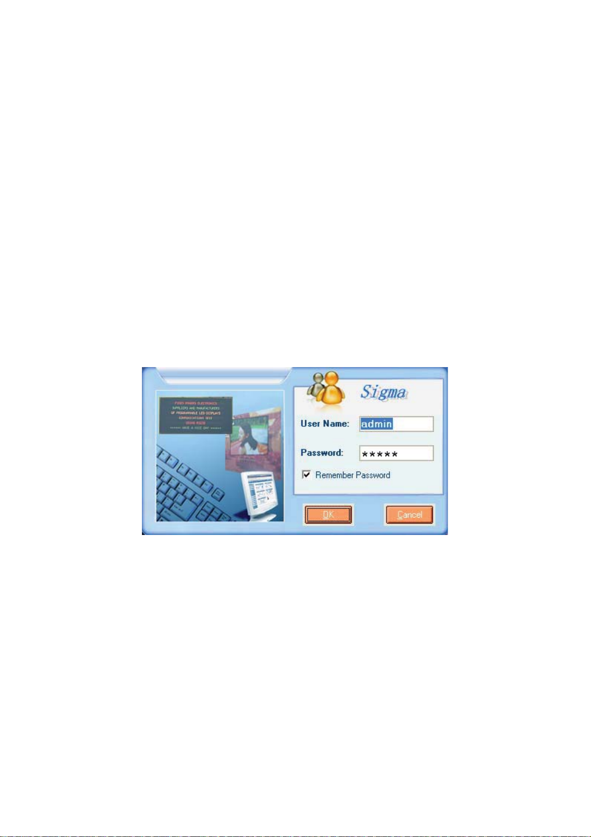
Users will see the following log-in interface whenever they open the software. There are
two default users under the software—The Administrator (short for Admin, with the
password “admin”) and the User (with the password “user”). Only the Admin can update
the sign parameters and change the configurations. General users are allowed just to
do the normal operation, like sending message files or programming the files/pictures.
But a user does not have the right to change any configuration/parameter.
In the following chapters, we will log-in as the Admin and get to know every usage of
Sigma 3000.
Fig. 1.1 The log-in interface
Input User Name and the password, and click OK. The following interface of Sigma
3000 will show up as Fig 1.2 shows.
Page 1 of 98
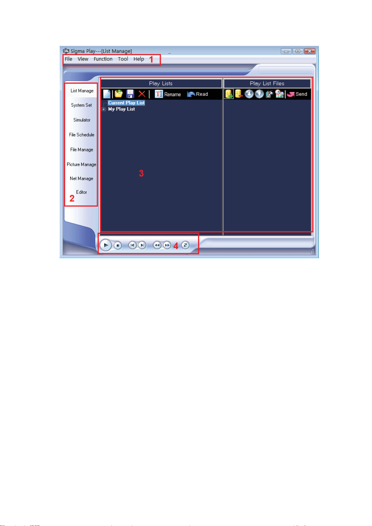
Fig. 1.2 Sigma 3000 Software Interface
As we can see from the above figure, there are 4 main parts that constitute Sigma’s
interface. is the menu bar, where the user can find all tools and functions. is the ķĸ
panel of short-cut keys, where user can realize the setting and send all types of files. Ĺ
is the work area. is the key editing area in Sigma, where all display control buttons ĺ
can be found here.
In the following chapters, we will separately introduce the usage and functions of the
software in Sigma; in chapter 2, we are going to talk about the Sigma Editor; in chapter
3, we will introduce True Font Editor; in Chapter 4, here comes the Font Manager; in
chapter 5, we will know how we can use the tools in Sigma; and in the final chapter 6,
we will tell the usage of the panel of short-cut keys and the rules to follow when using.
System platform˖Windows 95, Windows 98, Windows 2000, Windows XP and Vista
System ˖CPU 500MHz, Memory 64M
Chapter 2 Sigma Editor
Sigma Editor, which has an independent version number, is professional and powerful
software that aims at editing and programming display files. Users can use the Sigma
Editor to send files to the LED sign after editing, or preview the files in the simulator.
With the help of the Sigma Editor, users can insert pictures to the sign, or make the
picture to be the background of other files. What is more, the functions of time
count-down and count-up can also be found in Editor.
Sigma Editor consists of 5 parts: menu bar; tool bar; ķĸĹMode bard; Editing bard; ĺ
Page 2 of 98
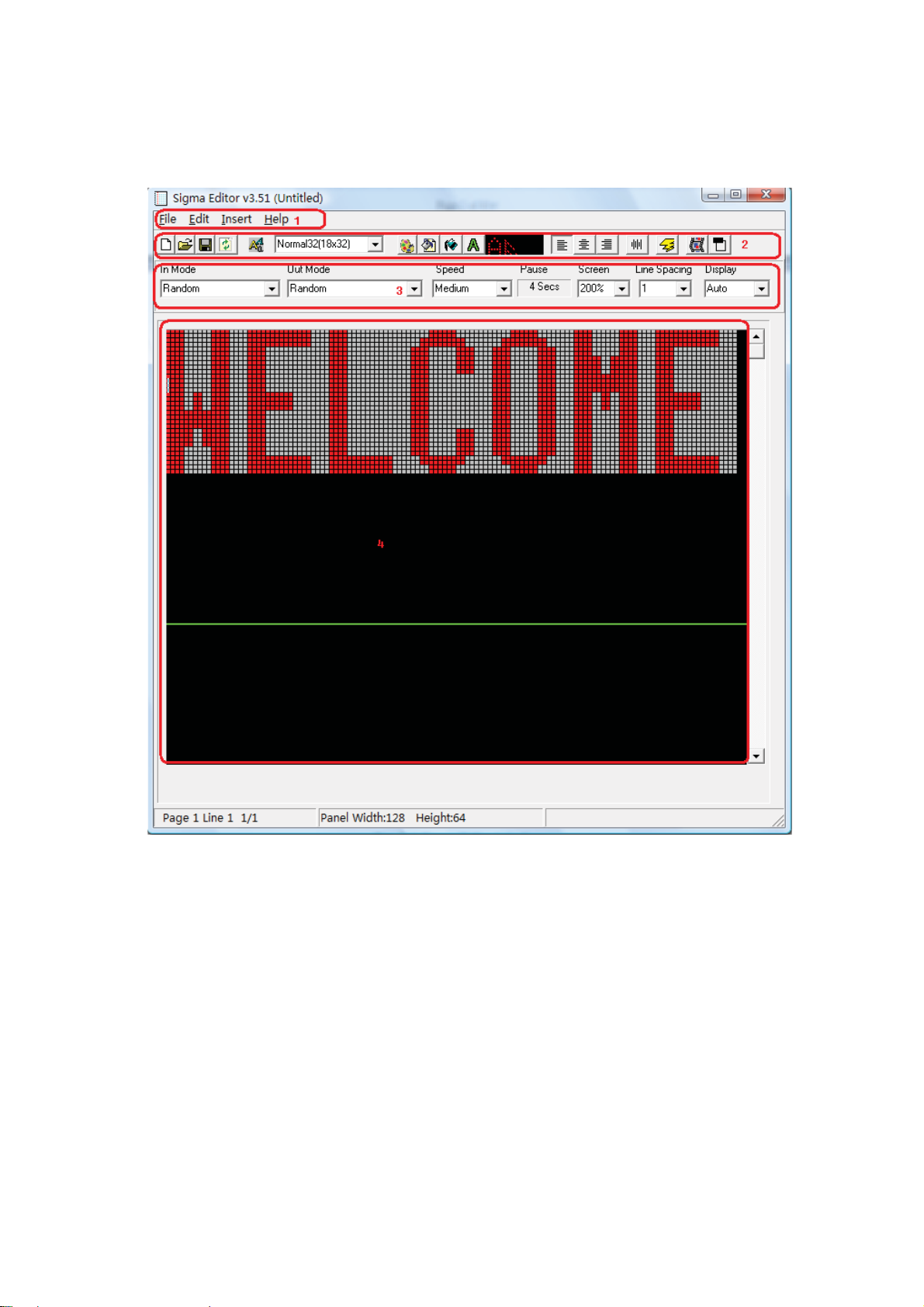
Status bar.Ļ
To open Sigma Editor, users can do the following steps: Open Sigma Play. Click Tools
Æ Edit FileÆ Text File.
Fig. 2.1 Sigma Editor Interface
2.1 Menu Bar
2.1.1 File Menu
As Fig 2.2 shows, there are 8 items under the Menu File.
New: Open a new file;
Open: Open an NMG file;
Save: Save the file;
Save as: Save the file under the name…;
Communicate: The setup information of communicating between the computer and the
sign;
Send to sign: Send the edited files to the sign;
Exit: Exit Sigma Editor.
Page 3 of 98

Fig. 2.2 File Menu Fig. 2.3 Communication Setting
As is seen from Fig 2.3, the communication interface tells us the following information:
current Trans Mode is Ethernet, IP address 169.254.10.160, Port 8887. Group address:
01. Unite address: 01.
(Note: we will refer to the Group Address and the Unite
Address as GGUU in the following chapters. E.g.: 0102 means Group address 01,
Unite Address 02)
Here we need to know what Port, Group address and Unit Address are.
Now let’s get to know what Port is and what port is for first.
What is port?
We can say it in a simple way. Port is the pathway that enables the computer to
communicate with the outside world. Without port, the computer will be both deaf and
mute. Under the Internet language, Port has several meanings. It can refer to the port of
HUB, switchboard or router, like the RJ 45 COM PORT, SERIAL COM PORT. When we
are talking about the PORT here, we are not talking about its or dinary physical meaning;
we are talking about its logical meaning. Here Port refers to the port in the TCP/IP
protocol.
Then what is Port referring to under the TCP/ IP protocol?
Let’s say, we take the IP address as a house, then Port is the door of the house. Usually,
a real house can have no more than 10 doors, but for the IP address house, it can have
65536 doors. That is 65536 ports. Generally, we will mark these ports by the port serial
numbers, ranging from 0~65536.
What is port for?
As we know, a host comp uter can provide us many services—Web service, FTP, SMTP
etc. All those services can be realized though one IP address. Then how can the host
computer distinguish these different services? Apparently, using one IP address only is
impossible to realize so many services, because IP address and these services is not a
biunique relationship. In fact, the host computer distinguishes these services by “IP
address + Port serial number”.
As it is noticed to all of us, the Ports are not counterpart. For example, a user is visiting
a WWW service as a client computer. WWW service is using Port “80” to communicate
Page 4 of 98

with the user’s computer though Port “3457”, as Fig 2.4 shows. That is to say, WWW
service does not need to communicate with Port “80” in the user’s computer.
Fig. 2.4
Under the definition of counterpart protocol type, there are two types of Ports: TCP Port
and UDP Port. These two types of Ports are mutually independent, because the
protocols of TCP and UDP are separate. These two types of Ports do not have conflicts.
Either TCP or UDP has 235 Ports.
How do the Ports allocate?
Same as the IP address, we do not use Port randomly. When we allocate them, we are
following certain rules. There are several types of Ports according to classification
standard. Here would not explain all of the classifications in detail but the Well Known
Ports and the Dynamic Ports.
1. Well Known Ports
As the terms explains, Well Known Ports refer to the Ports that are known to all of us,
ranging from 0~1023. For example, when we type www.cce.com.ce in the address bar
of IE, we do not need to point out the Port series number. Usually, the default Port of
WWW service is “80”.
The web service can use other Ports to provide the service. If it is not the default Port
series number that is used, users should input the appointed Port series number in IE’
address bar. That is to say, users should add a COLON “:” (Semi-angel) + Port series
number in the end of the address bar. Here is an example; we will use “8080” as the
port of WWW service. In this case, we need to input “www.gonetn8.com
gonet8.com:8080”.
Please note that some of the Ports are fixed under certain protocols. They are not
allowed to be changed manually. For example, Port 139 is fixed for the
communication between NetBIOS and TCP/IP.
2. Dynamic Ports
Dynamic Ports range from 1024~65535. Those Dynamic Ports are not fixed for any
certain service. They are dynamically allocated. Dynamic allocation means those ports
are temporary applied from the host computer. Let’ s say, now there is a system program
or application program that is performing the network communication. Under such
circumstance, the program will apply a Port from the host computer. Then the host
computer allocates one Port to the program, and once the program is shutdown, the
Port will be released.
Now we can have a general idea of what Port is and what Port is for. Here Fig 2.5
shows how the Ports are used in an LED sign.
Page 5 of 98
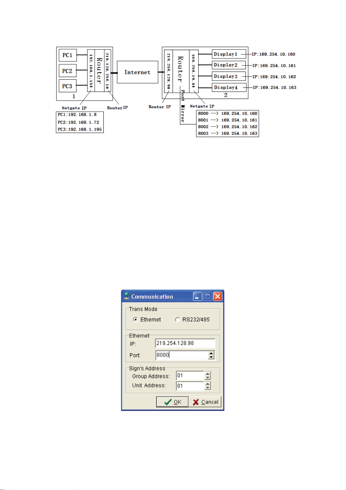
Fig. 2.5 Drawing of the Port interface
As we can read from Fig 2.5, in inner-Net 2, 219.128.254.98 is the IP address of the
router. 169.254.19.84 is the IP address of the gateway. From the figure, we can see
that in Inner-Net 2, there are 4 dynamic ports –8000~8003, corresponding to the related
IP: 169.254.10.160169.254.10.163 .
How can we control Sign 1 though PC1 in Inner-Net 1? Apparently, if we just input
169.254.10.160 to the interface of Fig 2.3, we will not be able to program Sign 1 by PC
1. Under such circumstance, we need to introduce an outside net in to connect the two
inner-nets.
So in Fig. 2.3, instead of inputting the IP address 169.254.10.160, we should input the
IP address of the router in Inner-Net 2----19.128.254.98, with the Port 8000 if we would
like to program Sign 1. If it is Sign 2 that we want, then we should input Port 8001. And
so on for Sign 3 and sign 4. Only the IP address of the router in Inner-Net 2 is
unchanged.
Here Fig.2.6 shows the setting of communicating Sign A with PC 1.
Fig. 2.6 Communication through an outside net
Now let’s get to know more about Group Address and Unit Address. As we explained in
the last chapter before, GG stands for Group Address, while UU stands for Unite
Address. With the help of GGUU, we can communicate with 99x99 LED signs.
Please note that 0000 means the broadcast address. If we are searching for one certain
Page 6 of 98
LED sign, we can use the broadcast address to communicate with other GGUU.
GGUU is meaningful to our management of the LED signs. For example, we can set up
the signs in the workshop as a group. In this case, all the signs in the workshop are with
the GG “01”. Every LED sign is a separate unit, with the UU ranging from 01~99. What
is more, we can set all the signs in the office as group 2, with GG 02, and different UU to
communicate with.
Under such circumstance, we can manage all the signs according to different groups.
Even with the same IP address, we can still tell the signs apart from the different
GGUU.
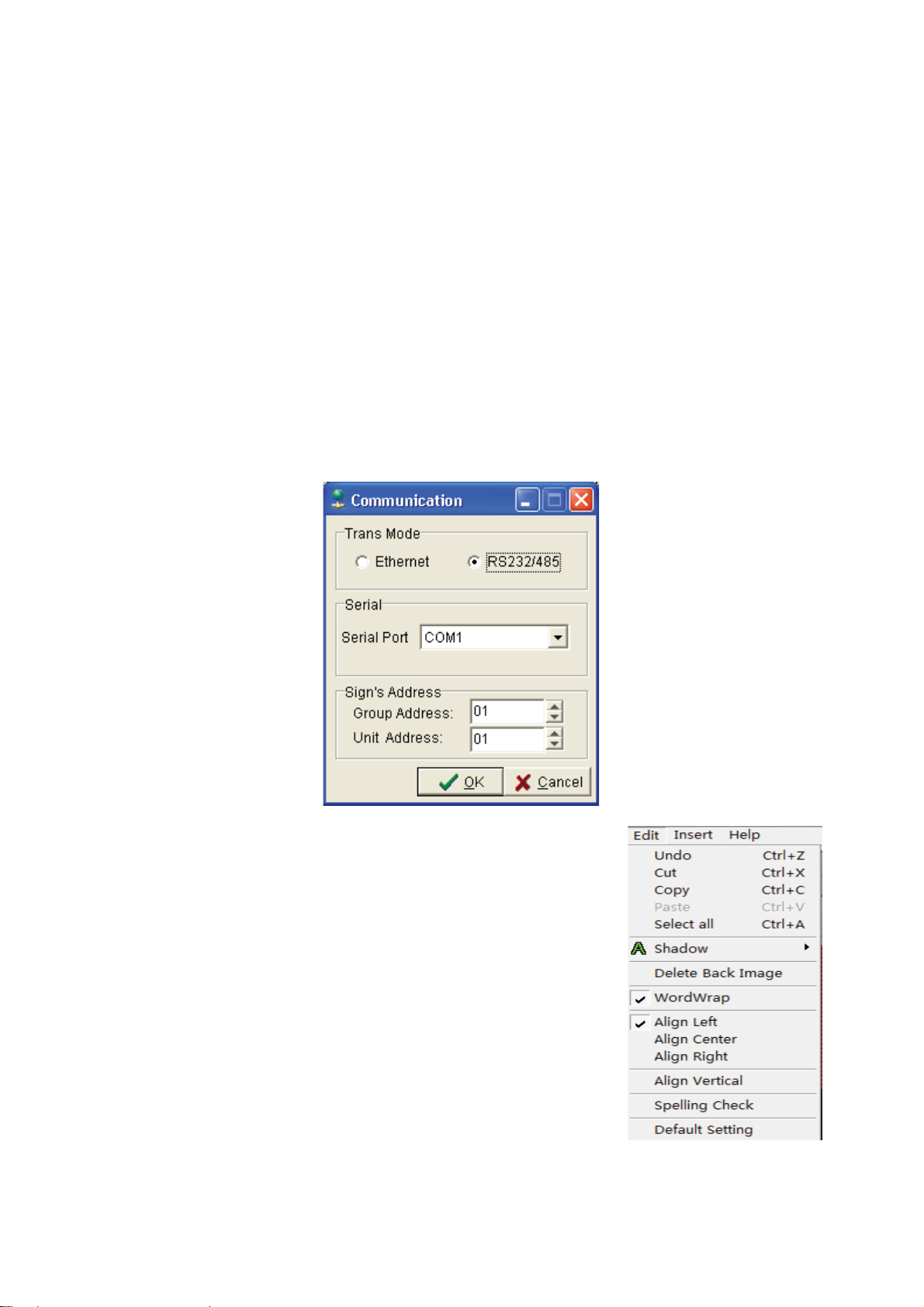
The other Trans Mode is serial port. As shown in Fig 2.7, Serial Port refers to COM 1 in
the computer, with GGUU 0101.
Sigma Play will check the Baud rate of the sign if Serial Port is used for the 1
communicating interface will disappear once the Serial Port receives the data back from
the sign, which means communication succeeds. Otherwise the software will tell that
communication failed.
st
time. The
Fig. 2.7 Serial Port Interface
2.1.2 Edit Menu
As show in Fig 2.8, most of the function is the same as
the tool bar.
Undo: Cancel the last operation
Cut: Cut chosen text or graphics in the editing area
Copy: Copy the chosen text or graphics in the editing area
Paste: Paste the chosen text or graphics to the editing area
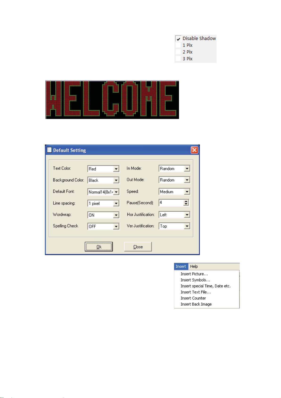
shadow˖You can add a box around a character
or some characters, but you cannot see the box unless in
simulator or display mode. The display effect is as in A1˖
Select All: Choose all the content in the editing area
Delete Back Image: Delete the background picture in the Fig. 2.8 Edit Menu
editing file.
Word Wrap: Automatic line-change
Page 7 of 98
Align Left: Text align left horizontally
Align Center: Text align center horizontally
Align right: Text align right horizontally
Align Vertical: Text align center vertically
Spell Check: Checking the spelling of words
Default setting: The default editing mode in Sigma Editor
Fig.A1
The following Fig 2.9 shows the interface of default setting. We can see that there are
12 default settings in the figure. Press OK, Sigma Editor will follow those default
settings when a new file is opened for editing.
Fig. 2.9 Default Display Setting Interface
2.1.3 Insert Menu
From Fig 2.10, we can see that there are 6 options
under Insert Menu. Here we will introduce the functions
of these 6 options.
Insert Picture: Users can insert the picture (BMP format) to the editing area, as Fig
2.1 1 shows. Choose one BMP file, click OPEN. The BMP file will be added to the editing
area. Users can send the file to the sign.
Page 8 of 98
Fig. 2.10 Insert

Fig. 2.11 Insert a picture
Fig. 2.12A
Fig. 2.12B Picture in the Editing area
As can be seen in Figure 2.11, if the inserted picture is larger in size than the size of the
LED screen, you will see a prompt asking you whether you want to stretch the picture
size to the LED screen size. If you press Yes, you will see the picture in Figure2.12B.
Insert Symbols: This function helps the user to insert some special symbols whenever
they need. Sometime we find that it is not that convenient to insert some special
symbols, because they can’t be found on the keyboard. That is why we need the
function of “Insert Symbols”. As shown in Fig 2.13, we can see the special symbols
and characters of font Normal130. The symbols and the characters vary with different
types of fonts.
Page 9 of 98
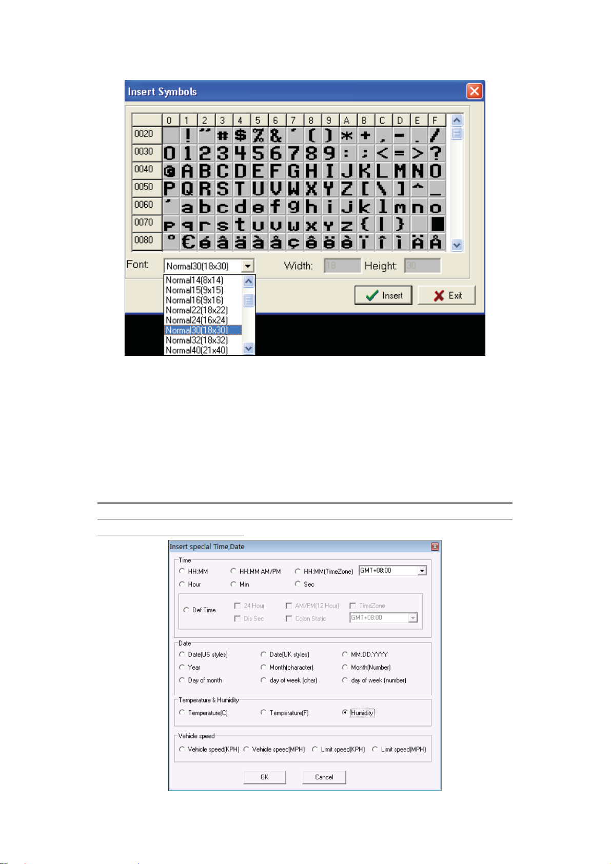
Fig. 2.13 Insert Symbols Interface
Insert Special Time, Date, etc.
With this function, users are able to insert time of different world time zones,
temperature, date, week, and humidity to the sign. Before inserting any time and date,
we should correct the time of the sign with the computer’s first, otherwise we might think
that there were some problem with the time. Before we insert humidity and temperature,
we also need to be sure that we already have the humidity and temperature sensor.
Otherwise, humidity and temperature will be shown as NA on the sign.
Special note: Even with the temperature and humidity sensor, when we insert temp &
humidity, it would be shown as NA in the editing area, but this would not affect the
information shown on the sign.
Fig. 2.14 Interface of inserting Time, date
Page 10 of 98
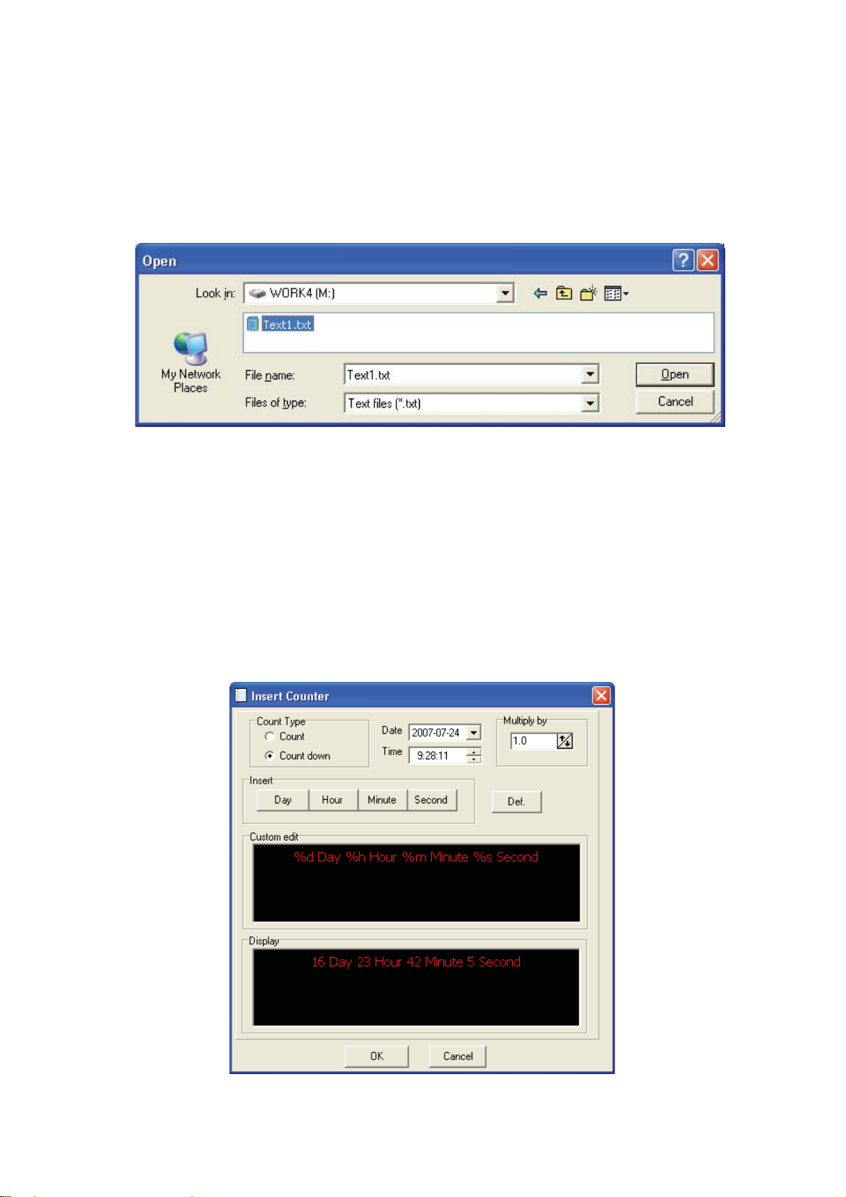
Insert Text File: This function enables the user to insert the txt. File directly without
inputting any message again to the editing area. Sigma Editor will paste the txt. File
directly to the editing area once the file is chosen. This function accelerates the
programming speed and reduces the inconvenience during programming.
As shown in Fig 2.15, click Open to choose the txt. File that we want.
Fig. 2.15 Interface of inserting txt. File
Insert Counter: With this function, users will be able to insert a counter, either
down-counter or up-counter. From Fig 2.16, we can see that in the counter interface, we
can count either time or objects. The coefficient of correlation rang from 0.1~999. We
can notice that there are two count types—counting up and counting down. We can
also choose to count by days, hours, or by seconds. Or we can choose to input %d(%of
days), %h(% of hours ), %s ( % of seconds) directly to the editing area.
What is coefficient of correlation?
For example, we set the coefficient as 100. If we would like to count down for 2 days
time, the coefficient will multiply the number, which makes 200. Only till the days
remains 1 day left then it makes the outcome 100.
Insert Back Image
Fig. 2.16 Insert counter interface
Page 11 of 98
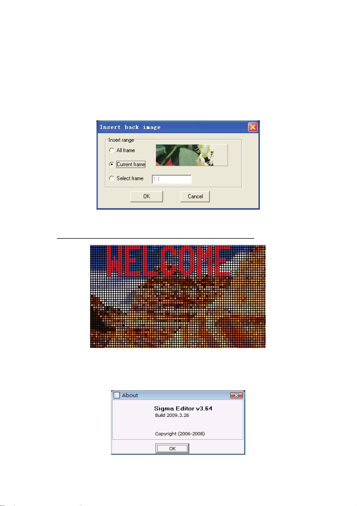
With this function, users can find it convenient to edit and program the file with both text
and graphic. With this function, user is able to program the same content to every frame,
or set different background picture in each frame. Or users can even edit some text
suspending above the picture.
Here is an example, as shown in Fig 2.17. We now would like to choose one picture
(BMP file) as the background. We will see an interface asking us if we would like to set
for “All frame”, “Current frame” or “Select frame”. After we select the function that we
want, we can add some text to the back ground.
Fig. 2.17 Insert Back Image Interface
From Fig 2.18, we can see the effect of a file which is added with some text.
Special note: Only one display mode is available for the test that insert.
Fig. 2.18 Back-ground picture with text
2.1.4 Help Menu
In the Help Menu, we can find the version number of Sigma Editor, as Fig 2.19 shows.
Fig. 2.19 About Sigma Editor
Page 12 of 98
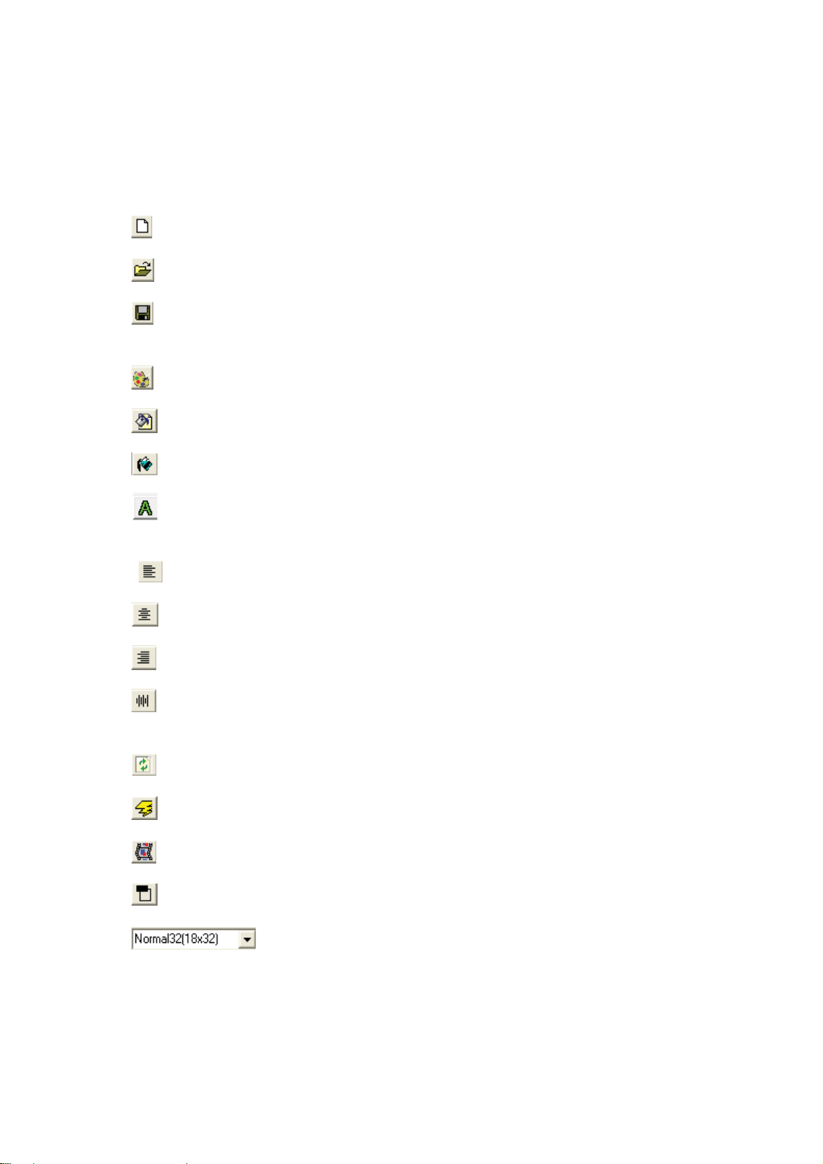
2.2 Tool Bar
There are several types of tools in Tool Bar: File tool, Color tool, Align tool and
other tool. Here we are going to introduce the usage of these several types of tools.
File Tools
: Open a new NMG file˗
: Open the NMG files˗
: Save the file˗
Color Tools
: Palette of the font color˗
: Back-ground palette of fonts˗
: Back-ground palette of frame˗
˖Shadow˗
Align Tools
: Horizontal left align˗
: Horizontal center align˗
: Horizontal right align˗
: Vertical center align˗
Other Tools
: Short cut key for sending files˗
: Set flashing feature for a certain character or picture˗
: Simulated display, as Fig 2.20 shows˗
: Insert a title, as Fig 2.21 shows˗
: choose the font type.
Page 13 of 98
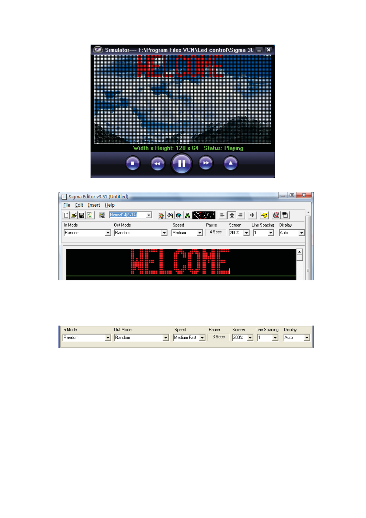
Fig. 2.20 Simulated display
Fig. 2.21 Insert a title
2.3 Mode Bar
Fig 2.22 shows the Mode Selecting Bar in the Editor
Fig. 2.22 Mode Bar
In mode: The display mode of a file when it goes into the sign
Out mode: The display mode of a file when it goes out of the sign.
Speed: Display speed of each frame
Pause: Pause/hold time of each frame. Fig 2.23 shows the interface of Set Hold time.
We can see that the pause time of the in-mode can also be included. That is the pause
time = in mode time + out mode time.
Page 14 of 98
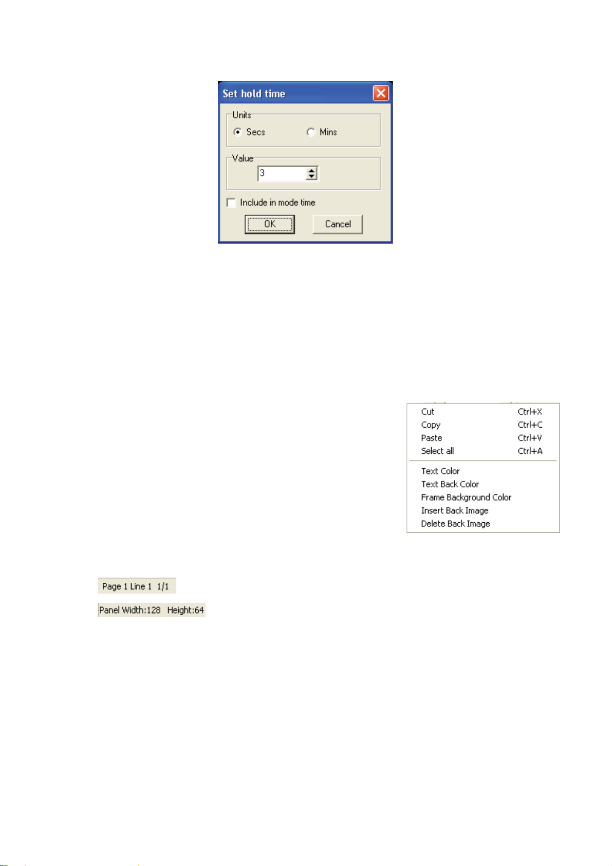
Fig. 2.23 Set hold time
Zooming: If the sign is too large, we can zoom the editing area in order to make the
program more convenient.
Line Space: Users can set the space of between 2 lines, with the Max value 9 and Min
value 0. The unit of the line space is by pixel.
Display mode: Only Jump out and chasing mode is available.
2.4 Editing Area
The Editing Area provides the users a platform to edit
the files and display the message. Users can perform
the operation like inserting picture, time, temperature,
humidity, text files, counter down and counter up etc. All
files that saved will be with the suffix name of NMG.
If we click the right key, we will see a Right-key menu,
as it is shown in Fig 2.24. We have introduced these
functions in the previous parts. This menu makes the
program more convenient and quicker.
2.5 Status Bar
Status Bar indicates the current information of the current editing file. For example:
means the current editing page and the position of the cursor.
indicates that the current editing file can be used for the sign
with 64 pixels height and 128 pixels wide.
Page 15 of 98
Fig. 2.24 Shortcut Menu
Chapter 3 True Font Editor
True Font Editor is a kind of editing tool for editing dot matrix files. The most obvious
advantage is that it can edit any font in the computer system and show them on the LED
display without downloading font list onto the display.
Fig 3.1 shows the process of opening
the True Font Editor.
Choose ToolÆEdit fileÆTrue Font file.
Fig 3.1 Choose dot matrix
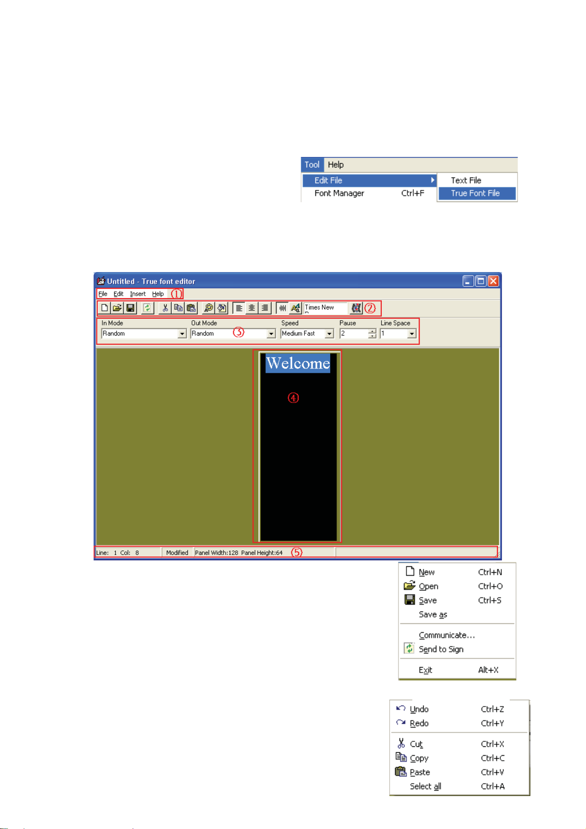
As Fig 3.2 illustrates, True Font Editor has the same layout as Sigma Editor. 1--- Menu
Bar, 2---Tool Bar, 3---Mode Bar, 4---Edit Area, and 5---Status Bar. The following is the
introduction of their functions.
Fig. 3.2 True Font Editor Interface
3.1 Menu Bar
3.1.1 File Menu
Fig 3.3 shows the pull-down menu of File Menu, which has the
same functions as Sigma Editor. Please refer to the above Sigma
Editor for more information about Communicate setting and
Send to sign.
3.1.2 Edit Menu
Fig 3.4 is the pull-down menu of Edit Menu. Since it is simple,
it is quite easy to understand.
Page 16 of 98
Fig. 3.3 File Menu
LED Sign
3.1.3 Insert Menu
The Insert Menu has only one function--inserting pictures to edit area. The picture
format it supports are: BMPǃJPGǃJPEG and ICO. Y ou can pull the pictures randomly to
change their sizes.
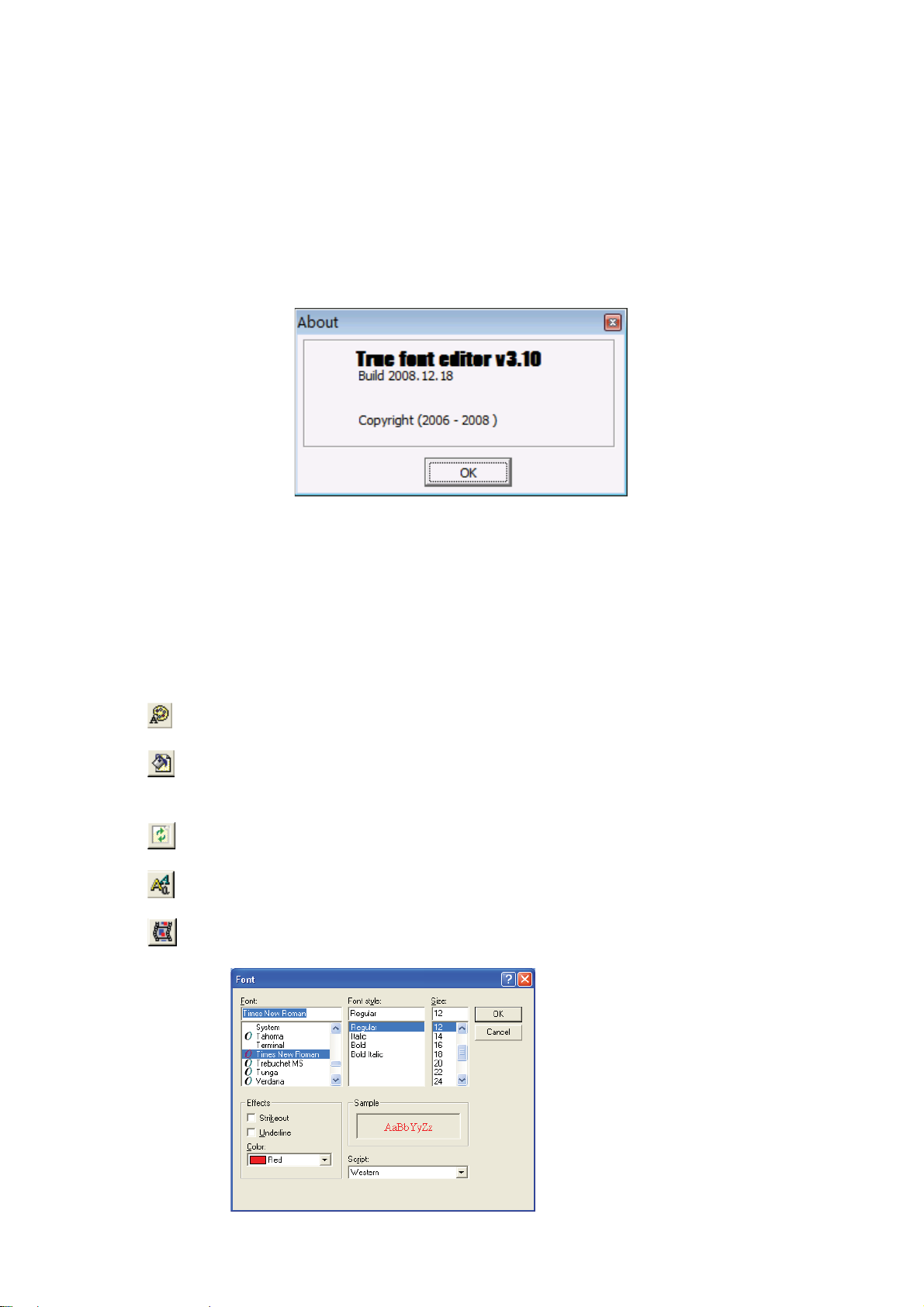
3.1.4 Help Menu
The Help Menu has only the version information about True Font Editor. See Fig 3.5.
Fig. 3.5 Version information about True Font Editor
3.2 Tool Bar
Tool Bar of True Font Editor can be divided into file tool, color tool, alignment tool and
other tools. All the tools in True Font Editor have almost the same function as those in
Sigma Editor except that True Font Editor doesn’t have frame back-ground color and
the button of headline choice.
Color tools:
: Foreground colors of characters
: Background color of characters
Other tools:
: Sending button, the same as Sigma Editor
: Font choosing tool, supporting fonts in the PC system
: Simulating button, the same as Sigma Editor
Page 17 of 98
Fig 3.6 Font choosing
3.3 Mode Bar
ging
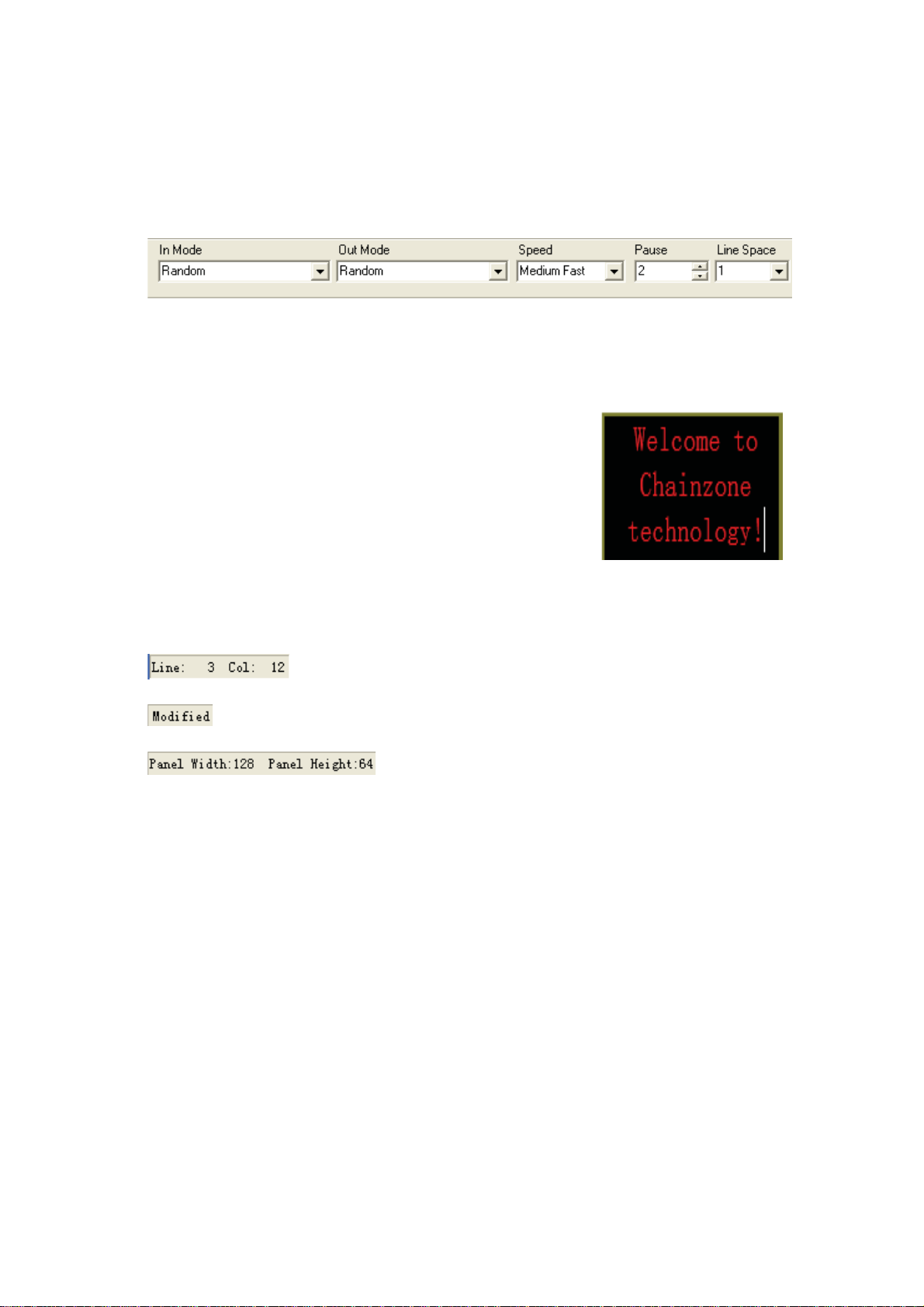
From Fig 3.7 we can see that the setting modes and their related functions are the
same as Sigma Editor’s, which include in mode, out mode, speed, pause and line
spacing. The only difference lies in the display time.
Fig. 3.7 Mode Bar
3.4 Editing Area
Different from Sigma Editor, True Font Editor doesn’t
regulate the boundary line to separate the editing information frame by frame. In the area, lines can be changed
automatically. The same as table editing in Word file, it
can enter another line to show a complete word. See Fig
3.8, if the words
matically, then there will come several letters following
behind
changing, there will come space of each line.
Chainzone. Thus, due to the automatic line
technology doesn’t enter lines auto-
Fig. 3.8 Automatic line
chan
.
3.5 Status Bar
: The location of the cursor, in which line and which column
: In the status of editing information
: Size of panel, width: 128, height: 64.
Chapter 4 Font Manager
As Fig 4.1 shows, press Tool and then Font Manager to open the Font Manager
software.
Fig 4.2 is the interface of Font Manager, which is mainly made up of five parts:
1---Menu Bar, 2---Tool Bar, 3---Font List Bar, 4---Shortcut Button, The following is their
detailed functions.
Page 18 of 98
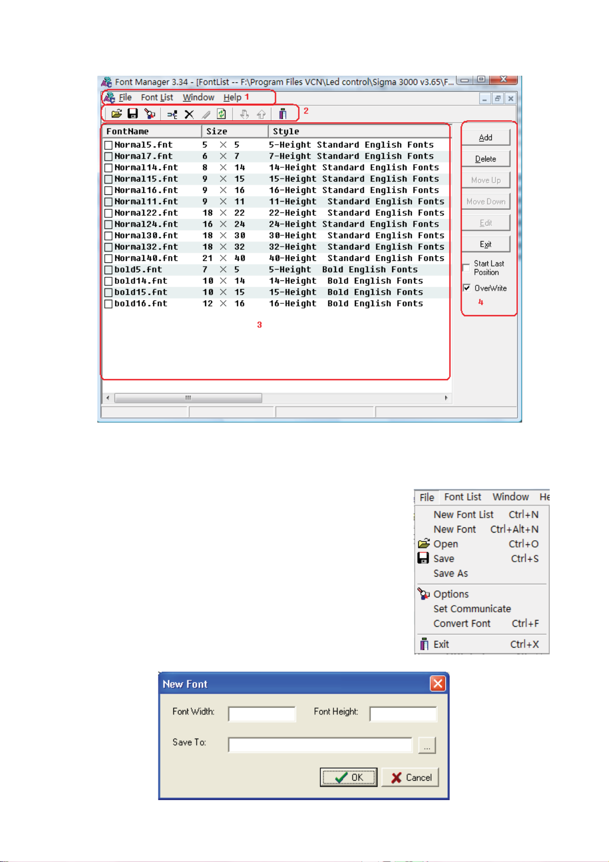
Fig. 4.2 Font Manager Interface
4.1 Menu Bar
4.1.1 File Menu
Fig 4.3 illustrates the pull-down menu of File Menu.
We will focus on some special functions.
New Font: It means a customized font based on user’s special
need and preference. Fig 4.4 is the interface of establishing new
font. Set the height and width of the font you want, and then
choose the saving path, you can create your own fonts now.
Suppose you want a font of 10dots height and 7 dots width, just
input the related information, choose saving path, and press button Fig. 4.3 File
Menu
OK. Fig 4.5 is the interface of customized font.
Page 19 of 98
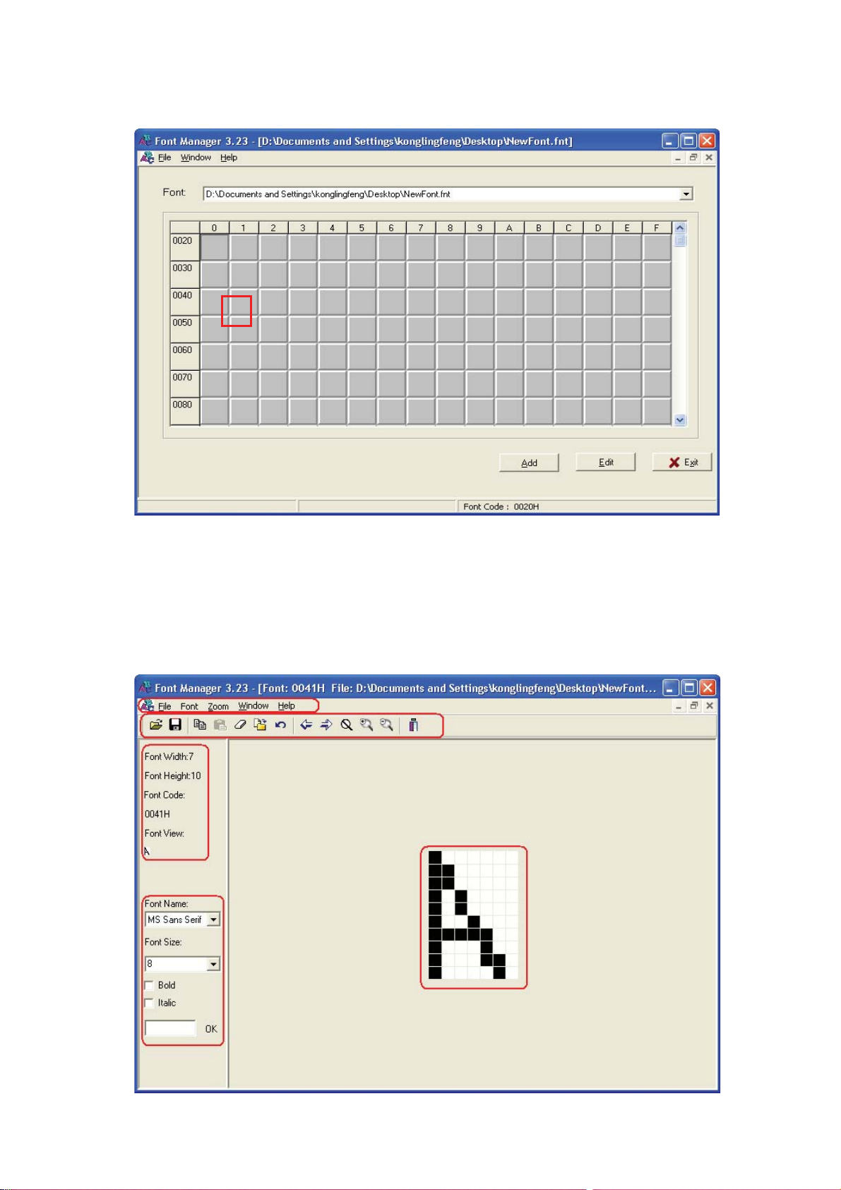
Fig 4.4 New font interface
41
Fig 4.5 Interface of customized font
There is a ruler of line and column in Fig 4.5. Actually it is the ASCII location of each
font you are creating. So the fonts should be established in accordance with ASCII
principle, otherwise you won’t get what you want through the input on the keyboard. In
ASCII code, the big letter A is at 0041(hexadecimal), so we can make a big letter A just
at this place. Double click the place of 0041, there will appear an editing interface like
Fig 4.6.
Fig 4.6 Font editing interface
Page 20 of 98
From Fig 4.6 we learn that the editing area is made up of 5 parts, 1--- Menu Bar,
2---Tool Bar, 3---Character Information, 4---System Font, 5---Font Editing Area.
Notes:
Menu Bar, Tool Bar are bonded together with the Font Manager, only partial functions
belong to this edit interface.
Area 3 shows the character information: font—10*7, ASCII code—0041H (H represents
Hexadecimal)
System font means users can create any fonts on the base of the current fonts in the
computer system. Press button OK after choosing a kind of font and you can download
the system font into the font editing area.
Font editing area: Click the left key of the mouse, the block will turn to black, and click
the right key, the block turns to white.
After editing your own font, you should save it and then exit.
Font Style: It is the tool to examine a certain font style in the font list. Fig 4.7 discloses
the way.
First choose a kind of font, Normal15, for example, and then choose the font style. Via
the following figure, we know that the font style is 15*8 Standard English Fonts. The
moment font style changes, the nature of the font varies. So we only recommend
checking here, no modification.
Fig 4.7 Font Style
For example˖
Suppose we want to switch to Arial Font 16. We will open the font conversion dialogue
as shown in Fig 4.7. We select a font and size, and then a path to save the file. Then we
select a language. Finally, we press the button
progress bar changing, and the button
conversion is completed and you will see Figure 4.8, with the font file name being
Arial16.FNT. You can add it to the font library and send it to the LED screen.
Page 21 of 98
changes to . The
and we will see the
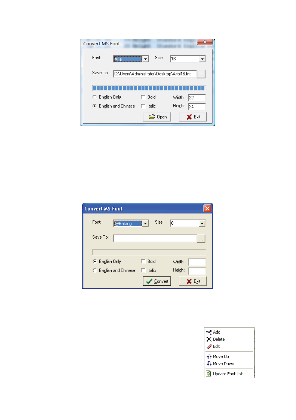
Figure 4.8 Conversion completed
Communication setting: Consult the counterpart in Chapter 2 Sigma Editor.
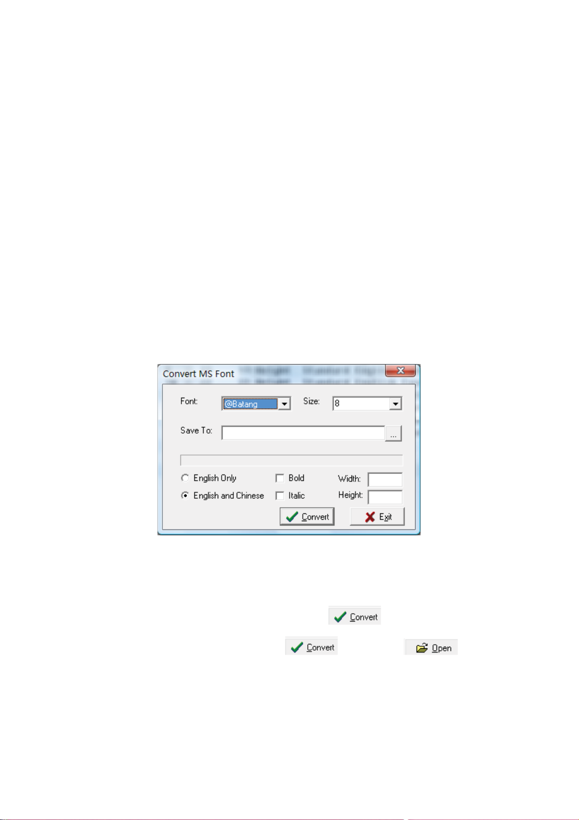
Font Conversion: The function of this tool is to convert the font to be a FNT
format one in Font Manager which can be downloaded to the display. See Fig 4.8, the
converting interface. Choose a fixed font and size you want to change, and set the
saving path and the font size you want, press Convert button, then you can realize this
function.
Fig 4.8 Font Converting Interface
4.1.2 Font List Menu
See Fig 4.9, the pull down menu of font list menu, we will introduce
the functions and meanings.
Add: Add new font to the font list.
Delete: Delete font from the font list.
Edit: Edit the font in the font list.
Move Up: Move the chosen font up.
Move Down: Move the chosen font down.
Update Font List: Send the font list to the display.
Page 22 of 98
Fig. 4.9 Font List Menu
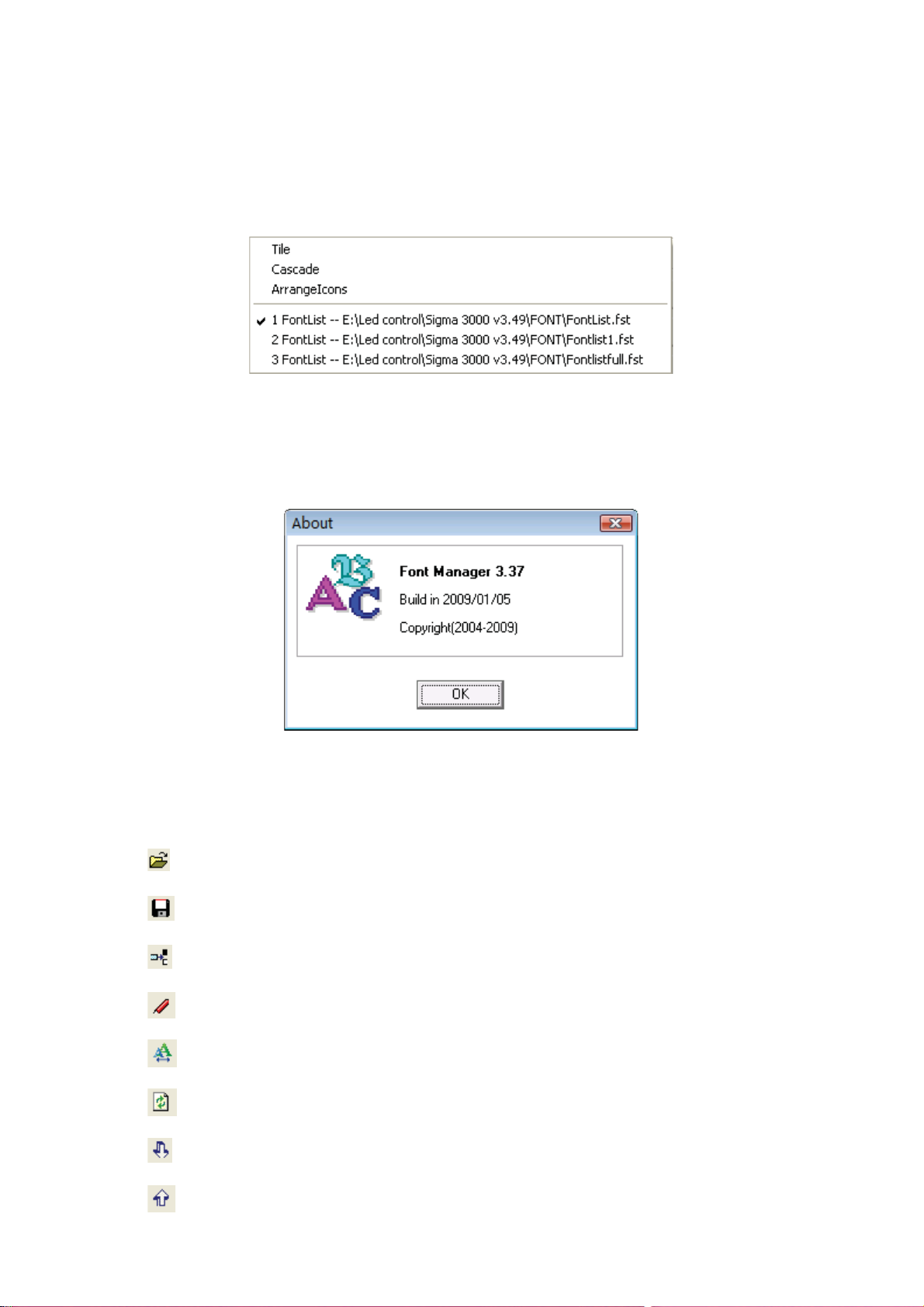
4.1.3 Window Menu
As Fig 4.10 shows, in the window menu, there are three functions: tile, cascade, and
arrange icons. The following is the window converting bar of the open font list. The
current chosen item is the first font list.
Fig 4.10 Window Menu
4.1.4 Help Menu
As Fig 4.11 shows, the help menu mainly gives the version information of Font
Manager.
Fig 4.11 About Font Manager
4.2 Tool Bar
The buttons here are the same as the ones in Menu bar.
: Open the font list file.
: Save the font list.
: Add the font to the font list.
: Edit the font in the font list.
: Examine the font style.
: Update the font list to the display
: Move down the chosen font.
: Move up the chosen font.
Page 23 of 98
: Exit from the Font Manager.
4.3 Font List Bar
Font list area shows the fonts users have added. If you want to
send some fonts to the display, you need to add those fonts to the
list. There is a right key menu of the font list bar. See Fig 4.12. The
function is the same as those pull down menu of the main menu.
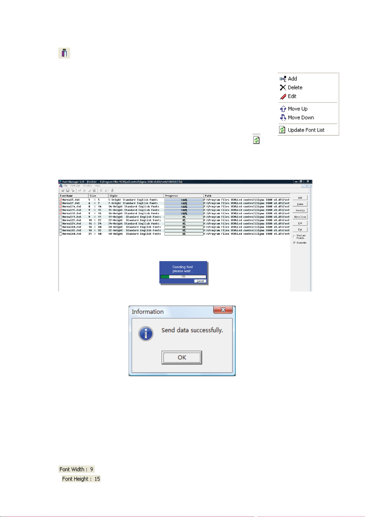
Suppose we want to send the font file Normal5-40 to the LED screen. We
first add Normal5.fnt~Normal40.fnt to the font library. Then we click
and we will see a communication interface. We select a mode that is workable for the
LED screen, press the button OK, and we will see the progress bar moving towards
100%. If the data is sent, we will see the figures 4.13 and 4.14.
Figure 4.13 Font library being sent.
Fig. 4.12 Shortcut Menu
Figure 4.14 Data sent successfully
4.4 Shortcut Button
It is the repetition of the font list pull down menu. Being placed at the right side, users
can use it quickly.
4.5 Status Bar
Status bar gives related information with the chosen font.
˖Width of the font is 9 dots.
˖Height of the font is 15 dots.
Page 24 of 98
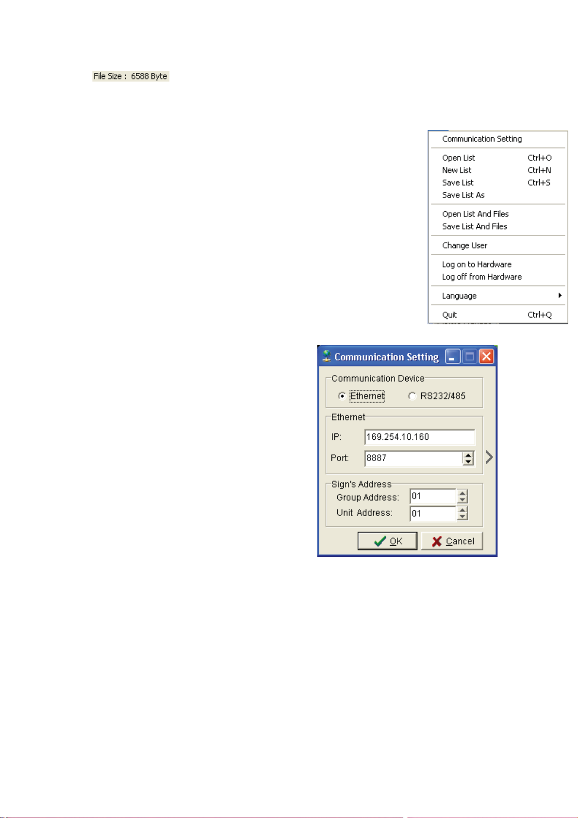
˖ Size of the font is 6588 byte. (About 6k).
˚
Chapter 5 Tools of Sigma Software
In the first chapter we have divided the Sigma Software interface to four
parts, Menu Bar, Shortcut Panel, Work Station and Play Controller. We
will focus on Menu Bar’s function in this chapter.
5.1 File Menu
Fig 5.1 shows the pull down menu list of Sigma Play File
Menu.
5.1.1 Communication Setting
Fig 5.2 is communication setting interface which is the
same as the counterpart in chapter 2 in function except a
quick connection function.
Press the expansion button
connection displays. These items are searched
in the Net Manager. Only those displays that can
be searched in the Net Manager can be connected quickly. As Fig 5.3 shows, there are three
displays to be chosen from the connection list.
Choose any one and you can realize the communication with it.
If the display is found by Ethernet in Net
Manage, then the display will be connected by
network when connecting rapidly. If it is found
by serial port, then it will be connected via
serial port.
When connecting quickly, the related information about the display will be recorded
automatically.
So once the GGUU or IP address or other correlated information about the
communication changes, the seeking have to be executed once again. Or the quick
connection will fail.
to open the
Fig. 5.2 Communication Setting
Fig. 5.1 File Menu
Page 25 of 98
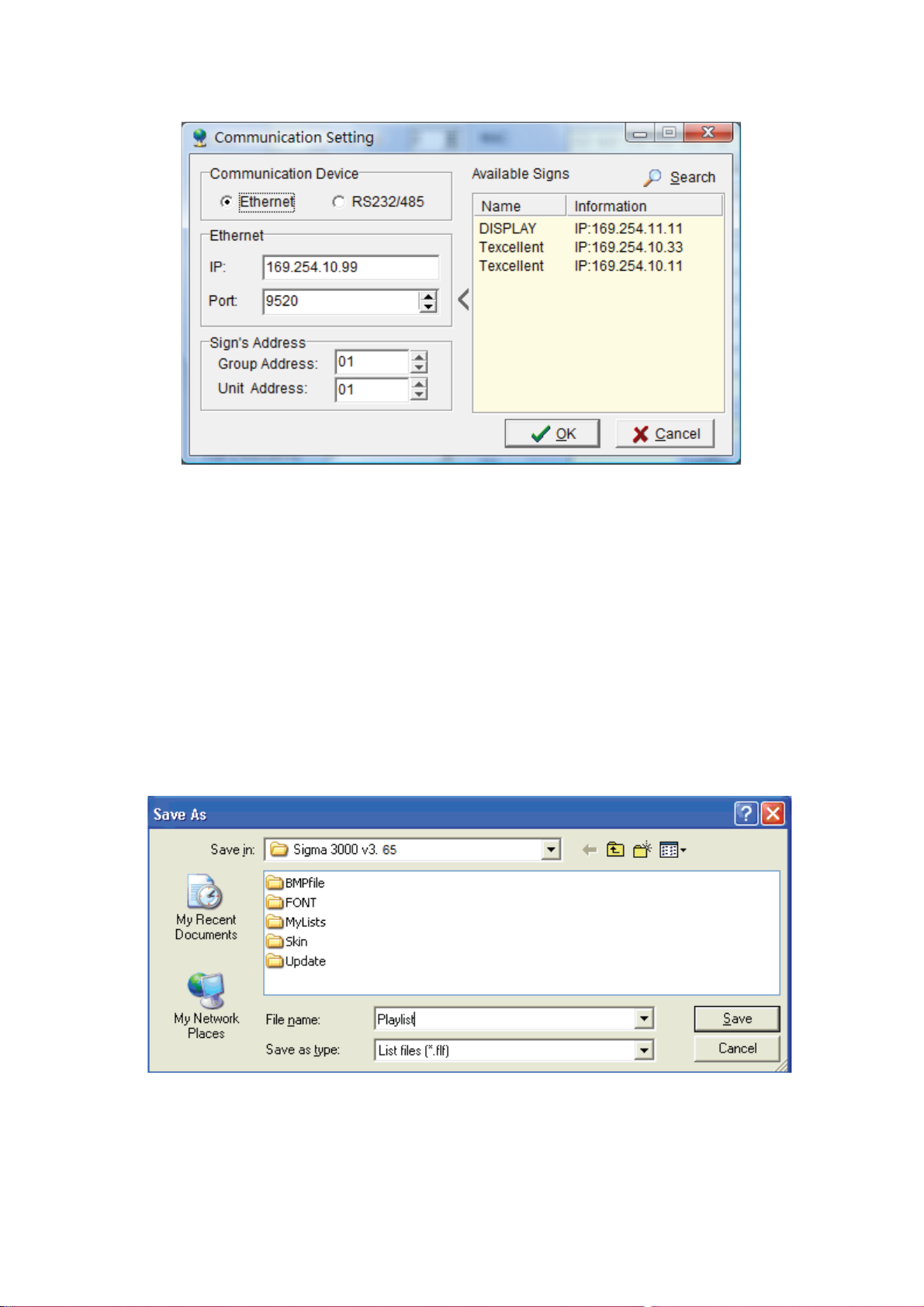
Fig. 5.3 Quick Connection Setting
5.1.2 Operation of Play List
There are six operating functions about the play list in the file menu. They are: New
Play List, Open Play list, Save Play List, Save the Play List as, Open the List File
Package, and Save List as well as File in a Package.
The final function means you can make a package for the chosen play list and its files in
order to make the saving convenient. So you can open the list file package to open it
when use next time. If you like, you can send it to other users to avoid unnecessary
trouble.
See Fig 5.4. When packing the play list and files into a package, there will popup a save
as window. Input Play-list in the file name bar and then press the Save button you can
finish packing the play list with format flf.
Fig 5.4 Packing play list
Note: Only after choosing a play list can you save the list and file in a package.
5.1.3 Change user
Fig 5.5 is the login interface from which you can change login users. The following
table shows the login way.
Page 26 of 98

Fig 5.5 Login interface
User rank User name Password
Manager admin admin
Ordinary user user user
5.1.4 Log on to Hardware
The login hardware mainly includes log on to hardware and logout. The function can be
set in the System Set panel. Once set, you have to choose Login on to Hardware to
communicate with the display hardware. In this way, you can avoid the parameter
changing by unprofessional persons or some illegal operations.
Fig 5.6 illustrates the login interface. The default user name is administrator and default
password 000000. Press OK, and the login is successful. See Fig 5.7.
Fig 5.6 Login on to hardware Fig 5.7 Login successfully
5.1.5 Others Operations
The last two items about the file menu is language and exit.
Only English and Chinese is available.
5.2 Function Menu
Fig 5.8 is the pull-down menu of function
menu. We will divide them to several parts and
introduce them one by one.
Page 27 of 98
Fig. 5.8 Function Menu
 Loading...