

Euro-Line AWR518/522HL, AER518SH3, FCR518/522HL, AER522SH3 Technical Data & Service Manual

TECHNICAL DATA & SERVICE MANUAL
Indoor Unit Outdoor Unit
AWR518/522HL AER518SH3
FCR518/522HL AER522SH3
SPLIT SYSTEM AIR CONDITIONER
AER518SH3
AER522SH3
AWR518/522HL
FCR518/522HL
0.8180.144.0 02/2001
®

i
Important!
Please Read Before Starting
This air conditioning system meets strict safety and
operating standards. As the installer or service person,
it is an important part of your job to install or service the
system so it operates safely and efficiently.
For safe installation and trouble-free operation, you
must:
●Carefully read this instruction booklet before
beginning.
●Follow each installation or repair step exactly as
shown.
●Observe all local, state, and national electrical codes.
●Pay close attention to all warning and caution notices
given in this manual.
This symbol refers to a hazard or
unsafe practice which can result
in severe personal injury or
death.
This symbol refers to a hazard or
unsafe practice which can result
in personal injury or product or
property damage.
If Necessary, Get Help
These instructions are all you need for most installation
sites and maintenance conditions. If you require help
for a special problem, contact our sales/service outlet
or your certified dealer for additional instructions.
In Case of Improper Installation
The manufacturer shall in no way be responsible for
improper installation or maintenance service, including
failure to follow the instructions in this document.
Special Precautions
When Wiring
ELECTRICAL SHOCK CAN CAUSE
SEVERE PERSONAL INJURY OR
DEATH. ONLY A QUALIFIED,
EXPERIENCED ELECTRICIAN SHOULD
ATTEMPT TO WIRE THIS SYSTEM.
• Do not supply power to the unit until all wiring and
tubing are completed or reconnected and checked.
• Highly dangerous electrical voltages are used in this
system. Carefully refer to the wiring diagram and
these instructions when wiring. Improper connections
and inadequate grounding can cause accidental
injury or death.
• Ground the unit following local electrical codes.
• Connect all wiring tightly. Loose wiring may cause
overheating at connection points and a possible fire
hazard.
WARNING
CAUTION
WARNING
When Transporting
Be careful when picking up and moving the indoor and
outdoor units. Get a partner to help, and bend your
knees when lifting to reduce strain on your back. Sharp
edges or thin aluminum fins on the air conditioner can
cut your fingers.
When Installing…
…In a Ceiling or Wall
Make sure the ceiling/wall is strong enough to hold the
unit’s weight. It may be necessary to construct a strong
wood or metal frame to provide added support.
…In a Room
Properly insulate any tubing run inside a room to
prevent “sweating” that can cause dripping and water
damage to walls and floors.
…In Moist or Uneven Locations
Use a raised concrete pad or concrete blocks to
provide a solid, level foundation for the outdoor unit.
This prevents water damage and abnormal vibration.
…In an Area with High Winds
Securely anchor the outdoor unit down with bolts and a
metal frame. Provide a suitable air baffle.
…In a Snowy Area (for Heat Pump-type Systems)
Install the outdoor unit on a raised platform that is
higher than drifting snow. Provide snow vents.
When Connecting Refrigerant Tubing
• Use the flare method for connecting tubing.
• Apply refrigerant lubricant to the matching surfaces
of the flare and union tubes before connecting them,
then tighten the nut with a torque wrench for a leakfree connection.
• Check carefully for leaks before starting the test run.
When Servicing
• Turn the power off at the main power box (mains)
before opening the unit to check or repair electrical
parts and wiring.
• Keep your fingers and clothing away from any
moving parts.
• Clean up the site after you finish, remembering to
check that no metal scraps or bits of wiring have
been left inside the unit being serviced.
Others
• Ventilate any enclosed areas when installing or
testing the refrigeration system. Escaped refrigerant
gas, on contact with fire or heat, can produce
dangerously toxic gas.
• Confirm upon completing installation that no
refrigerant gas is leaking. If escaped gas comes in
contact with a stove, gas water heater, electric room
heater or other heat source, it can produce
dangerously toxic gas.
CAUTION

Table of Contents
Page
1 OPERATING RANGE 1
2 SPECIFICATIONS
2-1 Unit Specification 2
2-2 Major Component Specifications 6
2-3 Other Component Specifications 12
3 DIMENSIONAL DATA 16
4 REFRIGERANT FLOW DIAGRAM 20
5 PERFORMANCE DATA
5-1 Air Throw Distance Chart 23
5-2 Performance Charts 29
5-3 Cooling Capacity 31
5-4 Heating Capacity 35
6 ELECTRICAL DATA
6-1 Electrical Characteristic 36
6-2 Electric Wiring Diagrams 40
7 FUNCTION
7-1 Room Temperature Control 44
7-2 Dry Operation 46
7-3 Automatic Switching between Cooling and Heating 47
7-4 Freeze prevention 47
7-5 Overload prevention 48
7-6 Cold draft prevention 49
7-7 Defrosting operation 50
7-8 Outdoor Fan Speed Control 51
8 REFRIGERANT R407C:SPECIAL PRECAUTION WHEN SERVICING UNIT
8-1 Characteristics of new refrigerant R407c 52
8-2 Checklist before servicing 52
8-3 Tools specifically for R407c 53
8-4 For tubing installation procedures 53
8-5 In case of compressor malfunction 54
8-6 In case refrigerant is leaking 56
8-7 Charging additional refrigerant 58
8-8 Retro-fitting existing systems 58
9 TROUBLESHOOTING
9-1 Check before and after troubleshooting 59
9-2 Air Conditioner Does not operate 61
9-3 Some Parts of Air Conditioner does not operate 66
ii

1
1. OPERATING RANGE
Temperature Indoor Air Intake Temp. Outdoor Air Intake Temp.
Cooling
Maximum 32°C D.B. / 23°C W.B. 43°C D.B.
Minimum 19°C D.B. / 14°C W.B. 19°C D.B.
Heating
Maximum 27°C D.B. 24°C D.B. / 18°C W.B.
Minimum 16°C D.B. – 8°C D.B. / –9°C W.B.

DATA SUBJECT TO CHANGE WITHOUT NOTICE.
Remarks: Rating conditions are:
Cooling: Indoor air temperature 27°C DB / 19°C WB
Outdoor air temperature 35°C DB / 24°C WB
Heating: Indoor air temperature 20°C DB
Outdoor air temperature 7°C DB / 6°C WB
Power Source 380 – 400 V – 3N ~ 50 Hz
Voltage rating V 400
Control circuit 230 V ~ 50 Hz
Cooling Heating
Capacity
kW 4.80 6.40
BTU/h 16,400 21800
Air circulation (High) m
3
/h 800
Moisture removal (High) Liters/h 2.7 —
Available voltage range V 342 to 418
Running amperes A 4.0 4.2
Power input W 2150 2250
Power factor % — —
C.O.P. W/ W 2.30 2.85
Compressor locked rotor amperes A 22
Controls / Temperature control Microprocessor / I.C. thermostat
Control unit Wireless remote control unit
Timer ON / OFF 24-hours & Daily Program
Fan speeds Indoor / Outdoor 3 and Auto / Auto (Hi, Lo)
Airflow direction (Indoor)
Horizontal Manual
Vertical Auto
Air filter Washable, Anti-Mold
Compressor Rotary (Hermetic)
Refrigerant / Amount charged at shipment g R407c / 1600
Refrigerant control Capillary tube
Operation sound
Indoor – Hi / Me / Lo dB-A 48 / 44 / 39
Outdoor – Hi dB-A 51
Refrigerant tubing connections Flare type
Max. allowable tubing length at shipment m 10
Refrigerant tube
Narrow tube mm (in.) 6.35 (1/4)
diameter
Wide tube mm (in.) 12.7 (1/2)
Refrigerant tube kit Optional
Indoor Unit Outdoor Unit
Unit dimensions Height mm 680 630
Width mm 900 830
Depth mm 190 305
Package dimensions Height mm 813 713
Width mm 1,011 994
Depth mm 296 413
Weight Net
kg 23.5 59.0
Shipping
kg 30.0 64.0
Shipping volume m
3
0.24 0.29
Dimensions & Weight Features Electrical Rating Performance
Indoor Unit FCR518HL
Outdoor Unit AER518SH3
2
2. SPECIFICATIONS
2-1. Unit Specifications

3
DATA SUBJECT TO CHANGE WITHOUT NOTICE.
Remarks: Rating conditions are:
Cooling: Indoor air temperature 27°C DB / 19°C WB
Outdoor air temperature 35°C DB / 24°C WB
Heating: Indoor air temperature 20°C DB
Outdoor air temperature 7°C DB / 6°C WB
Power Source 380 – 400 V – 3N ~ 50 Hz
Voltage rating V 400
Control circuit 230 V ~ 50 Hz
Cooling Heating
Capacity
kW
BTU/h
Air circulation (High) m
3
/h 900
Moisture removal (High) Li/h —
Available voltage range V 342 to 418
Running amperes A 4.8 5.0
Power input W 2750 3000
Power factor % — —
C.O.P. W/W 2.1 2.46
Compressor locked rotor amperes A 28
Controls / Temperature control Microprocessor / I.C. thermostat
Control unit Wireless remote control unit
Timer ON / OFF 24-hours & Daily Program
Fan speeds Indoor / Outdoor 3 and Auto / Auto (Hi, Lo)
Airflow direction (Indoor)
Horizontal Manual
Vertical Auto
Air filter Washable, Anti-Mold
Compressor Rotary (Hermetic)
Refrigerant / Amount charged at shipment g R407c / 2400
Refrigerant control Capillary tube
Operation sound
Indoor – Hi / Me / Lo dB-A 50 / 47 / 44
Outdoor – Hi dB-A 55
Refrigerant tubing connections Flare type
Max. allowable tubing length at shipment m 10
Refrigerant tube
Narrow tube mm (in.) 6.35 (1/4)
diameter
Wide tube mm (in.) 15.88 (5/8)
Refrigerant tube kit Optional
Indoor Unit Outdoor Unit
Unit dimensions Height mm 680 835
Width mm 900 850
Depth mm 190 305
Package dimensions Height mm 813 913
Width mm 1,011 1,000
Depth mm 296 400
Weight Net
kg 23.5 70.0
Shipping
kg 30.0 79.0
Shipping volume m
3
0.24 0.37
Dimensions & Weight Features Electrical Rating Performance
Indoor Unit FCR522HL
Outdoor Unit AER522SH3
5.70 7.40
3.0
19.500 25.200

4
DATA SUBJECT TO CHANGE WITHOUT NOTICE.
Remarks: Rating conditions are:
Cooling: Indoor air temperature 27°C D.B. / 19°C W.B.
Outdoor air temperature 35°C D.B. / 24°C W.B.
Heating: Indoor air temperature 20°C D.B.
Outdoor air temperature 7°C D.B. / 6°C W.B.
Power Source.......Voltage Rating 380-400V-3N-50Hz.....400V
Control Circuit 230 V - 50Hz
Cooling Heating
Capacity
kW 4.80 6.40
BTU/h 16400 21800
Air circulation (High) m
3
/h 760
Moisture removal (High) Liters/h 2.2 —
Available voltage range V 342 to 418
Running amperes A 4.0 4.2
Power input W 2150 2250
Power factor % 77 77
C.O.P. W/W 2.30 2.85
Compressor locked rotor amperes A 22
Controls / Temperature control Microprocessor / I.C. thermostat
Control unit Wireless remote control unit
Timer ON/OFF 24 hours & Daily program, 1-hour OFF
Fan speeds Indoor / Outdoor 3 and Auto / Auto(Hi, Lo)
Airflow direction (Indoor)
Horizontal Manual
Vertical Auto
Air filter Washable
Compressor Rotary (Hermetic)
Refrigerant / Amount charged at shipment g R407c / 1600
Refrigerant control Capillary tube
Noise power level
Indoor – Hi / Me / Lo dB-A 55 / 51 / 49
Outdoor – Hi dB-A 65
Refrigerant tubing connections Flare type
Max. allowable tubing length at shipment m 7.5
Refrigerant tube
Narrow tube mm (in.) 6.35 (1/4)
diameter
Wide tube mm (in.) 12.7 (1/2)
Indoor Unit Outdoor Unit
Unit dimensions Height mm 285 630
Width mm 995 830
Depth mm 206 305
Package dimensions Height mm 276 713
Width mm 1,070 994
Depth mm 363 413
Weight Net
kg 12.0 55
Shipping
kg 15.0 60
Shipping volume m
3
0.11 0.29
Dimensions & Weight Features Electrical Rating Performance
Indoor Unit AWR518HL
Outdoor Unit AER522SH3

5
DATA SUBJECT TO CHANGE WITHOUT NOTICE.
Remarks: Rating conditions are:
Cooling: Indoor air temperature 27°C D.B. / 19°C W.B.
Outdoor air temperature 35°C D.B. / 24°C W.B.
Heating: Indoor air temperature 20°C D.B.
Outdoor air temperature 7°C D.B. / 6°C W.B.
Power Source ........... Voltage Rating 380 – 400 V -3N - 50Hz........400V
Control Circuit 230 V 50 Hz
Cooling Heating
Capacity
kW 5.70 7.40
BTU/h 19.500 25.300
Air circulation (High) m
3
/h 830
Moisture removal (High) Liters/h 2.7 —
Available voltage range V 342 to 418
Running amperes A 4.8 5.0
Power input W 2750 3000
Power factor % - C.O.P. W/W 2.1 2.46
Compressor locked rotor amperes A 28
Controls / Temperature control Microprocessor / I.C. thermostat
Control unit Wireless remote control unit
Timer ON/OFF 24 hours & Daily program, 1-hour OFF
Fan speeds Indoor / Outdoor 3 and Auto / Auto(Hi, Lo)
Airflow direction (Indoor)
Horizontal Manual
Vertical Auto
Air filter Washable
Compressor Rotary (Hermetic)
Refrigerant / Amount charged at shipment g R407c /
Refrigerant control Capillary tube
Noise power level
Indoor – Hi / Me / Lo dB-A 58 / 55 / 52
Outdoor – Hi dB-A 68
Refrigerant tubing connections Flare type
Max. allowable tubing length at shipment m 7.5
Refrigerant tube
Narrow tube mm (in.) 6.35 (1/4)
diameter
Wide tube mm (in.) 15.88 (5/8)
Indoor Unit Outdoor Unit
Unit dimensions Height mm 285 835
Width mm 995 850
Depth mm 206 305
Package dimensions Height mm 276 913
Width mm 1,070 1,000
Depth mm 363 400
Weight Net
kg 12.0 70.0
Shipping
kg 15.0 79.0
Shipping volume m
3
0.11 0.37
Dimensions & Weight Features Electrical Rating Performance
Indoor Unit AWR522HL
Outdoor Unit AER522SH3

6
DATA SUBJECT TO CHANGE WITHOUT NOTICE.
Part No. POW–K186GHS–(C)
Controls Microprocessor
Control circuit fuse 250 V – 3 A
Remote Control Unit RCS–6HPS3E
Type Centrifugal
Number ... Dia. and length mm 2 ... ø 130 / L 180
Fan motor model ... Number K48410–M01597 ... 1
No. of poles ... rpm (230 V, High) 4 ... 1,140
Nominal output W 27
Coil resistance (Ambient temp. 20°C) Ω GRY – WHT : 194 - 223
WHT – VLT : 80.1 - 92.2
VLT – ORG : 80.1 - 92.2
ORG – YEL : 200 - 230
WHT – PNK : 238 - 274
Safety
Type Internal protector
devices Operating temp. Open °C 145 ± 5
Close Automatic reclosing
Run capacitor µF 2.0
VAC 440
Model M2LJ24ZE31
Rating AC 208 / 230 V, 50 / 60 Hz
No. of poles ... rpm 8 ... 2.5 / 3.0
Nominal output W 3 / 2.5
Coil resistance (Ambient temp. 20°C) kΩ 16.45 ± 15%
Coil Aluminum plate fin / Copper tube
Rows 2
Fin pitch mm 1.8
Face area m
2
0.192
Heat
Exch. Coil
Flap Motor
Fan & Fan Motor
Controller
PCB
Indoor Unit FCR518HL
2-2. Major Component Specifications
2-2-1. Indoor Unit

7
DATA SUBJECT TO CHANGE WITHOUT NOTICE.
Part No. POW–K186GHS–(C)
Controls Microprocessor
Control circuit fuse 250 V – 3 A
Remote Control Unit RCS–6HPS3E
Type Centrifugal
Number ... Dia. and length mm 2 ... ø 130 / L 180
Fan motor model ... Number K48410–M01598 ... 1
No. of poles ... rpm (230 V, High) 4 ... 1,280
Nominal output W 41
Coil resistance (Ambient temp. 20°C) Ω GRY – WHT : 124 - 144
WHT – VLT : 69.3 - 79.8
VLT – ORG : 69.3 - 79.8
ORG – YEL : 200 - 233
WHT – PNK : 255 - 294
Safety
Type Internal protector
devices Operating temp. Open °C 145 ± 5
Close Automatic reclosing
Run capacitor µF 2.0
VAC 440
Model M2LJ24ZE31
Rating AC 208 / 230 V, 50 / 60 Hz
No. of poles ... rpm 8 ... 2.5 / 3.0
Nominal output W 3 / 2.5
Coil resistance (Ambient temp. 20°C) kΩ 16.45 ± 15%
Coil Aluminum plate fin / Copper tube
Rows 2
Fin pitch mm 1.8
Face area m
2
0.192
Heat
Exch. Coil
Flap Motor
Fan & Fan Motor
Controller
PCB
Indoor Unit FCR522HL

8
DATA SUBJECT TO CHANGE WITHOUT NOTICE.
Part No. POW–K181GJH
Controls Microprocessor
Control circuit fuse 250 V – 3.15 A
Remote Control Unit RCS–8HPS3E
Type Cross-flow
Q´ty ... Dia. and length mm 1 ... ø88 / L746
Fan motor model ... Q´ty UF2– 31A5PA–S ... 1
No. of poles ...Cool / Heat rpm (High) 2 ... 1,305 / 1,335
Nominal output W 30
Coil resistance (Ambient temp. 20°C) Ω WHT – BRN : 130.4
WHT – PNK : 169.8
– : –
– : –
– : –
Safety
Type Thermal protector
devices Operating temp. Open °C 130 ± 8
Close Automatic reclosing
Run capacitor µF 2.0
VAC 440
Type Stepping motor
Model MP24GA2
Rating DC 12 V
Coil resistance (Ambient temp. 20°C) Ω Each terminals (1–2, 1–3, 1–4, 1–5) 400 : ± 7%
Coil Aluminum plate fin / Copper tube
Rows 2
Fin pitch mm 1.3
Face area m2 0.250
Heat
Exch. Coil
Flap Motor Fan & Fan Motor
Controller
PCB
Indoor Unit AWR518HL

9
DATA SUBJECT TO CHANGE WITHOUT NOTICE.
Part No. POW–K241GJH
Controls Microprocessor
Control circuit fuse 250 V – 3.15 A
Remote Control Unit RCS–8HPS3E
Type Cross-flow
Q´ty ... Dia. and length mm 1 ... ø88 / L746
Fan motor model ... Q´ty UF2– 31A5PA–S ... 1
No. of poles ...Cool / Heat rpm (High) 2 ... 1,410 / 1,425
Nominal output W 30
Coil resistance (Ambient temp. 20°C) Ω WHT – BRN : 130.4
WHT – PNK : 169.8
– : –
– : –
– : –
Safety
Type Thermal protector
devices Operating temp. Open °C 130 ± 8
Close Automatic reclosing
Run capacitor µF 2.0
VAC 440
Type Stepping motor
Model MP24GA2
Rating DC 12 V
Coil resistance (Ambient temp. 20°C) Ω Each terminals (1–2, 1–3, 1–4, 1–5) 400 : ± 7%
Coil Aluminum plate fin / Copper tube
Rows 2
Fin pitch mm 1.3
Face area m2 0.250
Heat
Exch. Coil
Flap Motor Fan & Fan Motor
Circuit
Board
Ass´y
Indoor Unit AWR522HL

Power source
Control circuit
CONTROLLER PCB
COMPRESSOR
T
yp
e
Com
p
ressor model
Source
Nominal out
p
ut W
Com
p
ressor oil ... Amount cc
C - R
Ω
C - S Ω
R - S Ω
Safety devices: T
ype
Internal protecto
r
External protecto
r
Overload rela
y
/
/
HOE-10TB TH-7A
O
p
en °C 120 ± 5
//
Close °CAutomatic reclosin
g
//
Operating amp. (Ambient temp. 25°C) // 5 A
µ
F
VAC
Crank case heater
FAN AND FAN MOTO
R
Type
Number ... Dia. mm
Fan motor model ... Number
Source
No. of
p
oles ... rpm (220 V
)
Nominal output W
WHT - BRN
Ω
WHT - YEL Ω
Safety devices: T
ype
Open °C
Close
µ
F
VAC
HEAT EXCH. COIL
Coil
Rows
Fin
p
itch mm
Face area
m
2
EXTERNAL FINISH
C-2RN173H8A 80242088
5,62
5,51
5,62
Data subject to change without notice.
A
utomatic reclosing
2
440
Acrylic baked-on enamel finish
380 - 400 V - 3N ~ 50 H
z
220 - 240 V ~ 50 H
z
POW-C186GH
Rotary (Hermetic)
380 - 400 V - 3N ~ 50 H
z
Propelle
r
Run capacitor
/
///
Coil resistance (Ambient temp. 25°C)
Operating temp.
1 ... Ø400
Smen 19TFB6055 ... 1
220 - 240 V ~ 50 H
z
6 ... 900
240 V - 30 W
50
Run capacitor
Coil resistance (Ambient temp. 20°C)
Operating temp.
130 ± 8
Internal protecto
r
77,7
366,0
211,0
0,453
Aluminum plate fin / Copper tube
2
1,6
FV68S ... 800
1700
10
WHT - PNK
Ω
Outdoor Unit AER518SH3

Power source
Control circuit
CONTROLLER PCB
COMPRESSOR
T
yp
e
Com
p
ressor model
Source
Nominal out
p
ut W
Com
p
ressor oil ... Amount cc
C - R
Ω
C - S
Ω
R - S
Ω
Safety devices: T
ype
Internal protecto
r
External protecto
r
Overload rela
y
/
/
HOE-10TB TH-7A
O
p
en °CAutomatic openin
g
//
Close °CAutomatic reclosin
g
//
Operating amp. (Ambient temp. 25°C
)
/
/7A
µ
F
VAC
Crank case heater
FAN AND FAN MOTO
R
Type
Number ... Dia. mm
Fan motor model ... Number
Source
No. of
p
oles ... rpm (220 V
)
Nominal output W
WHT - BRN
Ω
WHT - YEL
Ω
Safety devices: T
ype
Open °C
Close
µ
F
VAC
HEAT EXCH. COIL
Coil
Rows
Fin
p
itch mm
Face area
m
2
EXTERNAL FINISH
A
crylic baked-on enamel finish
Data subject to change without notice.
380 - 400 V - 3N ~ 50 H
z
220 - 240 V ~ 50 H
z
POW-C226GH
Rotar
y (
Hermetic
)
380 - 400 V - 3N ~ 50 H
z
/
/
Run capacitor
/
/
240 V - 30 W
Propelle
r
Internal protecto
r
130 ± 8
Operating temp.
A
utomatic reclosin
g
1 ... Ø460
Smen 19TFB6064 ... 1
220 - 240 V ~ 50 H
z
6 ... 840
50
Run capacitor
5
440
99,5
252,0
63,2
Coil resistance (Ambient temp. 20°C)
Operating temp.
Coil resistance (Ambient temp. 25°C) 4,64
4,88
C-RN223H8A 80244088
2200
FV68S ... 1350
4,97
A
luminum plate fin / Copper tube
0,61
2
2
11
WHT - PNK
Ω
Outdoor Unit AER522SH3
2-3. Other Component Specifications
Indoor Unit FCR518HL FCR522HL
12
Thermistor (Room sensor TH2) KTEC-35-S6
Resistance kΩ 10°C 10.0 ± 4% 30°C 4.0 ± 4%
15°C 7.9 ± 4% 35°C 3.3 ± 4%
20°C 6.3 ± 4% 40°C 2.7 ± 4%
25°C 5.0 ± 4% 50°C 1.8 ± 4%
Thermistor (Coil sensor TH1) PBC-41E-S14
Resistance kΩ –20°C 40.1 ± 5% 20°C 6.5 ± 5%
–10°C 24.4 ± 5% 30°C 4.4 ± 5%
0°C 15.3 ± 5% 40°C 3.0 ± 5%
10°C 9.9 ± 5% 50°C 2.1 ± 5%
Transformer (TR) ATR-J105
Rating Primary AC 230V, 50Hz
Secondary 19V, 0.526A
Capacity 10VA
Coil resistance Ω (at 21°C) Primary (WHT – WHT): 205 ± 10%
Secondary (BRN – BRN): 2.0 ± 10%
Thermal cut-off temp. 150°C

13
Thermistor (Room sensor) DTN-TKS142B
Resistance kΩ 25°C 5.0 ± 3%
Thermistor (Coil sensor) DTN-TKS131B
Resistance kΩ 0°C 15.0 ± 2%
Transformer (TR) ATR-J105
RatingPrimary AC 230V, 50Hz
Secondary 19V, 0.526A
Capacity 10VA
Coil resistance Ω (at 21°C) Primary (WHT – WHT): 205 ± 10%
Secondary (BRN – BRN): 2.0 ± 10%
Thermal cut-off temp. 150°C
Indoor Unit AWR518HL
AWR522HL
Outdoor Unit AER518SH3
Negative Phase Relay (47C) RDR-S400
Rating AC 415V, 3-phase 50Hz
Contact rating AC 400V, 1A
Operation Positive phase: ON
Negative phase: OFF
Relay (PR) MY2-TSDF
Coil rating DC 24V
Coil resistance Ω (at 20°C) 650 ± 10%
Contact rating AC 200V, 5A
4-way Valve (SC) LB64012 (Coil), V26-110B (Valve)
Coil rating AC 220/240V, 50Hz, 6W
Coil resistance Ω (at 20°C) 1,740 ± 7%
Electro Magnetic Contactor (MG) HOE-10TB TH-5A
Magnetic contactor
Coil rating AC 220–240V, 50Hz / AC 240–260V, 60Hz
Coil resistance Ω (at 25°C) 1,260 ± 10%
Contact rating (Main) AC 440V, 8A
Thermal relay (Overcurrent relay)
Operating amperes 5A
Thermostat (Defrost thermo. 23D) TRS02-12MSR
Operating temp. °C ON 12 ± 2
Diff. 8 deg. below
14
Thermostat (Fan Speed Control 23S) MQT5S-27YZJ
Switching temp. °C
high → LOW 23.5°C ± 1.5
low → HIGH 27.0°C
+0
–3
Contact rating AC 220V, 3A

Outdoor Unit AER522SH3
15
Electro Magnetic Contactor (MG) HOE-10TB TH-7A
Magnetic Contactor
Coil rating AC 220–240V, 50Hz / AC 240–260V, 60Hz
Coil resistance Ω (at 25°C) 1,260 ±10%
Contact rating (Main) AC 440V, 8A
Thermal relay (Overcurrent relay)
Operating amperes 7A
Negative Phase Relay (47C) RDR-S400
Rating AC 415V, 3-phase 50Hz
Contact rating AC 400V, 1A
Operation Positive phase: ON
Negative phase: OFF
4-way Valve (20S) LB64012 (Coil), V26-110D (Valve)
Coil rating AC 220/240V, 50Hz, 6W
Coil resistance Ω (at 20°C) 1,740 ± 7%
Thermostat (Defrost thermo. 23D)
TRS02-12MSR316
Operating temp. °C ON 12 ± 2
Diff. 8 deg. below
Thermostat (Fan Speed Control 23S) YTB-S383
Switching temp. °C
high → LOW 28.5°C ± 1
low → HIGH 31°C ± 1
Operating press. setting
OFF 25 ± 1
ON 20 ± 1.5
ACB - IB29
High pressure switch (HPS)

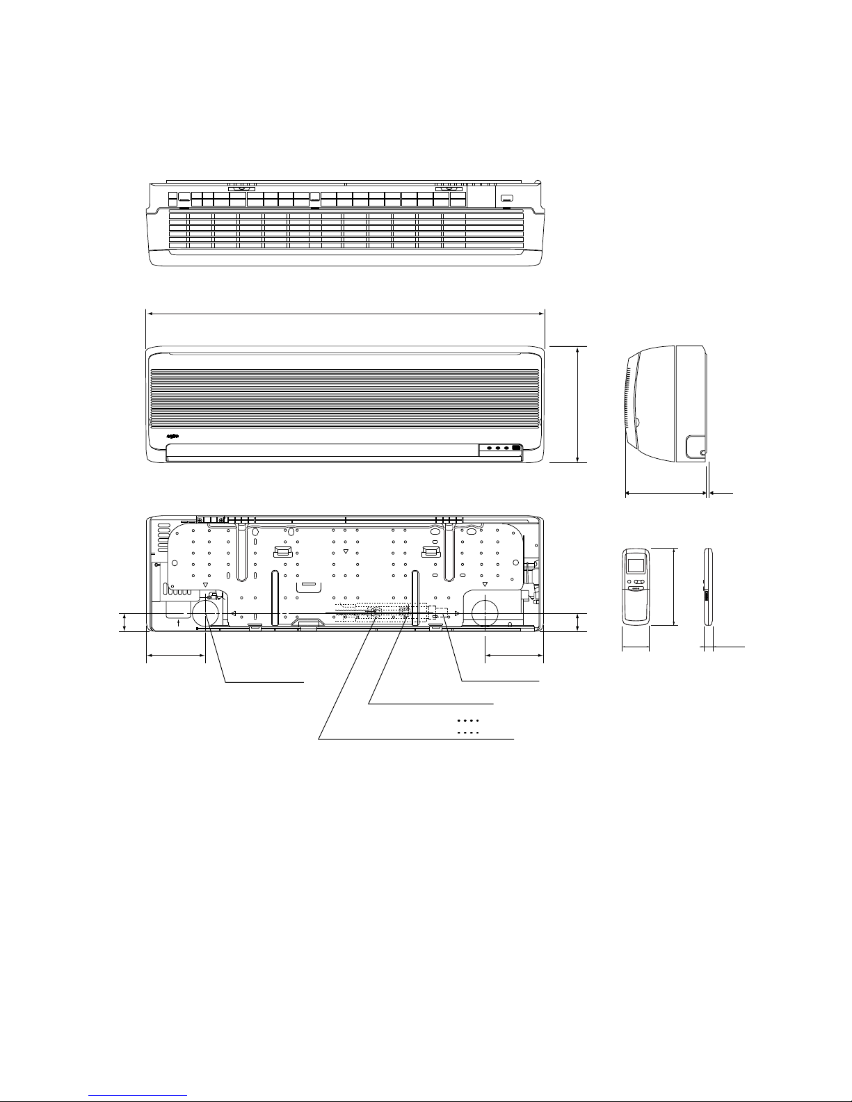
3. DIMENSIONAL DATA
Indoor Unit FCR518HL FCR522HL
Remote control unit
86
74 74
Center of tubing hole
ø75 (4 places)
Wide tube ø12.7 (1/2")
Narrow tube ø6.35 (1/4")
Drain hose ø26
74 74
61 18.5
900
86
41
41
190
680
Wide tube ø15.88 (5/8")
FCR518
FCR522
172.5
Dimensions : mm
16
17
Indoor Unit AWR518HL
28545
995
45
147.5 147.5
206 (3)
Remote control unit
Center of tubing
hole (2 places)
Narrow tube ø6.35 (1/4")
Drain hose ø18
Wide tube ø12.7 (1/2") AWR518
Wide tube ø15.88 (5/8") AWR522
61
18.5
172.5
Unit : mm
AWR522HL

18
Outdoor Unit AER518SH3
Air discharge
Air intake
538 146
307
337
4 – ø12 holes
830
19
630
305
61
95
Wide tube service valve
ø12.7 (1/2")
Narrow tube service valve
ø6.35 (1/4")
Unit : mm

19
Outdoor Unit : AER522SH3
Wide tube service valve ø15.88 (5/8")
Narrow tube service valve ø6.35 (1/4")
86
88
155
57
7386
229
285
835
620130 100
20
20
325
850
250250
560
6 – ø3.1 holes
Air intake
Air discharge
Unit : mm
 Loading...