

Euro Kitchen Appliances 198 series User Manual

USE, CARE, AND INSTALLATION GUIDE
Read all Instructions before Installing and oper
ating this appliance
IMPORTANT SAFETY NOTICE
WARNING
The installation in this manual is intended for qualified installers, service technicians or persons
f. Injury could
All electrical wiring must be properly installed, insulated and grounded. Overly accumulated
uct work should be replaced if necessary to
avoid the possibility of a grease fire. Check all joints on duct work to insure proper connection
liance. Save these instructions for
Always leave safety grills and filters in place. Without these components, operating blowers
NEVER leave cooking unattended. When frying, oil in the pan can easily overheat and catch
in the blower and filters may cause increased inflammability.
Filters must be cleaned periodically and free from accumulation of cooking residue (see
instructions inside). Old and worn filters must be replaced immediately. Do not operate
blowers when filters are removed. Never disassemble parts to clean without proper instructions.
Call our service
Kitchen, Inc. declines all responsibility in the event of failure to observe the
ines all responsibility for injury due to negligence and the
MODEL: EURO KITCHEN 198 Series Island -Mounted
Installation
with similar qualified background. DO NOT attempt to install this appliance yoursel
result from installing the unit due to lack of appropriate electrical and technical background.
grease in old duct work should be cleaned out or d
and all joints should be properly taped.
Operations
Read all instructions in this manual before operating the app
future reference.
could catch on to hair, fingers and loose clothing.
NEVER dispose cigarette ashes, ignitable substances, or
fire. The risk of self combustion is higher when the oil has been used several times.
any foreign objects into blowers.
Cleaning
The saturation of greasy residue
Keep unit clean and free of grease and residue build-up at all times to prevent possible fires.
cleaning
Disassembly is recommended to be performed by qualified personnel only.
center for removal instructions.
Euro
instructions given here for installation, maintenance and suitable use of the product.
Euro
warranty of the unit automatically expires due to improper maintenance.
-
-Kitchen, Inc. further decl

CONTENTS
INSTALLATION
Mount heights & clearance
Ducting
Mounting the hood
Duct cover
MAINTENANCE
Cleaning
Lights replacement
WARRANTY
Coverage & exceptions
------------------------------------------------------------
----------------------------------------------------------- 5
----------------------------------------------
-------------------------------------------------------- 4
--------------------------------------------- 5
---------------------------------------
------------------------------------ 1
1,2
3,4
6
INSTALLATION
1
reducer. Reduce duct size as far away from opening
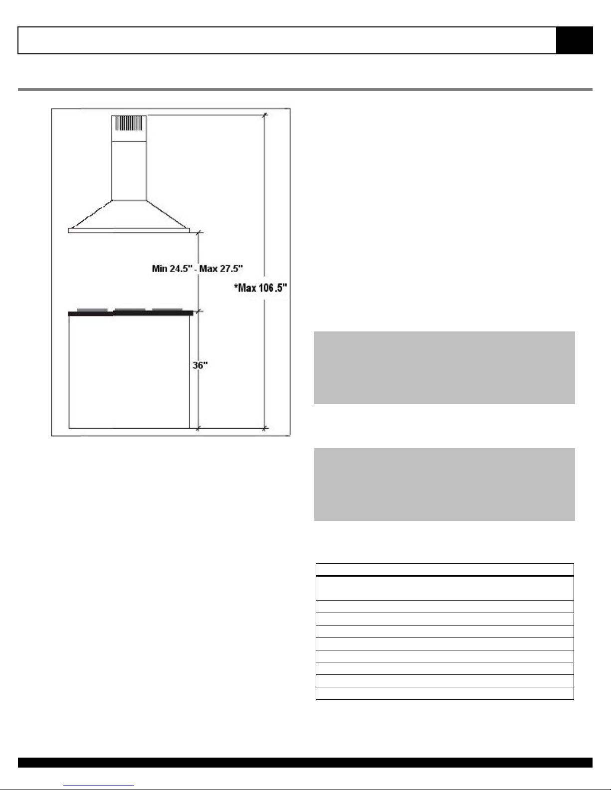
MOUNT HEIGHTS & CLEARANCE
Minimum mount height between range top to hood
bottom should be no less than 24.5".
Maximum mount height should be no higher than
27.5"
DUCTING
A minimum of 6" round or 3-1/4 x 10" rectangular
duct must be used to maintain maximum airflow
effici
ency.
It is important
mounting height. Hoods mounted too low could
result in heat damage and fire hazard; while hoods
mounted too high will be hard to reach and will loose
its performance and efficiency.
If available, also refer range manufac
clearance requirements and recommended hood
mounting height above range.
* Maximum ceiling clearance 106.5" at 27.5" hood
mounting height (different model may various).
**Higher ceiling require chimney extension available
at http://www.carlsonsappliance.com
Minimum Duct Size:
Round- 6" minimum
Rectangular- 3-1/4 x 10" minimum (requires a 6" to 3
1/4x10" adaptor not supplied
to install the hood at the proper
turer's height
-
-
Flexible ducts are provided for convenience, always
use rigid type metal ducts if available to maximizing
airflow.
Also use calculation (on right) to compute total
available duct run when using elbows, transitions
and caps.
ALWAYS, when possible, reduce the number or
transitions and turns. If long duct run is required,
increase duct size from 6" to 7 or 8". If a reducer is
used, install a long reducer instead of a pancake
as possible.
If turns or
Install as far away from opening and as far apart,
between 2, as possible.
transitions are required:
Duct Run Calculation:
Maximum run
6" or 3-1/4 x 10" duct
Deduct:
each 90 Elbow used
each 45 elbow used
each 6" to 3/14 x 10"
transition used
each 3/14 x 10" to 6"
transition used
Side Wall Cap w/ damper
Roof Cap
e.g.- 1 roof cap, 2x90 elbows, 1 45 elbow used:
=30' + 30' + 9' =69' used, 31' available for straight duct
runs.
100 FT
15 FT
9 FT
1 FT
5 FT
30 FT
30 FT
 Loading...