

Euroheaters EUROB1016 Operation Manual

1
www.euroheaters.com
EUROB1016 Intelligent Pressure Gauge
Operation Manual
2
www.euroheaters.com
Welcome for choosing and using our EUROB1016 intelligent pressure gauge. This manual enunciates
the functions and methods for use of intelligent pressure gauge in detail. Before using this intelligent
pressure gauge, please refer to this manual for your correct use.
Functions and Purpose of Use
Researched and manufactured by our company, EUROB1016 intelligent pressure gauge is a control
instrument, first of it’s kind produced in Europe. Not only does it assimilate the strongpoint of the similar
foreign products, but also it boasts its own characteristics, especially applicable for measuring and
controlling temperature and pressure at an identical point for high-temperature melting articles. This
instrument features fine ap pearance and complete functions with excellent anti-jamming performance,
which ensures reliable operation of the system.
This instrument adopts two-level four-bit led, respe ctively displaying actual pressure value and setting
value. Annunciate or be possessed of pressure upper limit or lower limit, which can be output via relay
contact, voltage pulse, bi-directional silicon-controlled trigger, and two-circuit constant current (or constant
pressure). Programs can be debugged fully automatically through panel operation and what you should do
for system calibration is just to push down buttons lightly. This instrument employs three kinds of antijamming methods to ensure reliable functioning of the instrument: firstly, separate input from
microprocessor via ph otoelectric isolation circuit; secondly, adopt anti-jamming methods by applying of
software to ensure steady operation of software; and lastly, apply hardware program to monitor the system
and to enable automatic recovery of system program to normal operation after being jammed. It has been
proved through practice that high reliability can be ensured of system software by using the above
anti-jamming methods. Sy stem can thus function steadily and reliably.
This instrument is widely used for measuring and controlling of pressure of high-temperature melting
articles in industries such as petroleum, chemical fibers and plastics.
Main Technical Specifications and Performance
01).Digital display: two-level four-bit display;
01).Internal resolution: 32000;
02).External resolution: pressure, 0.01Mpa, 0.02Mpa,
0.05Mpa panel switch (power-off protection
installation
≥40
years);
04).Nonlinearity: 0.5%±1 word, 0.2%±1 word, 0.1%±1
word, 0.05%±1 word;
05).Two-circuit alarm setup: pressure upper limit:
0~99.99Mpa, lower limit:
0~99.99Mpa;
06).Rated value of relay: 250VAC, 5A;
07).Operation environment:-10~+50℃, 80%RH;
08).Power supply: 85~265VAC;
09).Continuous working time: long period;
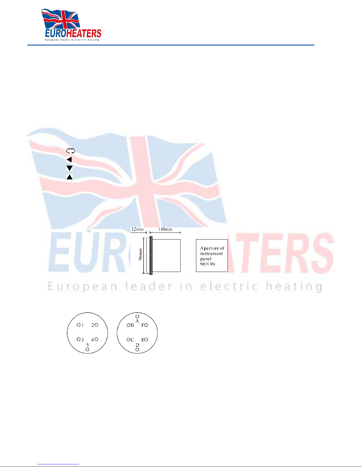
10).Aperture size: 90×90×110(mm).
3
www.euroheaters.com
Outside and structural dimensions
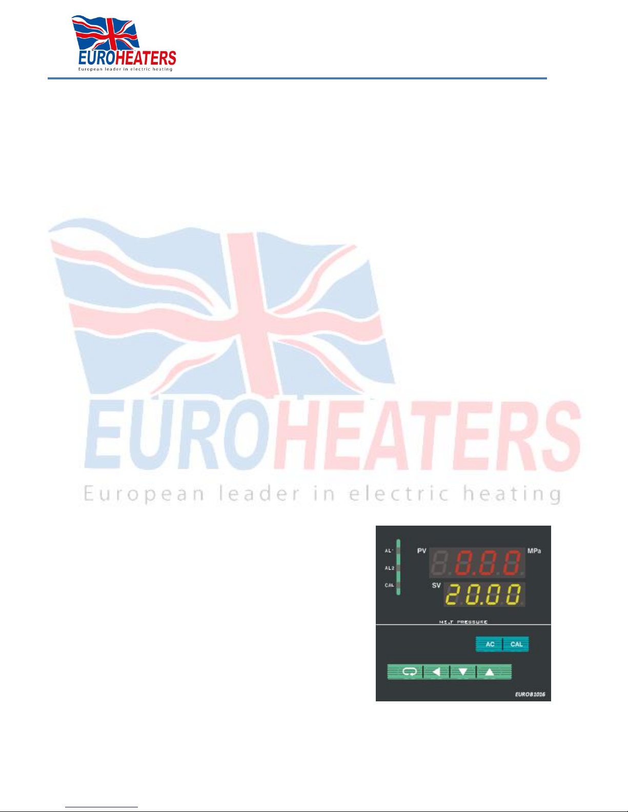
Display Window
Upper display window: displays measured value of actual pressure as well as parameter codes when
modifying internal parameters.
Lower display window: displays measured value of actual pressure as well as parameter amended
when modifying internal parameters.
Function Keyboard
AC: Reset zero key: (if pressed with switch key simultaneously, reset; press AC key for more than
5 seconds and zero, i.e. zero in calibration, can be recovered;
Cal: Calibration key: if pressed with switch key simultaneously, calibration can be done automatically.
Conversion key
Shift key
Down key
Up key
Signal Lamp
AL1: Alarm signal lamp for pressure upper limit
AL2: Alarm signal lamp for pressure lower limit
Cal: Signal lamp for calibration state (if calibration done automatically, the lamp flashes)
Diagram of installation dimensions
Methods of Use
● Connection of instrument with pressure transducer:
Connection for transducer plugs is as follows: (numerically marked plugs are of Type I alphabetically
marked plugs are of Type II. Please give clear indication if order)
1. A……………S+Positive signal(blue)
2. B……………E+Negative bridge pressure(red)
3. C……………S-Negative signal(yellow)
4. D.E…………E-Negative bridge pressure(white)
5. F……………C Calibration (green)
Connect all leads with the connection terminal at the back of temperature and pressure gauge (the re
are signs on connection terminal) and earth the shielded wire.
 Loading...