

Euroheat thermodual tda 30, thermodual tda 40 Installation & Servicing Instructions Manual

Installation Servicing Instructions
Thermodual TDA
30/40
www.euroheat.co.uk
Part Number:
Serial Number:
TDA Thermodual Installation Manual
2 IN1233 Oct 2014 Edition 5 Installation Servicing Instructions
EASY AND SAFE OPERATION This operating manual contains important instructions on the
• SHT TDA Thermodual 30
• SHT TDA Thermodual 40
READING THE INSTALLATION MANUAL This installation manual must be read and applied by everyone
who operates or works on the heating system SHT TDA
Thermodual
TECHNICAL CHANGES We continuously develop and improve our boilers. The
information in this edition was correct at the time of going to
press. All details in these instructions on standards, regulations
and worksheets should be checked before use and should be
compared with the regulations applying locally at the site
where the boiler is installed. We reserve the right to make
changes which may then deviate from the technical details
and illustrations in this operating manual.
1.1 Structure of
the Installation
Manual
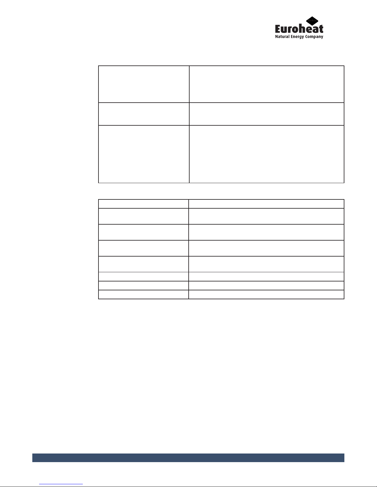
NOTES ON THIS MANUAL This explains how to use this operating manual.
SAFETY NOTES This explains everything on the subject of safety that you
should consider when using the heating system.
PLANNING AND INSTALLATION This explains how to properly plan for and install the heating
system.
COMMISSIONING THE SYSTEM This explains how the heating system is to be put into initial
service.
CLEANING AND MAINTAINING THE
HEATING SYSTEM
This explains how to clean the heating system and who is
responsible for its maintenance.
TROUBLESHOOTING This explains how to rectify faults in the heating system.
WARRANTY This explains the terms and conditions of the warranty.
APPENDIX This explains the EC Declaration of Conformity.
1. Introduction

IN1233 Edition 2 Installation Servicing Instructions 3
TDA Thermodual Installation Manual
2. Safety instructions
2.1 Intended
use
BASIC PRINCIPLES FOR THE CONSTRUCTION OF THE SYSTEM
BASIC PRINCIPLES
The heating system was built using state of the art technology
and conforms to recognised safety regulations. Nevertheless, its
use still poses the risks of injury or death of the user or a third
party, and of adverse effects upon the heating system itself or
upon other material goods.
Have your specialist heating company provide you with a detailed
explanation of the operation of the heating system.
USING THE HEATING SYSTEM
Only use the heating system if in perfect condition. Use it properly,
as intended, and be aware of safety concerns and the dangers
involved under observance of the operating manual. Have any
faults which could impair safety fixed immediately.
BASIC PRINCIPLES REGARDING THE CONTENT OF THE OPERATING
MANUAL
SCOPE
The content of this operating manual is intended exclusively for
the planning, installation and operation of the heating system
TDA Thermodual. Any further implementation of applicable
standards, for example with regard to the installation of the
heating system (pipework, etc.) is not part of this operating
manual. SHT Austria does not assume any liability for this.
APPLICATION OF THE
HEATING SYSTEM
The heating system TDA Thermodual is designed for the use
of wood pellets conforming to EN Plus standard and split logs
(w<30 %); materials not suitable for combustion are: wood dust,
wood chips, solid- liquid- or gaseous fossil fuels, etc. In addition
no PVC-containing waste products, cardboard containers, paper,
coated wood, etc. must be burnt; the wood must be free from
foreign bodies (nails, screws,etc.). See Section 3.4 for more
details on fuels. Fuels prepared from painted, varnished or coated
wood should not be used. Any other application is considered
improper use. The manufacturer will accept no liability for any
damage resulting from improper use. The operating company/
owner bears sole responsibility in such cases. Proper use includes
adherence to the installation, operation and maintenance
requirements specified by the manufacturer.
Modification of the specified operating values will affect the
heating system’s control program and could lead to malfunctions.
Only trained maintenance and operating personnel may
undertake modifications to the operating values.
UK SMOKE CONTROL AREAS
The TDA Thermodual models have been recommended for
exemption under Section 21 of the Clean Air Act 1993 for use in
smoke control areas when burning wood logs or wood pellets
which are selected in accordance with the recommendations on
fuel in this manual.

TDA Thermodual Installation Manual
4 IN1233 Oct 2014 Edition 5 Installation Servicing Instructions
Contact with the hot surfaces of the boiler can lead to burns. Wait until the boiler has cooled
down before touching uninsulated components.
Danger of asphyxiation and explosion from carbon monoxide. When the boiler is in operation,
carbon monoxide escaping from opened cleaning or inspection hatches can pose a danger of
asphyxiation or explosions. Do not leave these open any longer than necessary.
Opening doors and lids to hot combustion residues can pose the danger of fires. Keep the
openings closed during operation, and when performing cleaning work, allow the combustion
residue to cool down before you place them in a fireproof container.
The boiler weighs over 750kg. If the boiler is dropped during transport, persons can be
seriously injured and the boiler can be damaged. Make sure that you use appropriate lifting gear
when transporting, moving and installing the boiler.
When working on the pellet grate, cleaning turbulators, and pellet delivery systems, hands
or arms could be injured. Turn off the main power switch when working on these components.
2.2 Residual
Risk
IN1233 Edition 2 Installation Servicing Instructions 5
TDA Thermodual Installation Manual
3. Scope of Delivery
3.1 Scope of
Delivery
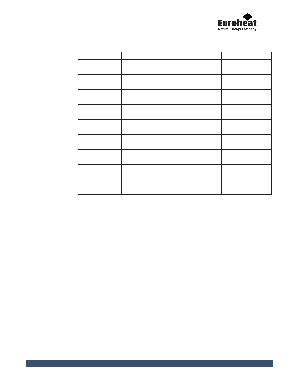
Article Number Description Quantity Pre-Installed
8B2420
Boiler Body TDA 1 N
8C2410
Induced draught fan with flange 1 Y
9M3242
Data plate 1 N
2I2416
Secondary air flap insulated gasket 1 Y
2H2209
Seal for draught fan 10mm 1 Y
9W0001
SHT Logo 1 Y
8C2412
Primary air flap, complete 1 Y
8C2414
Primary air flap, complete 1 Y
1K2422
Casing complete, including TC3 wiring loom 1 Y
8A4230
Thermocontrol panel TC3 1 Y
8A4240
Thermocontrol IO circuit board TC3 1 Y
B21025
EW1 extension module 1 Y
4A2216
Immersion sensor 3 N
4A4210
External sensor AF200 1 N
4A4212
Flow sensor VF202 2 N
2X4305
Insulated glove 2 N
2X2516
Round brush 48 x 100 x 1200mm 1 N
A21002
Cleaning set VN 22-55 1 N
Please check your appliance carefully after unpacking for signs of damage and to ensure all parts
have been delivered. Record any visible defects on the delivery note and inform the supplier
immediately. Please take pictures of any damage for future reference.
3.2 Unpacking
and Inspection

TDA Thermodual Installation Manual
6 IN1233 Oct 2014 Edition 5 Installation Servicing Instructions
TDA rear view (with casing) TDA right side view (with casing)
TDA front view (with casing) TDA left side view (with casing)
4. Technical Data
IN1233 Edition 2 Installation Servicing Instructions 7
TDA Thermodual Installation Manual
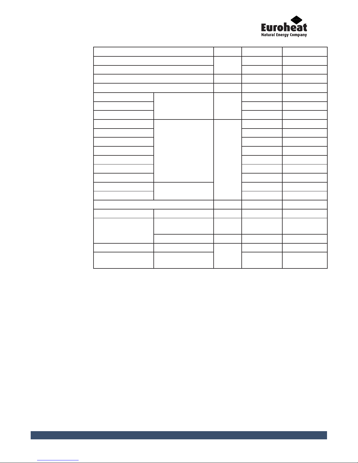
TDA 30 TDA 40
Nominal rating*
kW
28 38
Power range 8.4 - 28 11.4 - 38
Boiler water content Litres Ltr approx. 150 approx. 150
Fuel capacity Ltr approx. 175 approx. 175
Width
Boiler dimensions
without casing
mm
761 761
Height 1500 1500
Depth 1207 1207
T
Boiler dimensions
with casing
mm
1184 1184
T1 1220 1220
B/B1 865/852 865/852
H 1594 1594
A 1322 1322
C 830 830
D 563 563
E
Filling door opening
400 400
F 337 337
Boiler weight kg approx. 780 approx. 780
Ø Flue pipe mm 150 150
Draught
requirement**
Pa 15 15
Heating surface m2 2.1 2.1
G Supply and return
Inch
5/4 5/4
G
Safety
supply and return
3/4 3/4
*The type-tested capacity range is to be inferred from the original test certificates and may
differ slightly from the values specified.
**Pressure conversion from Pa to bar
105 Pa [N/m²] = 1 bar
Conversion example:
105 Pa = 1 bar
100,000 Pa = 1 bar
20 Pa = 0.0002 bar = 0.2 mbar
TDA Thermodual Installation Manual
8 IN1233 Oct 2014 Edition 5 Installation Servicing Instructions
Control unit
Door contact switch
Log Loading door
Log loading space
Secondary air flap
Secondary-combustion
chamber
Ash door
Ash pans
Primary air flap
Pellet insertion
channel
Ignition element
Control panel
Control unit/circuit
board:
All data is saved on the circuit board. All operational sequences are coordinated
via the control unit/circuit board.
Control panel: The entire system is operated via the control panel.
Door contact switch: The door contact switch indicates whether the filling door and ash door are
closed.
Log loading door The filling door must be opened to insert firewood.
Log loading space Firewood is inserted into the filling space.
Secondary-combustion
chamber:
Unburnt gases are burnt in the secondary combustion chamber.
Ignition element: The ignition element ensures automatic ignition of the pellets/firewood.
Primary air flap: The primary air required for combustion flows through the primary air flap.
Secondary air flap: The secondary air required for combustion flows through the secondary air flap.
Ash door: The ash door must be opened to access the ash chamber.
Ash pan: All unburnt material is collected in the ash pans.
Pellet insertion
channel:
Transports pellets into the pellet combustion chamber.
5. Overview
5.1 Main Components

IN1233 Edition 2 Installation Servicing Instructions 9
TDA Thermodual Installation Manual
5.2 External
Casings
11
2
14
4
10
3
13
9
1
12
8
7
6
5
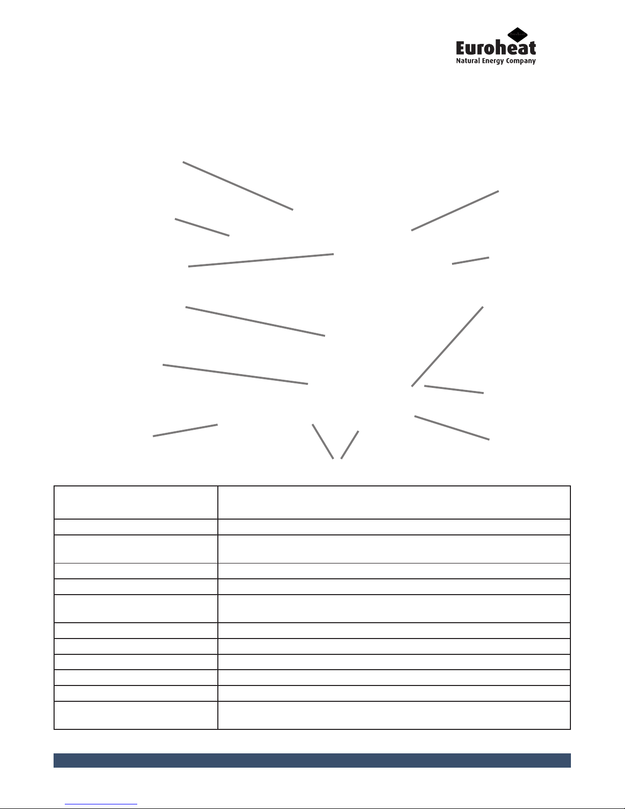
Description
1 Rear panel
2 Base plate and insulation pad
3 Left hand side panel
4 Right hand side panel
5 Control panel bracket
6 Control panel
7 Side cover
8 Filling plate
9 Control unit cover
10 Design element and protective cover
11 Front lid and insulation pad
12 Rear lid and insulation pad
13 Rear cover/flame sensor cover
14 Ash tray

TDA Thermodual Installation Manual
10 IN1233 Oct 2014 Edition 5 Installation Servicing Instructions
A
C
C
B
B
Legend TDA 30/40
A 2875
B 2260
C 2500
Legend TDA 30/40
A 3270
B 2750
C 2357
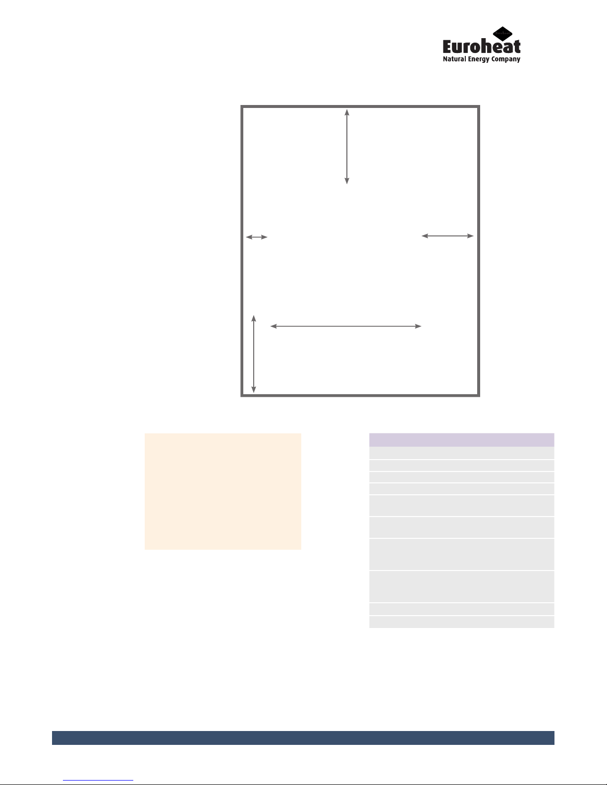
6.1 Minimum
Boiler Room
Sizing with
Single
2500 Litre
Accumulator
6. Boiler Room Sizing
6.2 Minimum
Boiler Room
Sizing with
Twin 1250 Litre
Accumulators
IN1233 Edition 2 Installation Servicing Instructions 11
TDA Thermodual Installation Manual
Measurement Description TDA 30/40
A Wall to front 650
B Wall to right 300
C Wall to rear 500
D Wall to left 100
E
Width with manual fill
pellet hopper
1420
E
Width with intermediate
pellet hopper
1325
Minimum room width
with manual fill pellet
hopper
1820
Minimum room width
with intermediate pellet
hopper
1725
Minimum room depth 2357
Minimum room height 2100
Please note the above
dimensions do not include the
accumulator or expansion vessel.
If siting the accumulator in the
boiler room then the necessary
dimensions will need to be
increased respectively
(including room height).
6.3 Minimum
Clearances Manual Fill &
Intermediate
Pellet Hopper
C
B
E
A
D
TDA Thermodual Installation Manual
12 IN1233 Oct 2014 Edition 5 Installation Servicing Instructions
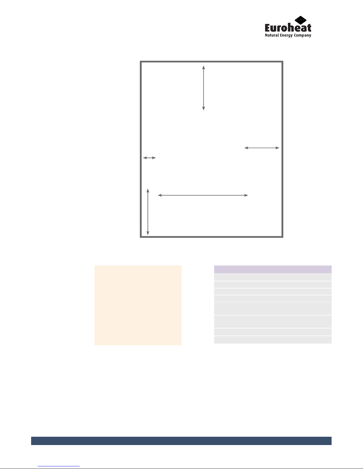
Measurement Description TDA 30/40
A Wall to front 650
B Wall to right 650
C Wall to rear 500
D Wall to left 100
E
Width with Vario auger
system
1127
Minimum room width
with Vario auger system
2077
Minimum room depth 2357
Minimum room height 2100
Please note the above
dimensions do not include
the accumulator or
expansion vessel. If siting
the accumulator in the boiler
room then the necessary
dimensions will need to be
increased respectively
(including room height).
6.4 Minimum
Clearances Vario Flexible
Auger
C
B
E
A
D

IN1233 Edition 2 Installation Servicing Instructions 13
TDA Thermodual Installation Manual
7. Boiler Assembly
Approved Document B, of the Building Regulations states that boiler houses are classed as “places
of special fire hazard”.
Requirements
The requirements for a designated compartment is that the responsible person must carry
out a risk assessment for the location and take into account the requirements of the Building
Regulations Approved Document B1 and B2 (For larger dwellings over 200 m2 per storey).
As a “Places of Special fire Hazard” there must be a separate fire compartment constructed.
This means that if an existing room is altered, such as a utility room or garage, it must be
fireproofed to make it a special compartment as well as in the case of a new construction.
This compartment should not form a part of one of the exits from the property that will
have to be used as a fire exit. There can be a door between the boiler house and the rest of the
property and there can be a door that from the boiler house to the outside but this cannot be
classed as one of the property exits.
As a “Places of Special Fire Hazard” it has to be treated as a separate compartment and the
materials used for the lining of the walls and ceilings for fire protection must meet the National
Class1 or European class C-s3,d2.
Any wall or floor between a garage and a house must have 30 minutes fire resistance with a
self closing door and must be classed as smoke sealed along its jambs and head.
Any services that pass through the wall between the boiler house and the dwelling should have
adequate fire stopping as ADB1 section 7, paragraphs 7.6-7.9 i.e. if the pipe is none combustible
and has an internal diameter less than 160 mm. • If the boiler house, plant room or fuel store is in
the basement of a property then this must have its own separate natural smoke and heat outlet.
7.1 Boiler
Room
Requirements
The boiler should only be installed in a dry room. The boiler has a minimum ventilation requirement
of 15,000mm2.in order to provide sufficient air for combustion. The ventilation should be located
at low level (within 1 metre of the floor height) if possible.
In installations where the ambient boiler room temperature is likely to exceed 30 degrees C (high
summertime use and or/highly insulated boiler room) additional high level ventilation should
be installed to dissipate excess heat.
7.2 Boiler Room
Ventilation

TDA Thermodual Installation Manual
14 IN1233 Oct 2014 Edition 5 Installation Servicing Instructions
7.3 Unhinge
Doors
Before lifting the boiler off the pallet, we recommend unhinging both the filling and the ash
door. Please put them down carefully to avoid any damage.
Do not unscrew the hinges on the boiler side panels as the doors may become misaligned and
therefore the door tightness and correct functioning of the door contact switches cannot be
guaranteed.
There are two possible ways to lift the boiler off the pallet. At least two persons should always
lift the boiler off the pallet.
Remove the top lid (front and rear) and top insulation slabs from the boiler. Attach a suitable
lifting hook to the two crane eyelets located on either side of the boiler. The boiler can then be
lifted using suitable lifting equipment (forklift, lifting frame).
Remove the base plate and insulation slab from underneath the boiler. A forklift can then be
used underneath the boiler to lift it from the pallet.
CAUTION. The boiler weighs over 750kg. If the boiler is dropped during transport, people can be
seriously injured and the boiler can be damaged.
Make sure that you use appropriate lifting gear when installing the boiler.
7.4 Lifting the
Boiler

IN1233 Edition 2 Installation Servicing Instructions 15
TDA Thermodual Installation Manual
The boiler should be installed on a non-combustible surface of a suitable construction. Adjust the
four legs on the base of the boiler so that it stands evenly or slightly raised to the rear.
7.5 Siting the
Boiler
Adjustable Legs
Place the ash tray in front of the assembled boiler.
7.6 Fitting the
Ash Tray
 Loading...