

Euroheat Harmony 44 Installation & Servicing Instructions Manual
PART NUMBER
SERIAL NUMBER
Installation &
Servicing Instructions
Harmony 44
Conventional Flue Gas Stoves
IN1113 Edition E June 2009

© EUROHEAT DISTRIBUTORS (H.B.S) LTD. June 2009
E & OE Instructions Part Number IN1113 Ed. E
1
Manufacturers Identification Plate
The identification plate is located under the gas valve.
To access the plate swing outwards.
The Euroheat Appliance Serial Number
The serial number can be found at 5 locations:
1: On the front page of this manual.
2: On the front page of the operating instructions.
3: On the identification plate located under the gas valve.
4: On the registration form.
5: On the registration certificate returned to the user after successful registration.
Contents
Safety Precautions 2
Technical Data for H44 3
Accessories Supplied with Stove 4
Flue and Chimney Requirements 6
Ventilation 6
Example of Stove Fitted into an Existing Chimney 7
Installation of the Gas Supply 8
Appliance Location 8
Installation of the Stove to the Flue System 9
Changing Flue Outlet Direction 10
Hearth and Fireplace Requirements 11
Minimum Installation Clearances 11
Installation of the Gas Log Effect 12
Placement of the Ember Glow Fibres 13
Gas Connection 16
Low Pressure Adjusting Screw 18
Gas Pressure Test Nipple Locations 18
Fitting the Remote Control 19
Commissioning 20
Information for Users Which must be Advised by the Installer Verbally or in Writing 21
Spare Parts for Servicing H44 Gas Stoves 21
Servicing Instructions 22
Burner Removal and Replacement 23
Thermocouple Replacement 25
Changing Gas Operating Type 28
Primary Air Collar Adjustment 28
Door Handle Adjustment 29
Lower Door Opening and Level Adjustment 29

© EUROHEAT DISTRIBUTORS (H.B.S) LTD. June 2009
E & OE Instructions Part Number IN1113 Ed. E
2
Safety Precautions
a) The stove should be visually inspected and if damaged should not be installed.
b) It is a requirement of the Gas Safety (Installation and Use) Regulations that these instructions,
together with the Appliance User Instructions, be left intact with the user.
c) In your own interest, and those of safety, and in accordance with the Gas Safety (Installation
and Use) Regulations, Euroheat stoves must be installed by a suitably qualified Gas Safe
technician using the appropriate fittings for the gas type being used, and the stove must not
be modified in anyway. The gas technician will be responsible for the installation conforming
to all current regulations and standards, during the life of this publication these standards may
be superceded and it is the installer’s responsibility to ensure the installation conforms to
whatever standards are current at the time of installation. Failure to install the appliance
correctly could lead to prosecution.
BS 715 : 1993 Metal Flue Systems
BS 1251 : 1987 Fireplace Components
BS 1289 : PT 1 1986 Flue Block Systems
BS 5440 : PT 1 2000 Flues
BS 5440 : PT 2 2000 Ventilation
BS 5871 : PT 1 2005 Installation of Gas Fires
BS 5482 : PT 1 1994 LPG Installations
BS 6891 : 1998 Pipe Work Installation
d) It is important to ensure that the flue system onto which the appliance is to be installed is
working properly. Products of combustion which enter a room could be a serious health risk. It
is therefore important, in the interests of safety, that these instructions are strictly followed,
together with the legal Statutes and Codes of Practice, current at the time of installation.
e) It is important that the stove is installed so that the clearances specified in these instructions are
complied with.
f) The stove must NOT be run with its door open.
g) It is also important that the occupiers of the property have their attention drawn to the high
temperatures which are normally present on the external surfaces of the stove during operation.
h) Fireguards, in accordance with current British Standards, should be fitted when the appliance is
in the presence of young children, the elderly or infirm.
i) Do not use the stove if any of the ceramic log or coal effect components are damaged or broken
during transportation.
j) Ensure that all transport packaging is removed from inside and outside of the stove.
k) The plastic bags used to protect components of this appliance are a potential hazard to young
children, and should be disposed of immediately.
l) The stove must be serviced annually by a suitably qualified Gas Safe technician.

© EUROHEAT DISTRIBUTORS (H.B.S) LTD. June 2009
E & OE Instructions Part Number IN1113 Ed. E
3
Harmony 44 Gas Conventional Flue
Model Number H44
Heat Output Maximum
Nat Gas 8.690 kW (29,650 BTU)
L.P.G. 8.05 kW (27,466 BTU)
Gas Input Maximum
Nat. Gas 10.23 kW (35,826 BTU)
L.P.G. 9.55 kW (32,584 BTU)
Heat Control Manual Mertik Maxitrol GV34 Gas Valve
Fuel Types Natural Gas or L. P. G.
(Specify at time of order)
Efficiency Natural Gas 85%
Efficiency L.P.G 84.3%
Ignition Type Piezo
Pilot Flame Yes
Flame Failure Yes
Flue Spillage Sensor Thermocouple Interrupter (TTB)
Fuel Effect Type Wood
Fuel Outlet Options Top or rear
Flue Size 4” (100mm) Internal Diameter
Free Air Requirement
Nat. Gas 1776 sq mm
L.P.G. 1402 sq mm
Gas Fitting Size 1/2” BSP or 3/8” BSP
Colour Options Cast Black, Satin Black Enamel, Bottle Green Enamel
Decorative Plinth Optional extra
Cast Black 88802001
Satin Black Enamel 88802002
Green Enamel 88802006
Remote control Optional extra MS9252
Technical Data for H44
Gas
Type
System
Pressure
Main
Burner
Nozzle
Nominal Output
(Maximum operation)
Minimum Output
(low operation)
Pilot
Nozzle
Size
Hourly
Input
Burner
Operating
Pressure
Hourly
Input
Burner
Operating
Pressure
G20
Na tu ra l
Gas
20mbar
1 jet
4 x 1.4
1.08
m³/h
10.6mbar
0.77
m³/h
5.6mbar 51
G31
Propane 37mbar
1 jet
4 x 0.81 0.76kg 27.8mbar 0.6kg 15mbar 22
Seasonal Efficiency
The efficiency of this appliance has been measured as specified in BS EN 613:2001 and the result is 76.6%
Nat Gas and 77.83% LPG. The gross calorific value of the fuel has been used for this efficiency calculation, the
Net Efficiency being 85% Nat Gas and 84.3% LPG. The test data from which it has been calculated has been
certified by BELTEST. The efficiency value may be used in the Governments Standard Assessment Procedure
(SAP) for energy rating of dwellings.
© EUROHEAT DISTRIBUTORS (H.B.S) LTD. June 2009
E & OE Instructions Part Number IN1113 Ed. E
4
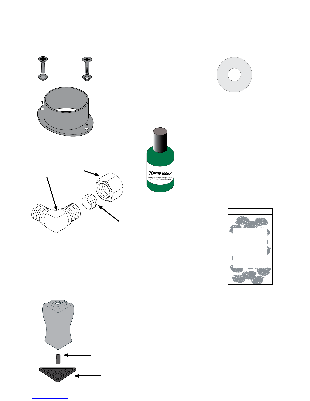
Flue Spigot (Collar) and Choke Plate
The flue spigot (collar) may be
found either screwed to the pallet
on which the stove is delivered or
within the body of the stove.
In the plastic bag within the stove
there will be 2 cup washers and 2
M5 x 20mm screws.
Elbow for Gas Fitting
Accessories Supplied with Stove
Supplied with the conventional flued gas stoves are a number of installation accessories and instruction
manuals.
Nut
Olive
Elbow
Foot Levelling Screws and Triangular Hearth Protectors
In the plastic bag within the stove there will be 4 foot
levelling grub screws and 4 plastic triangular hearth
protectors. The grub screws should be fitted to the feet
prior to installation to allow for levelling the stove on an
uneven hearth.
The plastic hearth protectors can be put under the feet to
protect the hearth when sliding the stove into position,
but should be removed unless required to help level the
stove.
Enamel Repair Touch Up
(Enamel Stoves Only)
In the plastic bag within the stove there
will be a bottle or tube of enamel touch
up which will match the enamel finish
on the stove. This can be used to repair
any minor chips on the enamel surface
of the stove.
Grub Screw
Plastic Hearth Protector
EMBERGLOW
Platinum
Bright
Embers
Emberglow
Small squares of platinum
embers which when teased
out give an ash effect with
the ceramic log or coal effect
(see page 13).
Choke Plate
This MUST be fitted to top
or rear flue applications,
see page 10.
© EUROHEAT DISTRIBUTORS (H.B.S) LTD. June 2009
E & OE Instructions Part Number IN1113 Ed. E
5
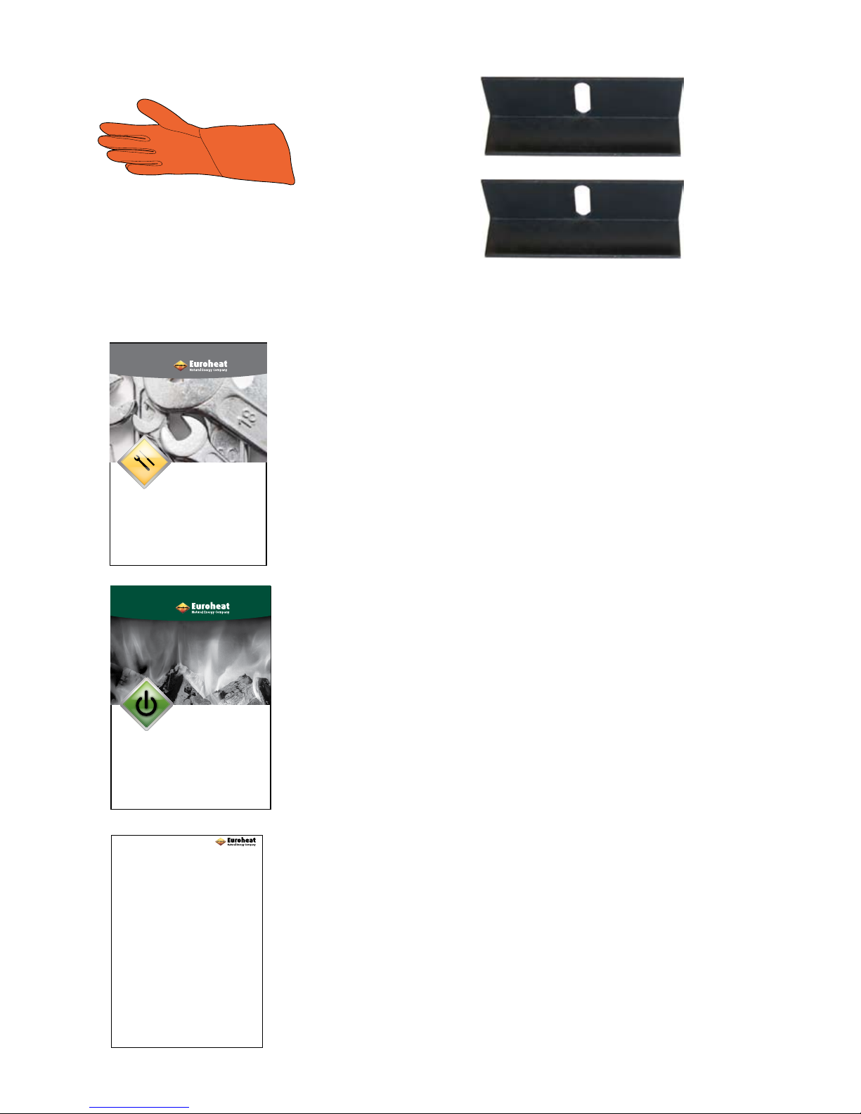
Glove
A heat proof glove is also supplied
with the stove. This is for use by the
installing and servicing engineer if
they have to open the main firebox
door when hot.
Burner Brackets
The two burner brackets are fitted inside the fire box on
the left and right inner walls. They are used to locate the
ceramic burner in place. They are supplied with 2 self tapping
screws.
If there are any of the above documents missing from your
stove upon delivery please contact Euroheat with the serial
number of the stove and we will immediately despatch a
replacement.
Installation Instructions
For the use of the suitably qualified engineer for the
installation and servicing of the stove.
It MUST be handed to the owner of the stove.
Operating Instructions
For the use of the person for the safe operation of the stove.
It MUST be handed to the owner of the stove.
PART NUMBER
SERIAL NUMBER
Installation &
Servicing Instructions
Harmony 44
Conventional Flue Gas Stoves
IN1113 Edition E June 2009
PART NUMBER
SERIAL NUMBER
Operating Instructions
Harmony
Stanford
Conventional Flue Gas Stoves
IN1123 Edition 02 June 2009
GAS STOVE REGISTRATION
Please complete the form on pages 3 and 4 and return it with a
copy of your sales receipt from your Euroheat approved supplier
to obtain your
THREE GOOD REASONS
Why you should have your stove commissioned.
It is vital for the longevity and efficient and safe operation of the stove to have the stove installed and
commissioned by a competent qualified heating engineer.
1. Installation
The stove should be installed by a competent qualified heating engineer, who will be conversant with the
Building Regulations and Codes of Practice current at the time of installation. Installation instructions are
supplied with the stove which contain instructions specific to the appliance.
Incorrect installation may lead to poor performance of the stove and ultimately damage to the appliance.
2. Operating
The operation of the stove should be demonstrated by a competent person, so you, as the operator, are
conversant with the operation of the controls. Instructions on the use of the controls can be found in the
operating instructions supplied with the stove.
Incorrect operation of the controls of the stove may lead to poor performance from the stove and ultimately
damage the appliance.
3. Maintenance
Routine maintenance as described in the operating instructions, supplied with the stove, should be
undertaken by a competent person.
Failure to perform the routine maintenance may adversely effect the performance of the stove and
ultimately damage the appliance.
Registration Form
To be completed by both the owner of the stove and the installing/
commissioning engineer.
It MUST be returned to Euroheat for the registration to be completed.

© EUROHEAT DISTRIBUTORS (H.B.S) LTD. June 2009
E & OE Instructions Part Number IN1113 Ed. E
6
Flue and Chimney Requirements
BS 5440 : PART 1
Before installation of the appliance, the chimney or flue system must be inspected and passed as suitable.
In particular, the following should be checked:
a) This appliance is suitable for installation onto the following flue types:
A suitable sized diameter flexible or fabricated steel flue system (See appliance data for
flue size), or a precast flue system (See Technical Bulletin TB118).
b) We would strongly recommend that a flue liner is also fitted if being installed into an existing
chimney built with an integral clay liner.
c) If being installed into an existing masonry flue which has NOT been built with an
integral clay liner, a flexible flue liner MUST always be used to line the entire chimney.
NOTE:
Any steel flue systems used should be manufactured in line with the requirements of BS 715, and
installed with due regard to the manufacturers recommendations.
d) The chimney should be thoroughly swept prior to installation of the flue liner. However,
if the flue is clean and unobstructed throughout its entire length, it need not be swept.
e) The chimney or flue must be free from any obstruction. Any flue damper or restrictor
must be removed or permanently fixed in the fully open position.
f) The minimum effective height of the chimney or flue must be 10ft (3 metres) measured
from the hearth to the termination of the flue (chimney pot). If the flue has any non
vertical sections the height should be increased in line with BS 5440 : Part 1.
For further information see the Euroheat Flue Guide IN1087.
g) An approved gas flue terminal MUST be fitted in accordance to the manufacturers
recommendations.
h) Where required a closure plate, of a suitable non-combustible material should be fitted. This
should have an infill panel so as to facilitate removal of any debris that may fall down
the chimney. Even after sweeping soot or debris may continue to fall down the chimney.
Ventilation
BS 5440 : PART 2
Before proceeding further, the following ventilation requirements must be satisfied.
a) If the stove is installed in a builder’s opening or fireplace recess that has an air supply entering from below
floor level, or within the opening or recess, this must be completely sealed off.
b) If there is another gas appliance fitted in the same room, or adjacent area, or extractor fan system, air
conditioning, etc., it will be necessary to refer to BS 6714 and BS 5440 : Part 2 to ascertain the additional
precautions necessary.
If any of the pre-installation checks reveal inadequacies, the installation should not proceed until they are
rectified.
Do not fit the appliance, seek expert advice.
© EUROHEAT DISTRIBUTORS (H.B.S) LTD. June 2009
E & OE Instructions Part Number IN1113 Ed. E
7
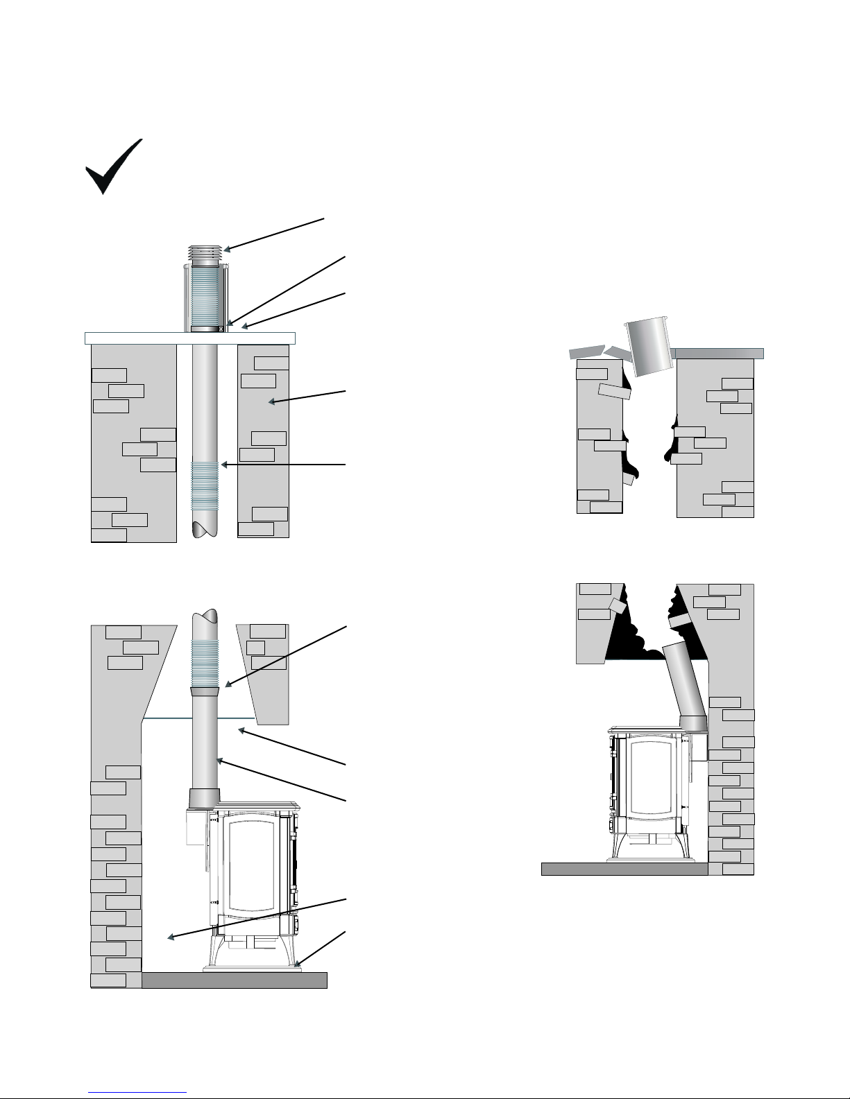
Suitably approved cowl
to prevent ingress of rain,
birds and/or to assist with
flue stabilization
Flue liner support collar
Weatherproof chimney
capping and pot
Sound chimney brick work
Stainless steel liner
Flexible to single wall
adapter
Register plate preventing the
escape of heat, positioned as low
as practicable to aid convection.
There must be an access door
to facilitate debris removal and
inspection.
Sufficient clearance behind
stove for maintenance
Level and stable supporting
hearth
Ridged section of flue pipe
Example of Stove Fitted into an Existing Chimney
For further information on flues ask you retail outlet for Technical Document IN1087 The Flue, or if the
installation is to be into a pre cast flue Technical Bulletin 118.
X
Height of flue less than 3 meters
Height of flue greater than 3 meters
The example above shows an
unacceptable installation into an
unsound and unlined flue. The height
is less than 3 meters and there is no
cowl.

© EUROHEAT DISTRIBUTORS (H.B.S) LTD. June 2009
E & OE Instructions Part Number IN1113 Ed. E
8
Installation of the Gas Supply
BS 6891
NOTE: Ensure that the gas supply is capable of delivering the required amount of gas, and is in
accordance with the relevant current standards.
It is generally preferred to conceal the gas supply by bringing it under the hearth, or through masonry to
the side of the fireplace. Any pipe work in 8mm tube connecting the stove to the main pipe work should be
kept as short as possible with as few fittings as possible to prevent restrictions.
a) Whenever a gas pipe passes through any masonry it must have a sleeve of non
combustible material sealed at both ends to prevent the gas supply from coming in
contact with masonry or lime based mortars.
b) The gas pipe should be adequately supported over longer lengths.
c) Soft copper tubing and soft soldered joints are suitable, providing the tube is not closer than
150mm to the stove casing, i.e., the temperature must not exceed 100°C.
d) A means of isolating the gas supply to the appliance must be provided, unless the
appliance is supplied with its own isolation valve, independent of any appliance control
(gas control valve). This may be a gas cock, ideally of the nursery type to prevent
children interfering with the gas supply.
e) Any gas tubing that has been passed through masonry, should be purged to expel
any foreign materials that may have entered the supply.
Care should be taken to ensure that pipe work brought through metal structures has been secured to prevent
chaffing, but allow for thermal expansion.
Appliance Location
a) In a fireplace recess the stove can be mounted on a 12mm thick decorative hearth or plinth, if
a constructional hearth of the correct dimensions is in place. In a free standing situation, as the
hearth temperature does not exceed 100ºC, a constructional hearth is not required. The stove
can be mounted on a 12mm thick non-combustible decorative hearth of the correct size i.e. a
cast iron plinth, provided that the floor can support the weight.
b) The stove is not suitable for installation into a rear combustible wall, any combustible
material must be removed from an area of 300mm around the installation of the appliance.
c) There must be a minimum of 300mm (see page11) from the top of the stove to the
underside of any combustible shelf. Note that for every 50mm increase on clearance, the
shelf may project by a further 50mm.
d) The appliance must not be installed in a room or space which contains a bath or shower, or if the
room is used as sleeping quarters.
e) Ensure that the stove fits neatly into its intended location.
f) Any manufactured surround used with this stove should comply with the appropriate British
Standard.
g) Do not place furniture or furnishing within 1 metre of the stove.
h) Do not obstruct the area directly beneath the stove as this may block the passage of air into
the appliance.
If any of these conditions are not fulfilled,
DO NOT FIT THE STOVE until the problem has been rectified.

© EUROHEAT DISTRIBUTORS (H.B.S) LTD. June 2009
E & OE Instructions Part Number IN1113 Ed. E
9
Installation of the Stove to the Flue System
Refer to page 6 to determine which flue systems are suitable for your stove size, having selected a suitable
flue system, please follow the applicable installation method.
Installation to a Flue Pipe System
IMPORTANT: The flue pipe system should be manufactured in line with BS 715, it should be either
a flexible flue liner or a rigid tubular steel construction, and it must be continuous from appliance
outlet spigot to terminal.
IF IT IS INTENDED TO FIT INTO AN EXISTING MASONRY BUILT CHIMNEY SYSTEM A SUITABLE DIAMETER
FLEXIBLE FLUE LINER MUST BE USED.
(See page 4 appliance data for flue size)
If fitting to a pre cast flue system refer to Technical Bulletin 118.
The stove is factory assembled for top flue connection. To choose a rear flue option follow the instructions
on page 10.
The flue system may now be connected to the stove, ensure that all joints are sealed with a suitable fire
resistant sealant we recommend Fraxfill (available from Euroheat Part No: MS9045).
Some so called “Heat Proof” mastiks will only stand a temperature of 300°C before they start breaking down.
In many cases they may give off an obnoxious smell at temperatures much lower than this and therefore
should not be used on this type of installation.
A physical retention method MUST be used at the flue spigot joint with the flue pipe, self tapping screws
being favoured.
Note:
If the flue is to be connected to the rear outlet, there should be no more than 150mm of horizontal
flue run before the flue rises vertically. Under certain circumstances it may be necessary to use a 45
degree bend directly from the top of the stove, this is acceptable as long as it does not compromise
the performance of the flue and the stove passes the necessary flue spillage test.
 Loading...