

Euroheat Harmony 35, Harmony 45 Installation & Servicing Instructions Manual
Installation &
Servicing Instructions
Harmony 35
Harmony 45
Balanced Flue Gas Stoves
IN1156 Edition E March 2012
PART NUMBER
SERIAL NUMBER
© EUROHEAT DISTRIBUTORS (H.B.S) LTD. March 2012 E & OE Instructions Part number IN1156 Ed. E
2
Contents
Technical Data with Mertik Maxitrol GV34 Gas Valve 4
Accessories Supplied with Stove 6
Appliance Location 8
Installation of the Gas Supply 9
Flue Spigot Fitting 10
Installation of the Flue System 13
Installation of the Gas Log Effect 14
Placement of the Ember Glow Fibres 15
Fitting of the Gas Log Effect 15
Gas Connection 19
Gas Pressure Test Nipple Locations 21
Fitting the Remote Control 22
Information for Users Which Must be Advised by the Installer Verbally or in Writing 23
Spare Parts for Servicing H35 and H45 Gas Stoves 24
Changing Gas Operating Type 25
Primary Air Collar Adjustment 25
Servicing Instructions 26
Burner Removal and Replacement 27
Thermocouple Replacement 29
Door Handle Adjustment 31
Lower Door Opening and Level Adjustment 31
When installing the stove this document should be used in
conjunction with the Euroheat Balanced Flue Technical Guide,
Document No: IN1105.
Balanced Flue Stove
Technical Guide
Document No: IN1105
Information from the Euroheat Technical Team
Euroheat and Nestor Martin have a policy of continual research and development and reserve the right to
modify its appliances without prior notice. We make every effort to ensure that the information provided in
this document is correct and accurate at the time of printing. Continued updates occur to adapt documents to
customer requirements and appliance changes. For the latest editions of all Euroheat documentation visit our
web site www.euroheat.co.uk.

© EUROHEAT DISTRIBUTORS (H.B.S) LTD. March 2012 E & OE Instructions Part number IN1156 Ed. E
3
Safety Precautions
a) The stove should be visually inspected and if damaged should not be installed.
b) It is a requirement of the Gas Safety (Installation and Use) Regulations that these instructions,
together with the Appliance User Instructions, be left intact with the user.
c) In your own interest, and those of safety, and in accordance with the Gas Safety (Installation
and Use) Regulations, Euroheat stoves must be installed by a suitably qualified Gas Safe
technician using the appropriate fittings for the gas type being used, and the stove must not
be modified in anyway. The gas technician will be responsible for the installation conforming
to all current regulations and standards, during the life of this publication these standards may
be superceded and it is the installer’s responsibility to ensure the installation conforms to
whatever standards are current at the time of installation. Failure to install the appliance
correctly could lead to prosecution.
BS 1251 : 1987 Fireplace Components
BS 5871 : PT 1 2005 Installation of Gas Fires
BS 5482 : PT 1 1994 LPG Installations
BS 6891 : 1998 Pipe Work Installation
d) It is important to ensure that the flue system on which the appliance is to be installed is
fitted in accordance to Euroheat’s Balanced Flue Technical Guide, Document No: IN1105.
It is therefore important, in the interests of safety, that these instructions are strictly followed,
together with the legal Statutes and Codes of Practice, current at the time of installation.
e) It is important that the stove is installed so that the clearances specified in these instructions are
complied with.
f) The stove must NOT be run with its door open.
g) It is also important that the occupiers of the property have their attention drawn to the high
temperatures which are normally present on the external surfaces of the stove during operation.
h) Fireguards, in accordance with current British Standards, should be fitted when the appliance is
in the presence of young children, the elderly or infirm.
i) Do not use the stove if any of the ceramic log or coal effect components are damaged or broken
during transportation. Check all gas joints within the stove for gas tightness as vibration during
transportation may loosen them.
j) Ensure that all transport packaging is removed from inside and outside of the stove.
k) The plastic bags used to protect components of this appliance are a potential hazard to young
children, and should be disposed of immediately.
l) The stove must be serviced annually by a suitably qualified Gas Safe technician.
The Euroheat Appliance Serial Number
The serial number can be found at 5 locations:
1: On the front page of this manual.
2: On the front page of the operating instructions.
3: On the identification plate located below the gas valve.
4: On the registration form.
5: On the registration certificate returned to the user after successful registration.
Manufacturers Identification Plate
The identification plate is located below
the gas valve. To access the plate swing
outwards.
© EUROHEAT DISTRIBUTORS (H.B.S) LTD. March 2012 E & OE Instructions Part number IN1156 Ed. E
4
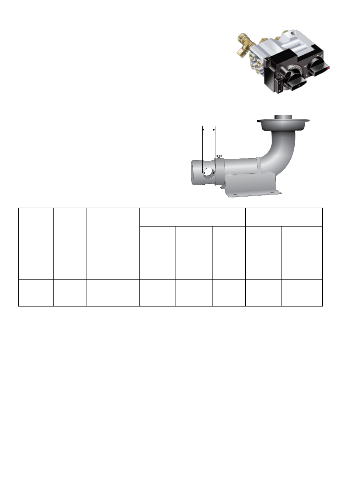
Technical Data for Harmony 35 (H35) with Mertik Maxitrol GV34 Gas
Valve.
Model Number
H35 H35001 Cast Black,
H35002 Bottle Green Enamel,
H35003 Satin Black Enamel
Standard supply appliance is configured for Natural Gas; for LPG specify at time of order
Heat Output Maximum
G20 Natural Gas 7.5kW
G31 Propane 7.1kW
Gas Input Maximum
G20 Natural Gas 8.7kW
G31 Propane 8.2kW
Net Efficiency Nat. Gas & LPG 86%
Air Collar Adjustment
Natural Gas 4mm
LPG Maximum
Free Air Requirement NIL
Maximum Output
Gas
Type
G20
Natural
Gas
G31
LPG
Fuel Effect Type Ceramic burner, ceramic logs, ceramic cubes,
ember glow fibres.
Heat Control Manual with remote control option
Ignition Type Piezo
Pilot Flame Yes
Flame Failure Yes
Gas
Pressure
mbar
20
37
Main Jet
mm
1 jet
with
4 x 1.18
1 jet
with
4 x 0.78
Pilot
Jet
27.2 0.91m3/h 18.1 mbar 86.1
22.1
Control Set to Maximum
Hourly
Flow
0.33
m3/h
High
Burner
Pressure
36.1 mbar 86.9
Net
Efficiency
%
Minimum Output
Control Set to Minimum
Hourly
Flow
0.65
m3/h
0.25
m3/h
Low Burner
Pressure
8.9 mbar
21.2 mbar
Fuel Outlet Options Top or Rear
Flue Size 180mm (7”) External Diameter
Warranty Standard 1 Year
Seasonal Efficiency
The efficiency of this appliance has been measured as specified in BS EN 613:2001 and the result is 77.9% Nat.
Gas and 80.2% LPG. The gross calorific value of the fuel has been used for this efficiency calculation, the Net
efficiency being 86% Nat. Gas and 86% LPG. The test data from which it has been calculated has been certified
by BELTEST. The efficiency value may be used in the Governments Standard Assessment Procedure (SAP) for
energy rating of dwellings.
© EUROHEAT DISTRIBUTORS (H.B.S) LTD. March 2012 E & OE Instructions Part number IN1156 Ed. E
5
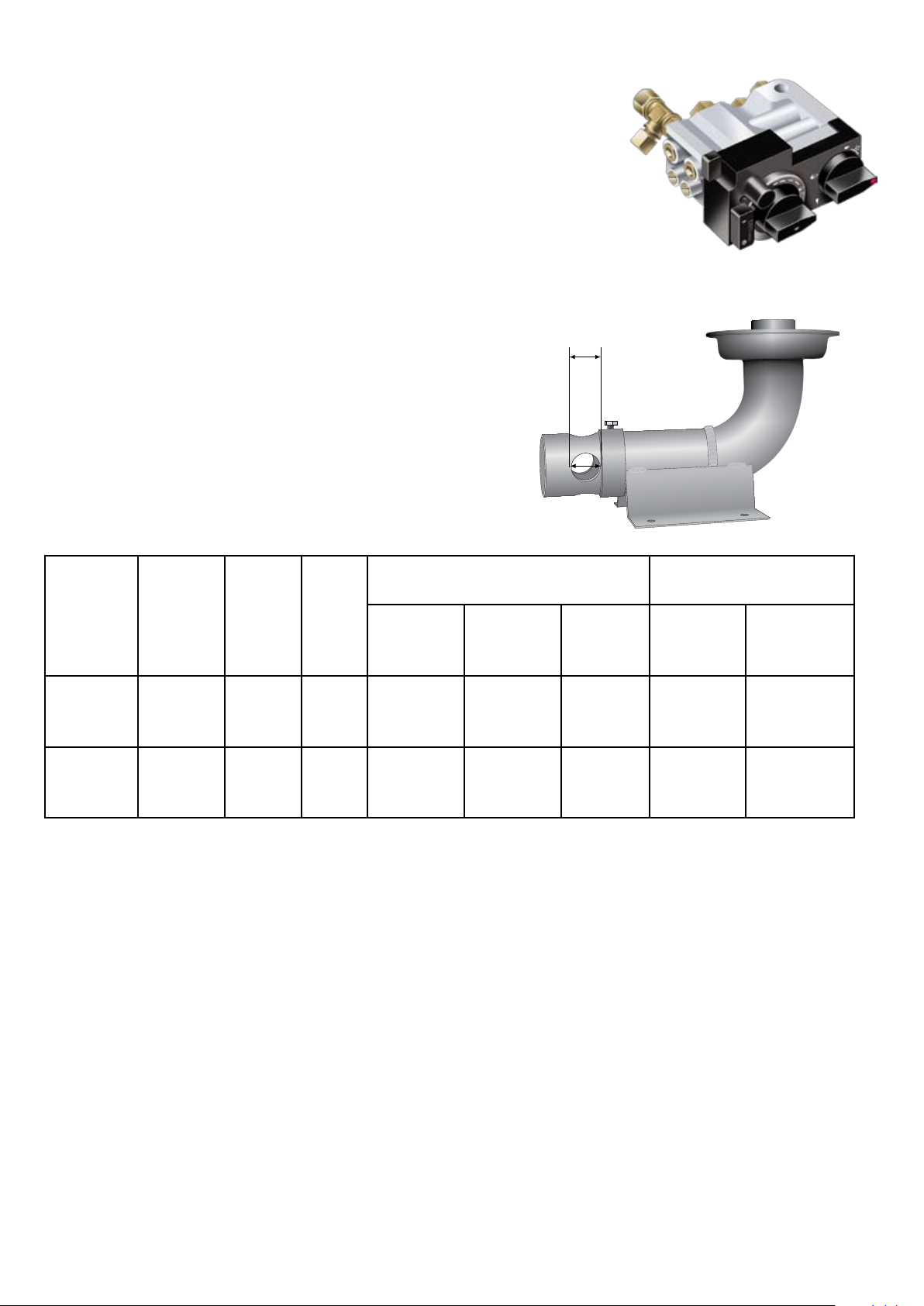
Technical Data for Harmony 45 (H45) with Mertik Maxitrol GV34 Gas
MAX
Valve.
Model Number
H45 H45002 Cast Black,
H45004 Green Enamel
H45003 Satin Black Enamel
Standard supply appliance is configured for Natural Gas; for LPG specify at time of order
Heat Output Maximum
G20 Natural Gas 8.90kW
G31 Propane 9.78kW
Gas Input Maximum
G20 Natural Gas 10.27kW
G31Propane 11.19kW
Net Efficiency Nat. Gas & LPG 87%
Air Collar Adjustment
Natural Gas Maximum
LPG Maximum
Free Air Requirement NIL
Maximum Output
Gas
Type
G20
Natural
Gas
G31
LPG
Fuel Effect Type Ceramic burner with ceramic logs, ceramic cubes,
ember glow fibres.
Heat Control Manual with remote control option
Ignition Type Piezo
Pilot Flame Yes
Flame Failure Yes
Gas
Pressure
mbar
20
37
Main Jet
mm
1 jet
with
4 x 1.29
1 jet
with
4 x 0.87
Pilot
Jet
27.2
22.1
Control Set to Maximum
Hourly
Flow
1.09
m3/h
0.46
m3/h
High
Burner
Pressure
18.4 mbar 86.7
36.5 mbar 87.4
Net
Efficiency
%
Minimum Output
Control Set to Minimum
Hourly
Flow
0..84
m3/h
0.31
m3/h
Low Burner
Pressure
10.8 mbar
16.9 mbar
Fuel Outlet Options Top or Rear (Top pre fitted)
Flue Size 180mm (7”) External Diameter
Warranty Standard 1 Year
Seasonal Efficiency
The efficiency of this appliance has been measured as specified in BS EN 613:2001 and the result is 78% Nat.
Gas and 80.7% LPG. The gross calorific value of the fuel has been used for this efficiency calculation, the Net
efficiency being 87% Nat. Gas and 87% LPG. The test data from which it has been calculated has been certified
by BELTEST. The efficiency value may be used in the Governments Standard Assessment Procedure (SAP) for
energy rating of dwellings.
© EUROHEAT DISTRIBUTORS (H.B.S) LTD. March 2012
E & OE Instructions Part number IN1156 Ed. E
6
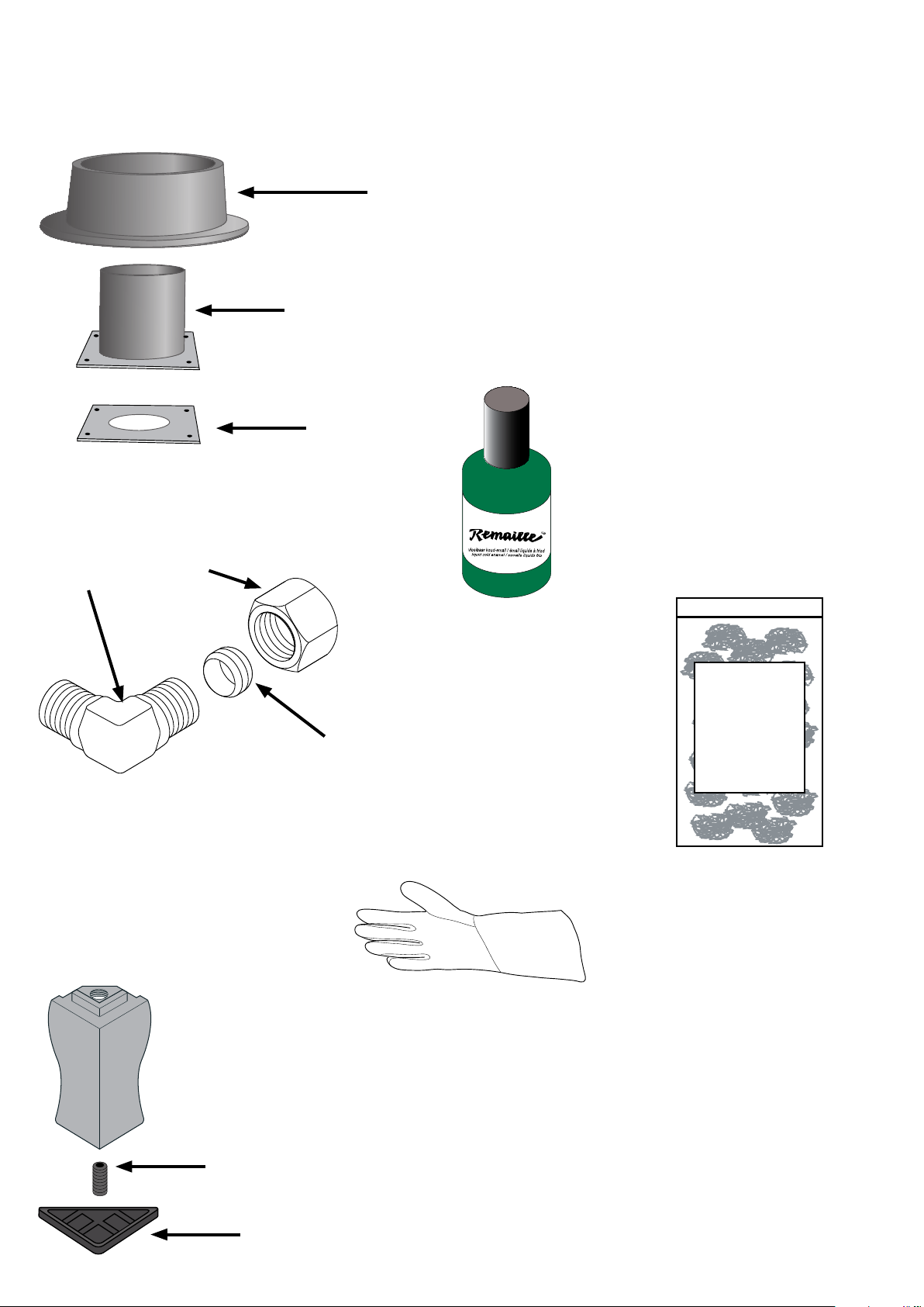
Accessories Supplied with Stove
EMBERGLOW
Platinum
Bright
Embers
Supplied with the balanced flued gas stoves are a number of installation accessories and instruction manuals.
Flue Spigot (Collar) and Choke Plate
Flue Spigot (collar)
The flue spigot (collar), inner flue pipe
and choke plate may be found either
screwed to the pallet on which the
stove is delivered, within the body of
the stove, or fitted to the stove.
Enamel Repair Touch Up
(Enamel Stoves Only)
In the plastic bag within the stove there
will be a bottle or tube of enamel touch
up which will match the enamel finish
on the stove. This can be used to repair
any minor chips on the enamel surface
of the stove.
Elbow for Gas Fitting
Elbow
Nut
Inner Flue Pipe
Choke Plate
Foot Levelling Screws and
Triangular Hearth Protectors
Grub Screw
Olive
Ember Glow
Small squares of platinum
embers which when teased
out give an ash effect with
the ceramic log or coal effect
(see page 14).
Glove
A heat proof glove is also supplied
with the stove. This is for use by the
installing and servicing engineer if
they have to open the main firebox
door when hot.
In the plastic bag within the stove there will be 4 foot
levelling grub screws and 4 plastic triangular hearth
protectors. The grub screws should be fitted to the feet
prior to installation to allow for levelling the stove on
an uneven hearth.
The plastic hearth protectors can be put under the
feet to protect the hearth when sliding the stove into
position, but should be removed unless required to
help level the stove.
Plastic Hearth Protector

© EUROHEAT DISTRIBUTORS (H.B.S) LTD. March 2012 E & OE Instructions Part number IN1156 Ed. E
7
Fraxfill (MS9045)
Fraxfill is a pliable white ceramic fibre gap fill and
should be used for sealing all the flue joints. It is
supplied for use with a sealant gun. It is odourless
and recommended for applications with operating
temperatures of 1200°C.
Balanced Flue Stove
Technical Guide
H35 Burner Brackets
The two burner brackets are fitted inside the fire box
on the left and right inner walls. They are used to
locate the ceramic burner in place. They are supplied
with 2 self tapping screws.
Installation Instructions and Balanced Flue
Technical Guide IN1105
Installation &
Servicing Instructions
Harmony 35
Harmony 45
Balanced Flue Gas Stoves
IN1156 Edition E June 2009
PART NUMBER
SERIAL NUMBER
Operating Instructions
Harmony
Stanford
Conventional Flue & Balanced Flue
Gas Stoves
IN1123 Edition G June 2009
PART NUMBER
SERIAL NUMBER
For the use of the suitably qualified engineer for the
installation and servicing of the stove.
MUST be handed to the owner of the stove.
Document No: IN1105
Operating Instructions
For the use of the person for the safe operation of the
stove.
MUST be handed to the owner of the stove.
GAS STOVE REGISTRATION
Please complete the form on pages 3 and 4 and return it with a
copy of your sales receipt from your Euroheat approved supplier
to obtain your
Registration Form
To be completed by both the owner of the stove and the installing/
THREE GOOD REASONS
Why you should have your stove commissioned.
It is vital for the longevity and efficient and safe operation of the stove to have the stove installed and
commissioned by a competent qualified heating engineer.
1. Installation
The stove should be installed by a competent qualified heating engineer, who will be conversant with the
Building Regulations and Codes of Practice current at the time of installation. Installation instructions are
supplied with the stove which contain instructions specific to the appliance.
Incorrect installation may lead to poor performance of the stove and ultimately damage to the appliance.
2. Operating
The operation of the stove should be demonstrated by a competent person, so you, as the operator, are
conversant with the operation of the controls. Instructions on the use of the controls can be found in the
operating instructions supplied with the stove.
Incorrect operation of the controls of the stove may lead to poor performance from the stove and ultimately
damage the appliance.
3. Maintenance
Routine maintenance as described in the operating instructions, supplied with the stove, should be
undertaken by a competent person.
Failure to perform the routine maintenance may adversely effect the performance of the stove and
ultimately damage the appliance.
commissioning engineer.
It MUST be returned to Euroheat for the registration to be completed.
If there are any of the above documents missing from your stove
upon delivery please contact Euroheat with the serial number of the
stove and we will immediately despatch a replacement.
© EUROHEAT DISTRIBUTORS (H.B.S) LTD. March 2012 E & OE Instructions Part number IN1156 Ed. E
8
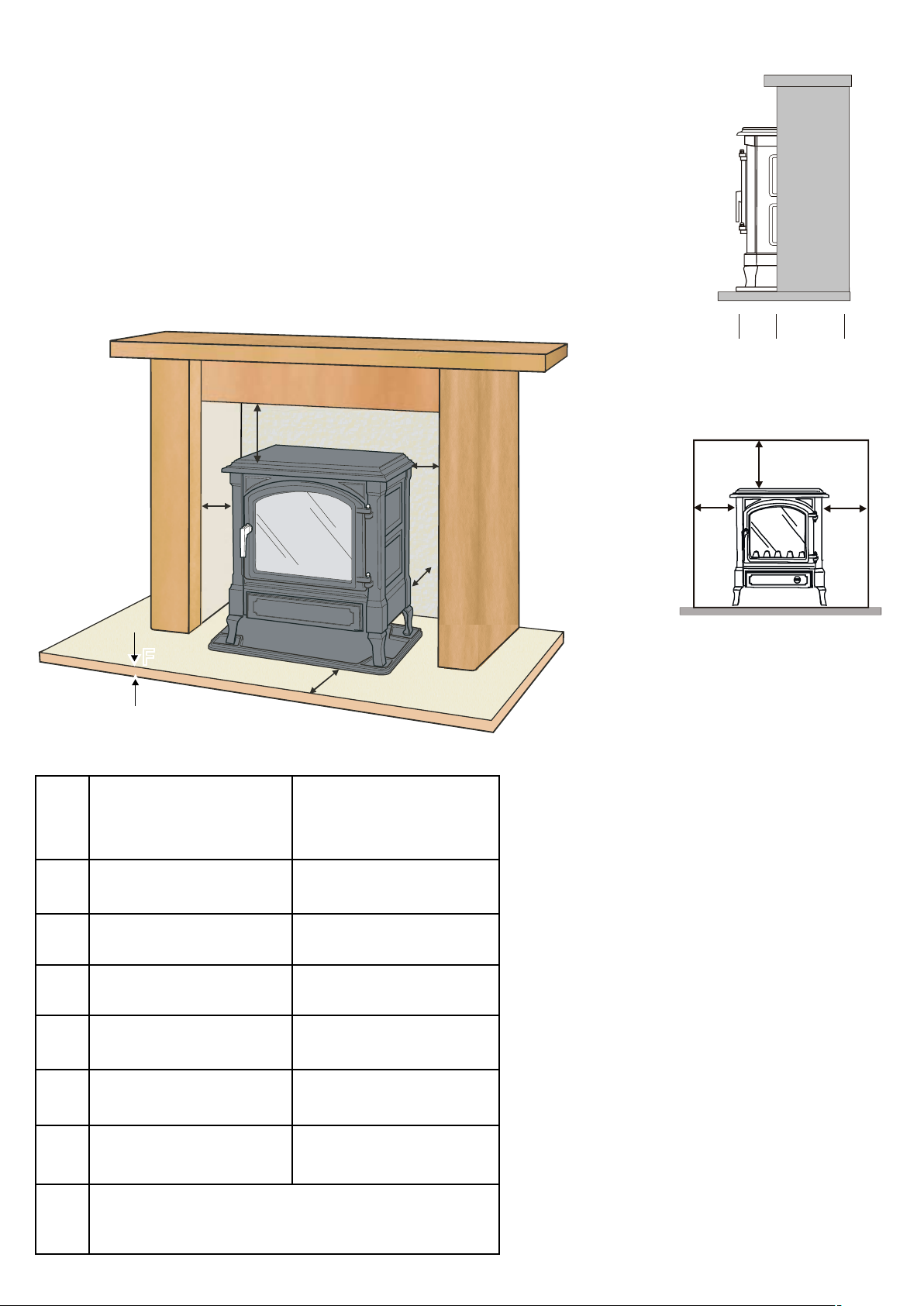
Hearth and Fireplace Requirements
A
B
D
C
E
F
1/3 2/3
1
2/3
2/3
Do not be tempted to fit the stove into an unsuitable fireplace. Beyond the requirements
of the building regulations and access to facilitate servicing the stove, providing a
setting which will complement the stove is not a luxury, it is the practicality of making
the most of an investment. A good builder will be able to transform even the most
utilitarian of fireplaces, whether altering its proportions to those of the “Golden Mean”
ideal, exposing a wooden lintel, stone or simply removing superfluous detailing for
comparatively small costs, and the result will be a pleasure for many years.
“Golden Mean”
Side Profile
“Golden Mean”
Front View
Minimum clearance
from combustible
materials
Minimum clearance
from non
combustible
materials
The stove can be placed on a combustible
floor providing it can support the weight,
A 12" 300mm** 9" 230mm
and providing a non combustible hearth
plinth with a minimum thickness of
12mm is utilized.
B 6" 150mm** 4" 100mm
** The measurements provided are
C 1" 25mm** N/A
D 2" 50mm** 2" 50mm
E 6" 150mm** 4" 100mm
F
combustable material.
Curtains and furnishings should be a minimum of
1m from the stove.
12mm of non
12mm of non
combustable material.
for guidance only.
In all installations any surrounding
flammable materials must not be allowed
to exceed 80°C or a non combustible
shield provided in accordance with
current regulations. The stove must
always stand perfectly level and have
sufficient space allowing for service
work.

© EUROHEAT DISTRIBUTORS (H.B.S) LTD. March 2012 E & OE Instructions Part number IN1156 Ed. E
9
Appliance Location
a) This stove must be mounted on a non combustible hearth. The hearth must have a minimum of
12mm non combustible material thickness. The stove can be placed on a wooden floor if it can
support the weight and as long as the hearth plinth is utilized.
b) Combustible material at the rear of the stove shall be protected against the effects of heat.
c) There must be a minimum of 300mm from the top of the stove to the underside of any combustible
shelf. Note that for every 50mm increase on clearance, the shelf may project by a further 50mm.
d) The appliance, being room sealed, may be installed in a room or space which will be used by the
occupants for sleeping.
e) Any manufactured surround used with this stove should comply with the appropriate British Standard.
f) Do not place furniture, furnishing or combustible objects within 1 metre of the stove.
If any of these conditions are not fulfilled,
DO NOT FIT THE STOVE until this has been rectified.
Installation of the Gas Supply
BS 6891
NOTE:
Ensure that the gas supply is capable of delivering the required amount of gas, and is in accordance with
the relevant current standards.
It is generally preferred to conceal the gas supply by bringing it under the hearth, or through masonry to the
side of the fireplace. Any pipe work in 8mm tube connecting the stove to the main pipe work should be kept
as short as possible with as few fittings as possible to prevent restrictions.
a) Whenever a gas pipe passes through any masonry it must have a sleeve of non combustible material
sealed at both ends to prevent the gas supply from coming in contact with masonry or lime based
mortars.
b) The gas pipe should be adequately supported over longer lengths.
c) Soft copper tubing and soft soldered joints are suitable, providing the tube is not closer than 150mm
to the stove casing i.e. the temperature must not exceed 100°C.
d) A means of isolating the gas supply to the appliance must be provided independent of any appliance
control. This may be a gas cock, ideally of the nursery type to prevent children interfering with the
gas supply.
e) Any gas tubing that has been passed through masonry, should be purged to expel any foreign
materials that may have entered the supply.
f) Care should be taken to ensure that pipe work brought through metal structures has been secured to
prevent chaffing, but allow for thermal expansion.
© EUROHEAT DISTRIBUTORS (H.B.S) LTD. March 2012 E & OE Instructions Part number IN1156 Ed. E
10
Flue Spigot Fitting
The flue can be either top or rear exit. The flue collar (spigot) is supplied attached to the pallet on which the
stove is delivered or within the body of the stove. It will need fitting to the stove depending on which flue kit
you are using, rear exit can only be used on the rear to horizontal low-level flue kit.
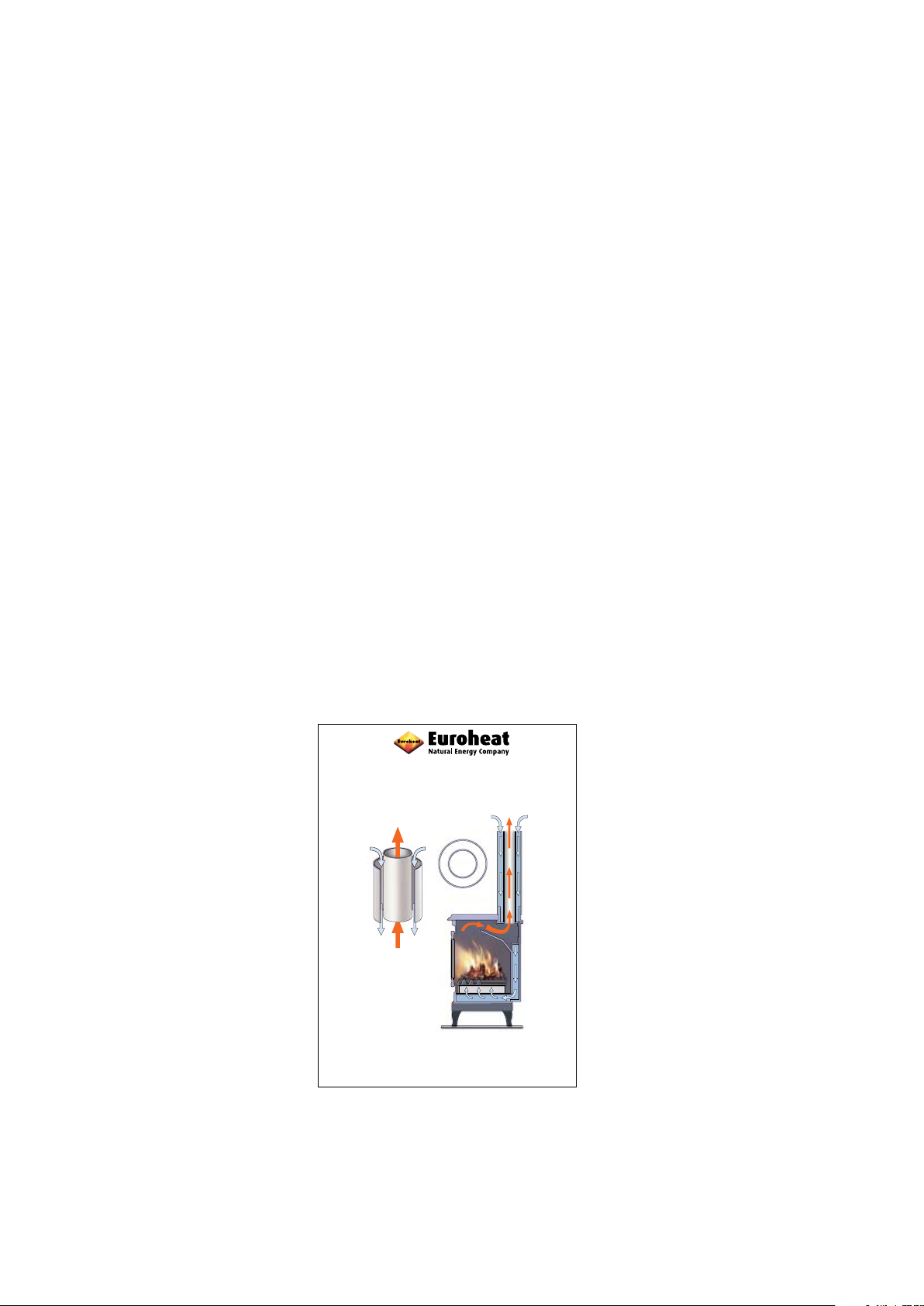
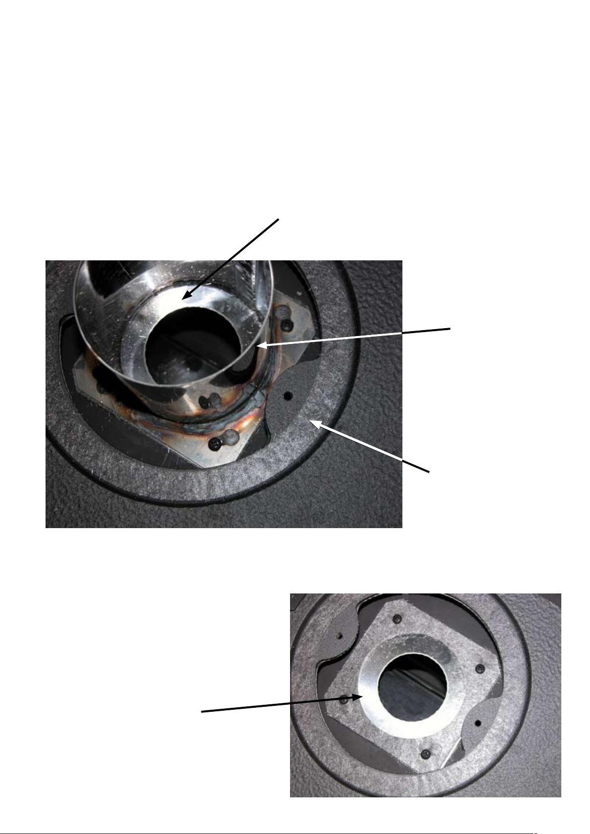
Fitting Top Flue Spigot
The stove comes with the inner top flue pipe adapter fitted to the stove with a choke plate fitted below it, see
picture below. Ensure that the choke plate fitted is correct for the gas type and flue configuration to be installed,
this information is in the Balanced Flue Stove Technical Guide: IN1105. If not replace with the correct choke
plate which can be found in the bag of installation accessories.
Choke plate
Inner flue pipe
adapter
Ceramic gasket
Inside the stove in the bag of installation accessories will be the flue spigot gasket and two M5 screws to fit the
cast iron spigot. Fit the gasket as shown above and then attach the flue spigot using the two screws.
Fitting Flue Spigot and Inner Adapter Pipe
to the Rear of the Stove.
1) Remove the inner adapter pipe, see above, and
choke plate from the top of the stove. The choke
plate is not required for the rear flue option.
Choke plate
 Loading...