

Euroheat Harmony 15, Harmony 25, Stanford 25, Harmony 35, Harmony 45 Technical Manual
...
© EUROHEAT DISTRIBUTORS (H.B.S) LTD. Technical Guide IN1105 Ed 5 May 2009
1
Balanced Flue Stove
Technical Guide
Document No: IN1105
© EUROHEAT DISTRIBUTORS (H.B.S) LTD. Technical Guide IN1105 Ed 5 May 2009
2
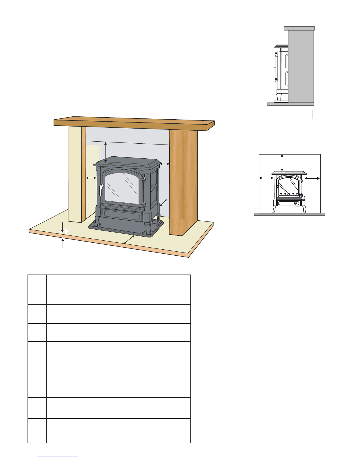
Hearth and Fireplace Requirements
Do not be tempted to fit the stove into an unsuitable fireplace. Beyond the requirements
of the building regulations and access to facilitate servicing the stove, providing a
setting which will complement the stove is not a luxury, it is the practicality of making
the most of an investment. A good builder will be able to transform even the most
utilitarian of fireplaces, whether altering its proportions to those of the “Golden Mean”
ideal, exposing a wooden lintel, stone or simply removing superfluous detailing for
comparatively small costs, and the result will be a pleasure for many years.
Minimum clearance
from combustible
materials
Minimum clearance
from non
combustible
materials
A 12" 300mm** 9" 230mm
B 6" 150mm** 4" 100mm
C 1" 25mm** N/A
D 2" 50mm** 2" 50mm
E 6" 150mm** 4" 100mm
F
12mm of non
combustable material.
12mm of non
combustable material.
Curtains and furnishings should be a minimum of
1m from the stove.
The stove can be placed on a combustible
floor providing it can support the weight,
and providing a non combustible hearth
plinth with a minimum thickness of
12mm is utilized.
** The measurements provided are
for guidance only.
In all installations any surrounding
flammable materials must not be allowed
to exceed 80°C or a non combustible
shield provided in accordance with
current regulations. The stove must
always stand perfectly level and have
sufficient space allowing for service
work.
A
B
D
C
E
F
1/3 2/3
“Golden Mean”
Side Prole
1
2/3
2/3
“Golden Mean”
Front View

© EUROHEAT DISTRIBUTORS (H.B.S) LTD. Technical Guide IN1105 Ed 5 May 2009
3
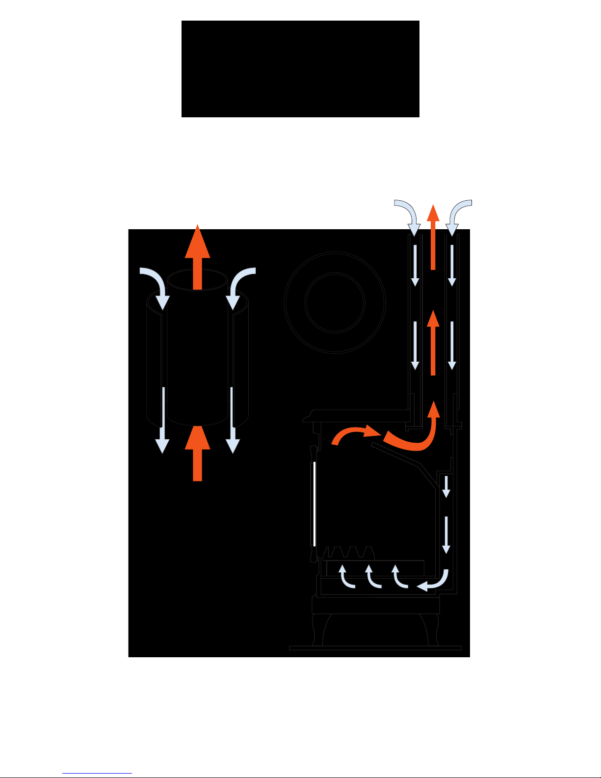
Balanced Flue Systems
A balanced flue system utilizes a double concentric pipe, the inner one taking away the products of combustion
and the outer one bringing the air supply to the stove. This system allows a gas stove to be installed where no
flue exists, and because the flue needs very little vertical height to operate, it is often possible to route the flue
through the room wall to the outside.
With all the air necessary for combustion being supplied through the outer pipe directly from the outside, the
room in which the stove is installed needs no ventilation specifically for the stove.
The balanced flue system has been designed to give a huge range of installation options, terminating either
horizontally or vertically, as illustrated in the diagram below.
Deciding on which form the balanced flue should take will very much be constrained by the termination of the
flue. Building Regulations lay out definitive guide lines for where a flue can terminate, see the diagram later in
this document, and if the building is listed there may be constraints on the position of any terminal and advice
should be sort from the appropriate regulatory authority.

© EUROHEAT DISTRIBUTORS (H.B.S) LTD. Technical Guide IN1105 Ed 5 May 2009
4
No Chimney ----- No Problem
This document will help you design and your qualified engineer install a suitable balanced flue system for your
stove. Following the simple guide lines will allow a balanced flued stove to be fitted in most situations where
a conventionally flued stove could not be fitted.
Top to Vertical High Level Flue Kit
The vertical balanced flue system is ideal in situations such as in a newly constructed
conservatory where there are no walls through which to pass a horizontal flue. The flue will
rise from the stove vertically passing through the roof where it will then terminate with a
vertical terminal.
Minimum height 2m maximum 30m.
Top to Horizontal High Level Flue Kit
It is not necessary for the stove to be situated against the outside wall through which the
flue will pass, as the versatility of the balanced flue system can allow for considerable
lengths of horizontal run of the flue.
Rear to Horizontal Low Level
The low level horizontal kit is probably the simplest method of installation and allows
you to fit the stove against any suitable outside wall in any room in your property.
Maximum horizontal length 440mm, minimum length 310mm.
Existing Chimney Adapter Kit
The flue kits are also designed to be able to utilize an existing chimney. Properties
which are designed with a high thermal efficiency may not allow an air brick
to be fitted to supply air to a stove over 7kW input, the balanced flue stove
overcomes this requirement as it is a sealed appliance.
In some cases the top section of a chimney may have been removed and the
versatility of the balanced flue system allows you to use what remains of the
chimney using the chimney adapter kit.
© EUROHEAT DISTRIBUTORS (H.B.S) LTD. Technical Guide IN1105 Ed 5 May 2009
5
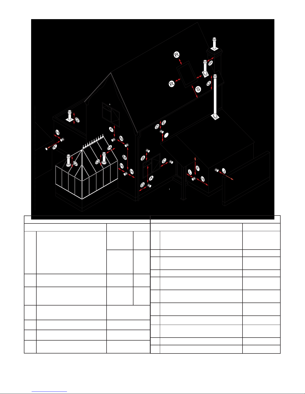
Location of Outlets from Flues Serving Gas Balanced Flue Stoves.
)
Minimum Separation Distances for Terminals in mm
Location Balanced Flue
A Below an opening Appliance
rated heat
input
0-7kw
>7-14kw
> 14-32kw
>32
300
600
1500
2000
B Above an opening (1) 0-32kw
>32kw
300
600
C Horizontally to an opening (1) 0-7kw
>7-14kw
>14kw
300
400
600
D Below gutters, soil pipes or drain
pipes
300
E Below eaves
300
F Below balcony or car port roof
600
G From a vertical drain pipe or soil
pipe
300
Minimum Separation Distances for Terminals in mm
Location Balanced Flue
H From an internal or external corner
or to a boundry alongside the
terminal
600
I Above ground,roof or balcony level 300
J From a surface or a boundary facing the
terminal
600
K From a terminal facing the terminal 600
L From an opening in the car port into the
building
1200
M Vertically from a terminal on the same
wall
1200
N Horizontally from a terminal on the
same wall
300
P From a structure on the roof
1500
Q Above the highest point of
intersection with the roof
600
R Flue should not penetrate shaded area 600
S Flue should not penetrate shaded area
200
Note (1)
An opening means an openable element, such as an openable window, or a fixed opening such as an air
vent. However, in addition, the outlet should not be nearer than 300mm to an opening into the building fabric
formed for the purpose of accommodating a built in element, such as a window frame.
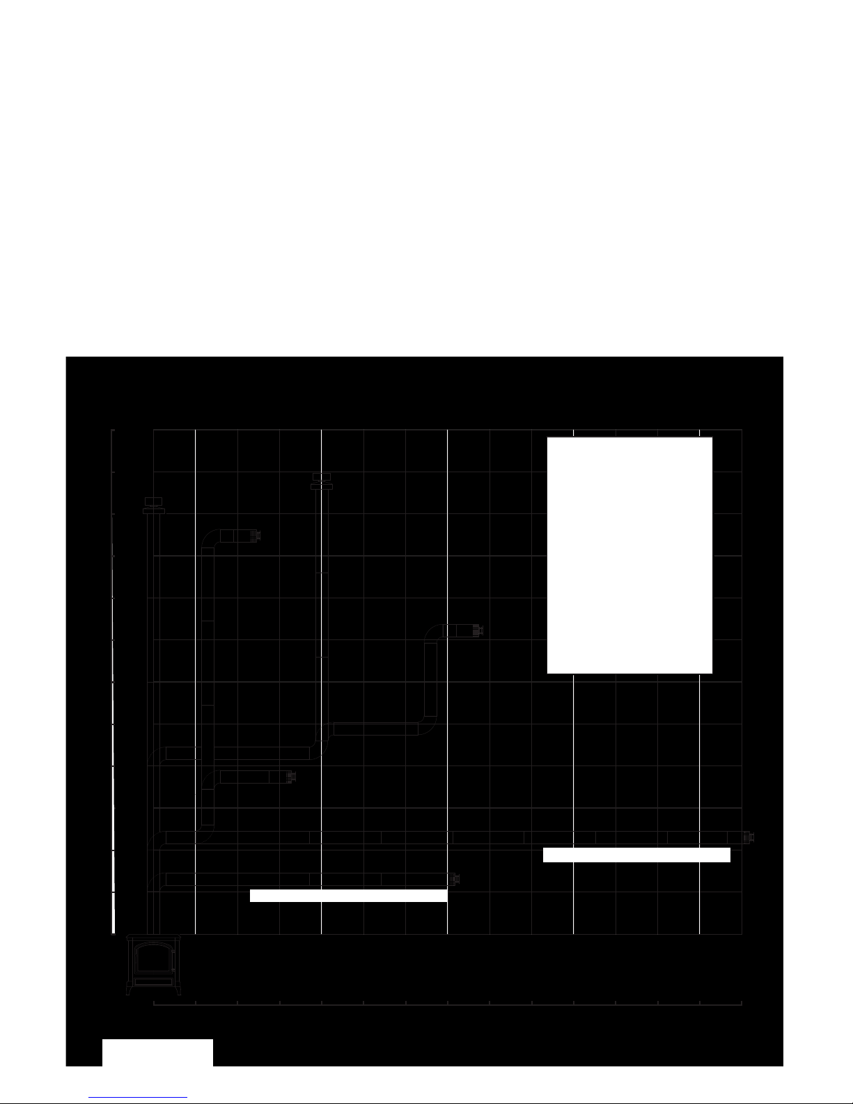
Calculating Flue Aspect Ratios
The stove operates correctly only with air flow induced by the flue system being within the defined parameters.
To achieve these, the vertical elements of the flue, which induce flue draught and increase the air supply to the
stove, must be balanced against the horizontal elements of the flue, which offer resistance to flue draught and
reduce the air supply to the stove.
The ratio of vertical to horizontal lengths must be calculated to ensure the correct flue draught will be induced
by the proposed flue.
The difference in height between the top of the stove and the bottom of the terminal determines the vertical
height to be used in the calculation. The flue run may necessitate the vertical elements to be separated by
several horizontal runs, this is not important, only the total height gain is needed.
The horizontal length is often more tedious to determine, but again, it is the total length which needs to be
determined, regardless of their being continuous or in stages. Any 90 degree change of direction within the
flue will offer resistance to flue draught and each change of direction will offer the same resistance to the flue
draught as a horizontal run of 1000mm. For every 45 degree change in direction the resistance is that of a
horizontal run of 500mm.
0
0 0.5 1.0 1.5 2.0 2.5 3.0 3.5 4.0 4.5 5.0 5.5 6.0 6.5 7.0
0.5
1.0
1.5
2.0
2.5
3.0
3.5
4.0
4.5
5.0
5.5
6.0
BALANCED FLUE ASPECT RATIO DYNAMICS ILLUSTRATED
For 1m vertical rise a flue may have a maximum horizontal run of 7m.
For each 90 degree bend introduced the horizontal run must be reduced by 1m.
For each 45 degree bend introduced the horizontal run must be reduced by 500mm.
.5m vertical = 3.5m horizontal max.
1m vertical = 7m horizontal max.
Depending on
which direction your
flue configuration
will take and the
model of the stove,
a flue reduction
plate (FRP) may
or may not be
required.
See pages 24 & 25
for details.
© EUROHEAT DISTRIBUTORS (H.B.S) LTD. Technical Guide IN1105 Ed 5 May 2009
6
0
0.5
1.0
0
0 0.5 1.0 1.5 2.0 2.5 3.0 3.5 4.0 4.5 5.0
0.5
1.0
1.5
1.5
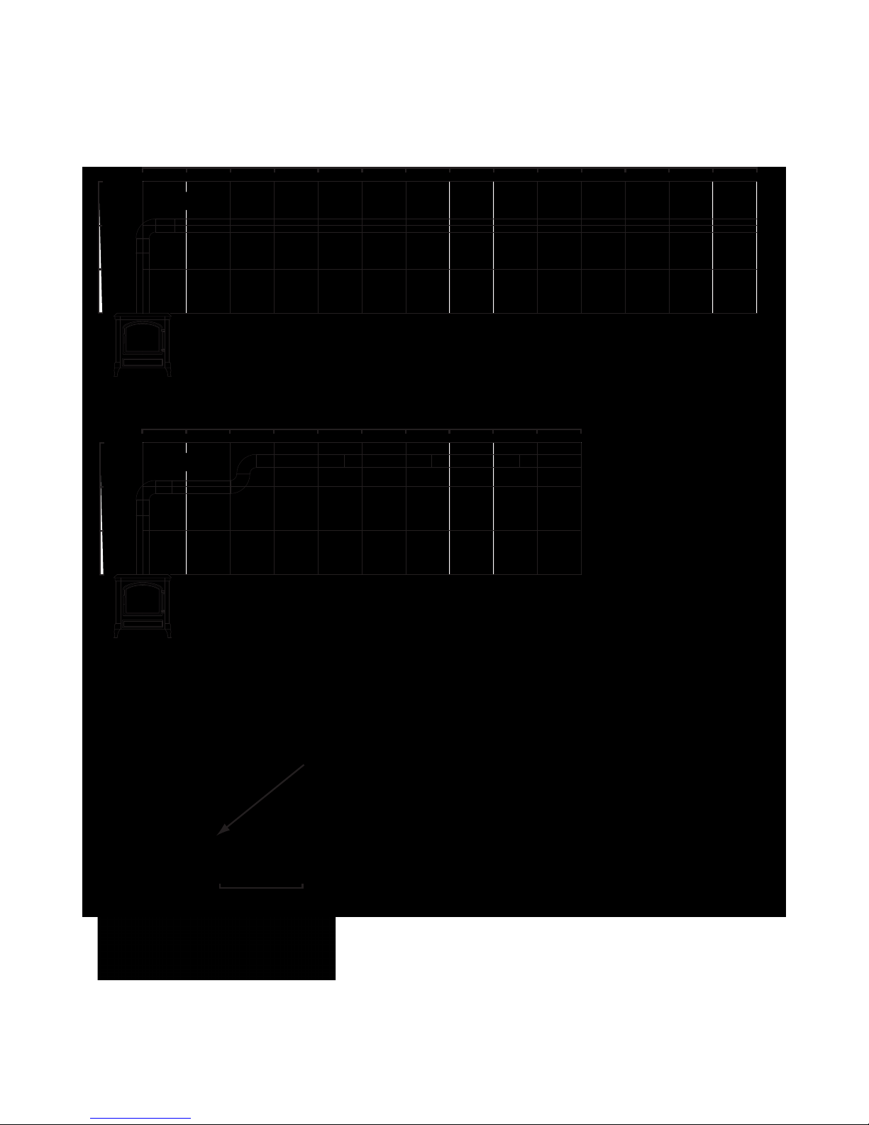
For a 1m vertical rise a flue can have a maximum of 7m horizontal length.
Each additional 90 degree bend creates a draught resistance equal to 1m
of horizontal length.
Therefore in example 'B' the introduction of 2 x 90 degree bends,
in a horizontal plain, reduces the maximum horizontal length by 2m.
Example 'A'
Example 'B'
Example 'C'
0 0.5 1.0 1.5 2.0 2.5 3.0 3.5 4.0 4.5 5.0 5.5 6.0 6.5 7.0
0
Min 310mm/ Max 440mm
The rear exit flue may have a maximum horizontal run of 440mm
from the flue spigot, the minimum length 310mm.
Flue spigot
Basic Principle of Balanced Flue Ratios Illustrated
© EUROHEAT DISTRIBUTORS (H.B.S) LTD. Technical Guide IN1105 Ed 5 May 2009
7
Top to Horizontal High Level
Rear to Horizontal Low Level

© EUROHEAT DISTRIBUTORS (H.B.S) LTD. Technical Guide IN1105 Ed 5 May 2009
8
Example 1: Top to Horizontal High Level Kit
Using the standard top to horizontal high level flue kit only.
Standard kit starter
length T1
Standard kit
terminal length T2
Sleeve kit
(accessory)
Ceramic rope or
Fraxll sealant to
prevent draughts
Standard kit 90
degree long bend
Minimum
50mm
Cavity wall
12mm
Solid wall
MM
Description Part No.
Top to
HorizontalHigh
Level Kit
150mm 180mm
MS91102 MS91103
Sleeve liner MS91065 MS91066
Terminal
guard
FP767 FP767
Closure bezel MS91033 MS91040
Components used
Closure
bezel
Terminal guard
(accessory)
The closure
bezel fits around
the flue pipe
covering the
hole through
a solid wall
giving the
installation
a clean finish
both inside and
outside.
© EUROHEAT DISTRIBUTORS (H.B.S) LTD. Technical Guide IN1105 Ed 5 May 2009
9
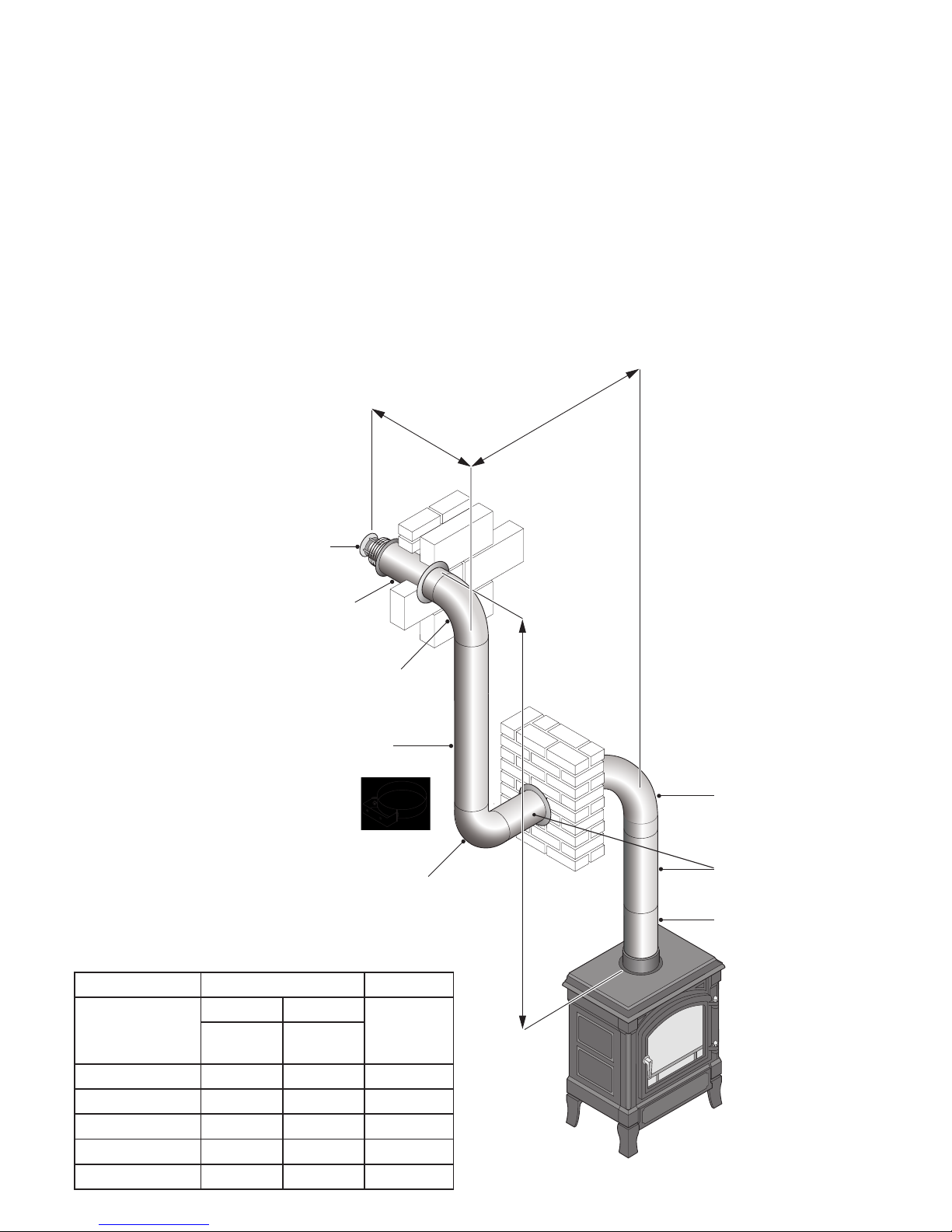
Example 2: Top to Horizontal High Level Kit
Taking the attached diagram as an example we can calculate the flue parameters for a top to horizontal flue
system.
Total Height = A
Total Horizontal = B
In this example
A = 2.8 Metres B = 1.75 Metres
Three x 90 degree bends have been used one of which (C) is the standard supply kit bend. This bend is ignored
from the calculation as it is presumed it will always be used. The two remaining 90 degree bends increase the
horizontal length by two metres.
(one metre extra horizontal length per additional 90 degree bend).
Total Height A = 2.8 Metres
Total Horizontal B = 1.0 Metres
In this example there is sufficient vertical rise for the horizontal run, as shown in the graph on page 6.
Standard kit
terminal length
T2
Standard kit
long 90
O
bend
Accessory 250mm
length within wall
Accessory short
90
O
bend
Accessory short
90
O
bend
Accessory
500mm length
Standard kit
starter length
T1
Accessory 1metre length
Wall band
B
B
B+B= Total Horizontal
AA Total height
Description Part No. Quantity
Top to
HorizontalHigh
Level Kit
150mm 180mm
1
MS91102 MS91103
1 metre length MS91028 MS91034 1
500mm length MS91029 MS91035 2
250mm length MS91030 MS91036 1
90° short bend MS91031 MS91037 2
Wall band MS91052 MS91053 1
Components used

© EUROHEAT DISTRIBUTORS (H.B.S) LTD. Technical Guide IN1105 Ed 5 May 2009
10
Example 3: Top to Vertical High Level Kit
The ratio of vertical to horizontal lengths must be calculated to ensure the correct flue draught will be induced
by the proposed flue. Taking the ratio diagram as an example we can calculate the flue parameters for a top
to vertical flue system.
Total Height = A
Total Horizontal = B
In this example
A = 3.5 Metres B = 1.5 Metres
Two x 90deg bends have been used. The two 90 degree bends increase the horizontal length by two metres.
(One metre extra horizontal length per additional 90 degree bend).
Total height A = 3.5 Metres
Total Horizontal B =0.9 Metres
In this example there is sufficient vertical rise for the horizontal run, as shown in the illustration on page 6.
GhUbXUfX_]h
hYfa]bU`
FccZZ`Ug\]b[
5WWYggcfm%
aYhfY`Yb[h\
5WWYggcfm
)$$aa`Yb[h\
5WWYggcfmg\cfh
-$VYbX
5WWYggcfmg\cfh
-$VYbX
KU``VUbX
KU``VUbX
6
5WWYggcfm
)$$aa`Yb[h\
5
HchU`\cf]ncbhU`
`Yb[h\
HchU`jYfh]WU`
\Y][\h
GhUbXUfX_]h
ghUfhYf`Yb[h\
H%
Description Part No. Quantity
Top to Vertical
High Level Kit
150mm 180mm
1
MS91100 MS91101
1 metre length MS91028 MS91034 1
500mm length MS91029 MS91035 3
90° short bend MS91031 MS91037 2
Wall band MS91052 MS91053 2
Components used
(accessory)
(accessory)
 Loading...