

Euroheat Harmony 13, Harmony 23, Harmony 33, Harmony 43, Stanford 13 Servicing Instructions
...Page 1

Euroheat Distributors (H.B.S.) Ltd.,
Unit 2, Court Farm Business Park,
Bishops Frome,
Worcestershire,
WR6 5AY.
Servicing Instructions
Harmony 13,23,33,43
Stanford 13,23,33,43
Stanford SP23,SP33
Multifuel & Wood Stoves
Euroheat Distributors
(H.B.S.) Ltd.,
Unit 2, Court Farm
Business Park,
Bishops Frome,
Worcestershire,
WR6 5AY.
© EUROHEAT DISTRIBUTORS (H.B.S) LTD. March 2008 E & OE Instructions Part number IN1195 Edition A
1
Page 2

© EUROHEAT DISTRIBUTORS (H.B.S) LTD. March 2008 E & OE Instructions Part number IN1195 Edition A
2
INTRODUCTION
Servicing your stove should not be seen as a chore but rather the means to getting the most efficient use and
increasing the life of the stove. A badly maintained stove will run inefficiently, so you will burn more fuel, and
if left unmaintained for a period could seriously damage the component parts within the stove which will then
need replacing.
This booklet details the aspects of servicing and routine maintenance required.
Other documents obtainable on request from Euroheat
IN1086 Technical Guide. The Multifuel Stove.
IN1087 Technical Guide. The Flue.
These guides are available by post by from Euroheat or our web site
www.euroheat.co.uk
Spares may be purchased from:
Your Local Euroheat Supplier
The Euroheat Web Site: www.euroheat.co.uk
Euroheat Spares Department:
Email: [email protected]
Tel: 01885 491126
Fax: 01885 491106
The service engineer is responsible under the health and safety at work act 1974 vi the caustic nature of fire
cement and the possibility of disturbing asbestos and other materials such as ceramic in existing installations
and to suggest appropriate protection to be given to the person (s) carrying out the servicing. The complete
servicing must be carried out with due reference to the British Standards, Codes of Practice and Building
Regulations relevant to the fuel type installed, and the manufacturers installation instructions.
This document is a general service guide only. It does not replace the installation instructions or building
regulations. No servicing should be undertaken unless the engineer is suitably qualified.
Page 3

© EUROHEAT DISTRIBUTORS (H.B.S) LTD. March 2008 E & OE Instructions Part number IN1195 Edition A
3
Maintenance schedule
1. After the First Two Weeks of Operation
Check that the doors are sealing properly when shut and adjust the handle latches accordingly. See pages 9
and 10.
2. Weekly
A) Remove any ash that may have fallen from the ash pan in the stove under the grate. If this is allowed to
build up it can foul the ash pan which may make closing the ash pan door difficult and allow air to leak into
the stove from the ash pan door seal.
B) Check the operation of the riddle mechanism to ensure that it has not become jammed. If it has become
hard to riddle, remove all ash from the fire bed and ensure that there is no clinker, nails or screws obstructing
the movement of the grate.
3. Monthly
A) Visually check the condition of the door and glass seals, and if they have become frayed or are coming loose
they may need replacing.
4. Every 3 Months
A) Remove the top two baffles, see pages 13 to 18, and remove any soot and debris that may have accumulated
above them. This may have to be done more regularly if wet wood has been burned or poor quality smokeless
fuel or anthracite.
B) Check the operation of the plexus and lubricate if necessary.
C) Check that the doors are sealing properly when shut and adjust the handle latches accordingly. See pages
10 and 11.
5. At the End of the Heating Season (Summer Shut Down)
A) Have the chimney swept and inspected by an approved (NACS) chimney sweep. The chimney may need
sweeping more regularly dependant upon the fuel used and how often the stove is used.
B) Do all the above in the weekly, monthly and 3 monthly procedure.
C) Clean the inside of the stove removing all the cast iron components and remove any ash that may be behind
them. Inspect the internal cast iron parts of the stove and replace if necessary. Before replacing them spray the
stainless steel combustion chamber with a water repellent spray, e.g. WD40.
D) Lubricate the door handle shafts with a lubricant such as WD40.
6. At the Start of the Heating Season
A) Check the door rope seals so as to ensure an air tight seal. See page 9.
B) Check the operation of the riddle mechanism and the plexus control ensuring that the flaps open and close
freely.
C) Light a small fire and ensure all the smoke is being vented up the chimney once the flue has reached
working temperature. If there is any sign of the flue or stove not working as it did previously or smoke is being
emmitted into the room then contact your NACS chimney sweep.
Page 4
© EUROHEAT DISTRIBUTORS (H.B.S) LTD. March 2008 E & OE Instructions Part number IN1195 Edition A
4
Cleaning the Stove
Cleaning the Glass
Properly operated, with the correct fuel, your glass will remain clean. Slight staining may appear when the
stove is lit and below its operating temperature. This will normally clear as the stove’s temperature rises.
If it becomes necessary to clean the glass by hand do not attempt to do so unless the stove is cold. Proprietary
glass cleaning agents are available but they must specifically state its suitability for ceramic stove glass before
being used because the glass in your stove is not ordinary glass and may be damaged with an unsuitable
cleaner.
Newspaper moistened with water to which a little vinegar has been added will normally remove most staining,
but for really stubborn marks, gentle polishing with fine steel wool lubricated with a few drops of dish washing
detergent will need to be employed. Great care must be taken not to clean the glass too vigorously as particles
of grit may have adhered with the stain and these could cause scratching if dragged across the glass. However
well the stove burns it will eventually become necessary to clean the glass, but if cleaning becomes necessary
too often we advise you to review your operating procedures to determine whether cleaner and more efficient
combustion can be achieved (only burn dry seasoned wood).
The Stove Body
Dusting the stove may be carried out when the stove is at its minimum heat output temperature, using light
strokes of a real bristle paint brush. Thorough cleaning, or any attempt to remove marks on the stove body must
only be done when the stove is cold. Stoves with an enamel finish should be cleaned with a damp cloth, or very
gentle use of a cleaner recommended for enamel finishes. It should be noted that even approved cleaners will
damage the highly polished finish of the stove if used too vigorously. All traces of the cleaner must be removed
before the stove is lit and no finishing polishes must ever be used as these will leave unsightly streaks on the
stove when it becomes hot.
Stoves with a cast black finish should never be cleaned with a cloth as the texture of the paint will abrade and
collect lint from the cloth which will be almost impossible to remove. Vigorous brushing with a stiff real bristle
paint brush will remove all dust, but where the paint is marked, the stains are better obliterated with a spray
of suitable stove paint rather than attempts made to clean them off. Suitable paint may be purchased from a
stove shop or direct from Euroheat.
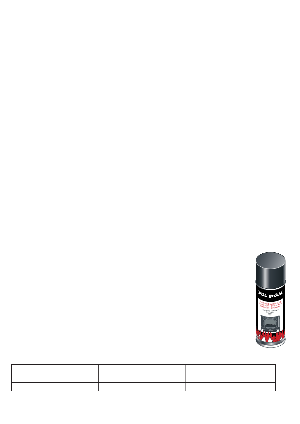
Re-spraying the Stove Surface
Remove any dust and dirt with a stiff brush or vacuum with a brush attachment. Mask off any
areas of the stove you do not wish to re-spray and the area surrounding the stove. The door
handles and doors can be removed if required, see the section on hinge pin removal and door
handle adjustment, page 6 and 9.
Shake the can vigorously for a minute to mix the contents and apply the paint thinly and evenly
over the surface, avoid over application as this will produce unsightly runs on the surface. It is
better to use a few thin coats than one thick one.
Order Numbers for Spray Paint
Surface to be Sprayed Part Number Size of Can
Cast iron body 40785 200ml
Rear heat shield 60429 400ml
Page 5

© EUROHEAT DISTRIBUTORS (H.B.S) LTD. March 2008 E & OE Instructions Part number IN1195 Edition A
5
Repair of the Enamel Surface
The enamel surface of the stove may become chipped if it is hit with a
hard object such as a coal shovel or operating tool. Suitable cold enamel
touch up paint may be purchased.
To prepare the surface remove any loose or flaking enamel finish and
brush or vacuum the area to remove any dust and dirt. If the touch up is
supplied in a bottle shake vigorously for a minute to mix the contents. If
supplied in a tube squeeze out some of the contents onto a clean sheet of
paper and mix with a match stick as it may have become separated in the
tube. Apply a thin layer of touch up to the surface allowing it to dry before
applying further layers to build the surface up to the surrounding enamels
height. Leave to dry before firing the stove.
If your stove has an enamel finish you will notice, after the stove has been used several times, it develops
what is called a “crackle” pattern in the enamelling. This is caused by the different expansion rates between
the enamel and the cast iron, it is normal and should not be regarded as a fault or indicating that the stove is
beginning to shed its finish.
If the enamel surface in an area has been too badly damaged to touch up then all the panels on the stove can
be removed and replaced. See the web site for part numbers and prices.
Order Numbers for Touch Up Paint
Enamel Colour Part Number
Satin black enamel 27440
Bottle green enamel 27437
Brass Fittings
Any proprietary brass cleaner may be used to clean the brass on the stove, but care must be taken to ensure
the polish does not come into contact with the stove enamel or the black cast finish, where it will leave a
stain.
Nickel and Black Haematite Fittings
Any proprietary chrome or aluminium cleaner may be used to clean the decorative fittings on the stove, but
care must be taken to ensure the polish does not come into contact with the stove enamel or the black cast
finish, where it will leave a stain.
The Flue
Even if your flue is correctly lined it is advisable to run your stove at a high setting to thoroughly warm the flue
periodically and ensure it is swept regularly. If the stove has not been used for some time it will be necessary
to ensure the flue has not been blocked with twigs from home building birds or blocked with other obstructions
before the stove is lit. Lighting a small piece of paper within the stove will determine the flue’s ability to
remove any products of combustion.
National Chimney Sweeps Association
Telephone: 01785 811732
The Solid Fuel Association
Telephone: 0845 6014406
Page 6
© EUROHEAT DISTRIBUTORS (H.B.S) LTD. March 2008 E & OE Instructions Part number IN1195 Edition A
6
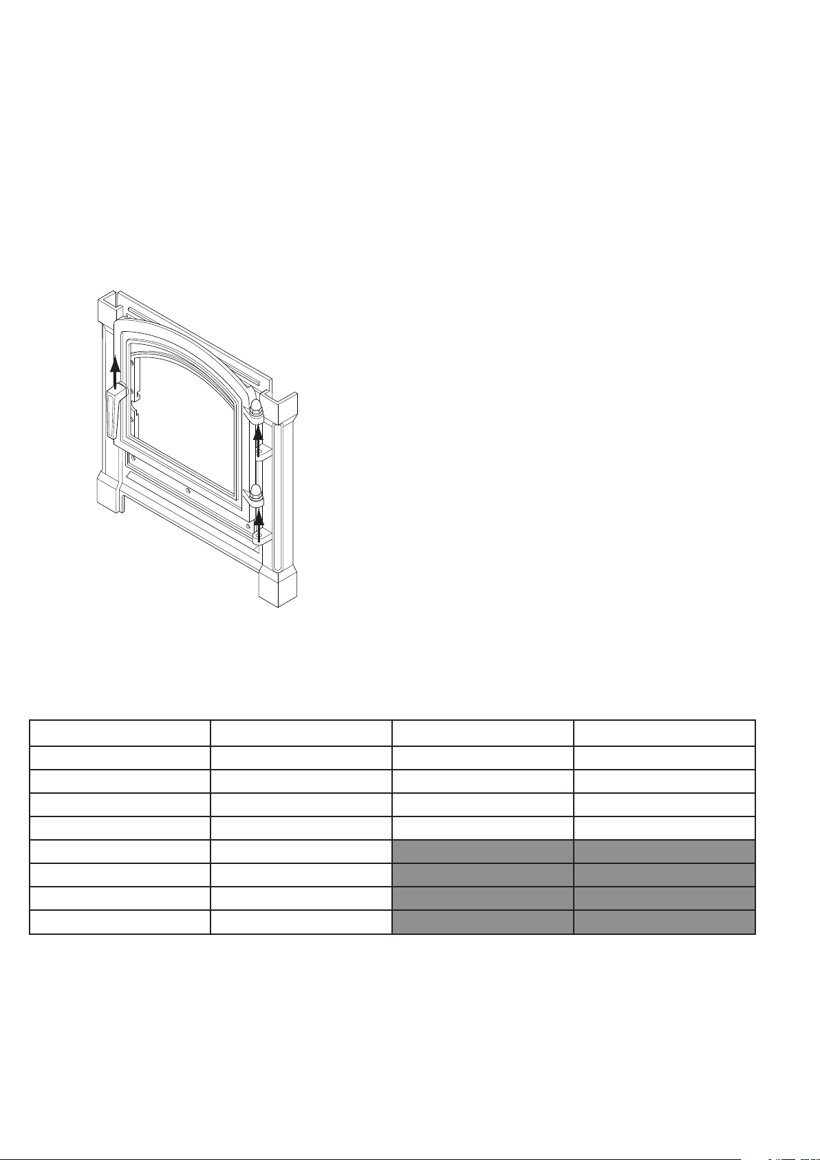
Front Door Removal
To remove the door undo the handle and open the door.
Lift the door and hinge pins straight up holding the hinge side of the door and the handle. If the hinge pins do
not lift up easily, then by swinging the door into and away from the body of the stove whilst lifting should then
free the hinge pins to rise upwards.
Reverse the procedure to refit ensuring that if there were any washers fitted they are also refitted fitted.
Open door and lift
upwards holding
hinge side of door and
the handle.
Model Hinge Pin Washer Domed Nut
H13 19915 17496 12430
H23 18906 17496 12430
H33 18906 17496 12430
H43 18906 17496 12430
S13 31848
S23 31848
S33 31848
SP23/33 31848
Page 7
© EUROHEAT DISTRIBUTORS (H.B.S) LTD. March 2008 E & OE Instructions Part number IN1195 Edition A
7
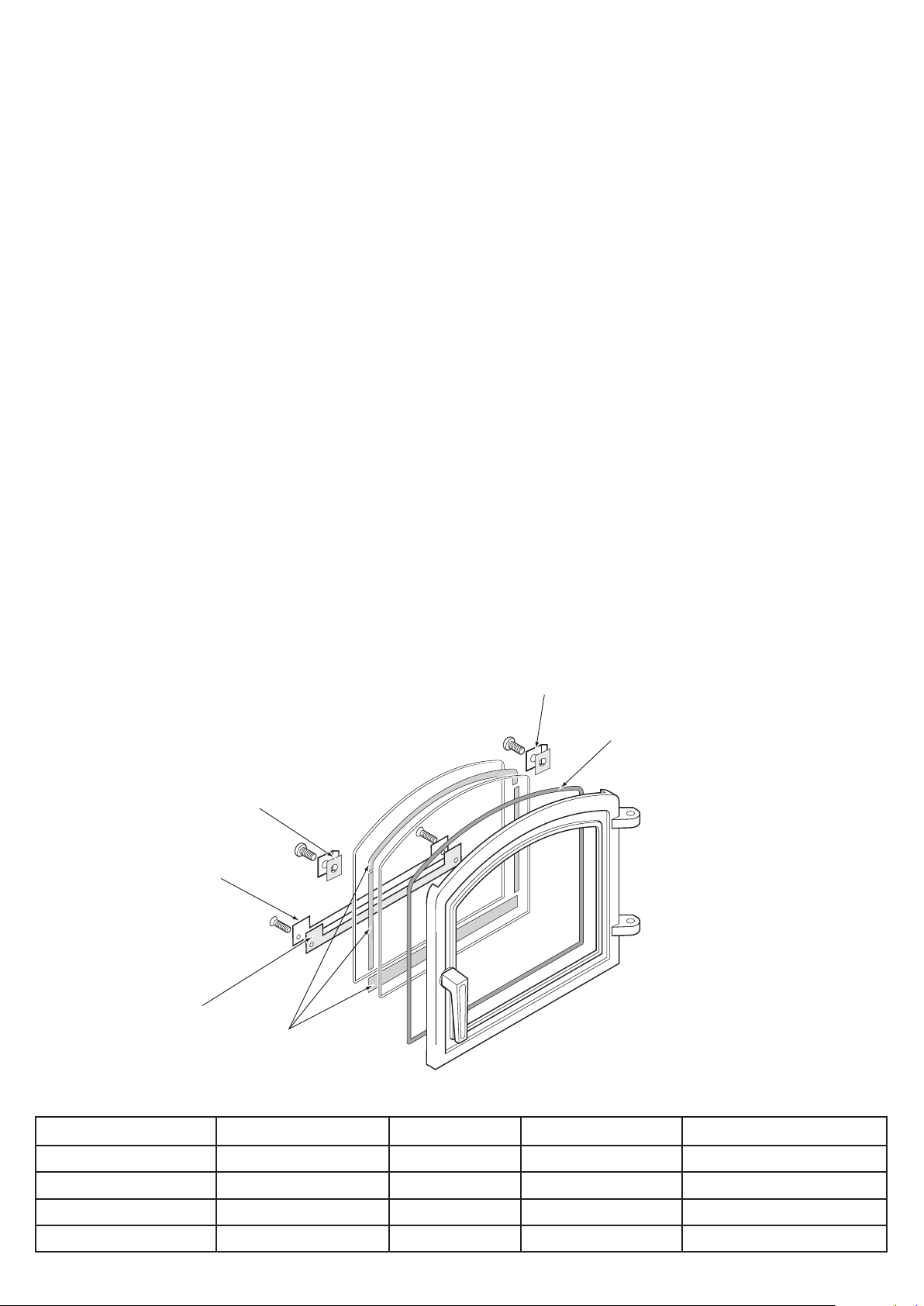
Glass and Glass Seal Set Replacement
Ceramic rope gasket
fitted into groove in the
door
Ceramic seal between
inner and outer glass
panels
Lower outer
ceramic seal
Lower glass clip
Glass clip
ceramic pad
Glass clip
When replacing the glass on any of the stove models supplied by Euroheat the glass seal should also be
replaced. Failure to do so could cause damage to the glass or allow air into the stove in an uncontrolled manner
which may be detrimental to the performance of the stove.
The seals should be changed annually and replaced if they have become damaged or show signs of leakage.
The seals may be either a rope seal and or a ceramic fibre gasket. In all cases these are interchangeable.
It may be easier to replace the glass by removal of the door and lying it down on a stable flat surface.
Glass and Seal Set Removal
Undo the four glass clip screws and carefully lift off the glass clips and panels from the door frame. With a blunt
instrument such as a screwdriver scrape away the old ceramic glass seal from the door frame. If it has a rope
seal which needs to be renewed pull out the old rope seal and with a blunt instrument such as a screwdriver
scrape away the old rope glue and any dirt. Clean away any remaining residue with a wire brush.
Always use new seals do not re-use any of the seals previously fitted.
Fit the inner door to glass seal, either rope or ceramic fibre gasket, and lay the first panel of glass onto it. Then
lay the ceramic gasket for the two glass panels onto the first glass panel and then place the second panel on
top of the seal. Put the glass clip gaskets in the glass clips and push the retaining screw or bolt through the
glass clip and seal. Screw these to the door frame so as to hold the glass panels in place.
Do not over tighten the screws or bolts as this could cause the glass to crack when the stove gets hot. Ensure
that when you push down on the glass near the glass clips there is some movement to allow for the differing
expansion coefficients of the different materials.
Harmony Stoves
Stove Model Seal Set Glass Upper Clip Lower Clip
Harmony 13 MS2308 32724 43438 & 43437 43344
Harmony 23 MS2306 MS0775 44143 x 2 44267
Harmony 33 MS2305 MS0771 44212 x 2 44213
Harmony 43 MS2316 MS0779 44212 x 2 43904
Page 8

© EUROHEAT DISTRIBUTORS (H.B.S) LTD. March 2008 E & OE Instructions Part number IN1195 Edition A
8
Lower Glass Clip
Glass Clip SealGlass Clip SealGlass Clip Seal
Upper Glass Clip
Glass Clip Seal
Glass panels
Glass Seal
Glass Seal
Stanford Stoves
Order Numbers for Glass and Glass Seal Kits
Stove Model Seal Set Glass Upper Clip Lower Clip
Stanford 13 MS2307 MS0782 43345 43419
Stanford 23 MS2309 MS0776 44367 44366
Stanford 33 MS2304 MS0773 43314 43313
Stanford 43 44159 43868 43906 43904
SP23 MS2309 MS0776 44367 44366
SP33 MS2304 MS0773 43314 43313
NEVER CLAMP THE GLASS CLIPS DOWN TIGHT ONTO THE GLASS OR FIT THE GLASS CLIPS WITHOUT
THE CERAMIC PADS UNDERNEATH AS THIS MAY LEAD TO THE GLASS BREAKING.
Ash Pan Door with Ceramic Rope Seal
Note the position of the joint at the top
of the door.
Latch adjustment screw
which can be adjusted to
maintain an air tight seal
as the rope seal beds in.
Page 9

© EUROHEAT DISTRIBUTORS (H.B.S) LTD. March 2008 E & OE Instructions Part number IN1195 Edition A
9
Rope Seal Replacement for Front and Ash Pan Doors
Replace the door rope seals at least every two years and adjust the door latches regularly to maintain a
good air tight seal
The ceramic rope seals on the two doors need inspecting regularly and replacing when they become damaged
or when the adjustment of the door handles will not maintain an air tight seal. To check if the seals are tight
you need a piece of standard A4 copier paper, cut it in half and then fold it in half. Shut it into the door in
various places with the door handle closed. If the seal holds the paper tight and it is difficult to withdraw it
then the seal is good. If when it is pulled it slides out easily then the door handles will need adjustment or the
rope seal will require replacement.
Failure to maintain a good seal will allow uncontrolled air to enter the stove. This can cause over firing,
excess heat, which can damage the internal components of the stove. Symptoms of this are a stove burning
uncontrollably even when the air inlets are shut down. The glass becoming dirty due to cold air passing over it
causing soot particles to adhere to the cold glass surface.
Order Numbers for Door Rope Seal Kits
Stove Model Part No.
Harmony 13 RO176
Harmony 23 RO177
Removal of Old Rope Seal
Harmony 33 RO177
Pull the old rope seal from the rope groove, it may require a flat
bladed screw driver to lift it from the groove. Clean the groove of all
accumulated dirt and old rope glue, a flat bladed screw driver and
wire brush are recommended to clean the groove.
Fitting New Rope Seal
The ceramic rope in the seal set kits it cut to an approximate length,
as the kits fit various stoves. Run the rope around the rope groove and cut it to the required length. Remove
it from the groove and apply a bead of rope glue into the rope groove. Push the rope back into the groove
ensuring that the joint is at the top and fitting tightly together. Close the door and adjust the handle latch
accordingly.
Rope seal groove
Harmony 43 RO177
Stanford 13 RO176
Stanford 23 RO177
Stanford 33 RO177
Stanford 43 RO177
SP23 RO177
SP33 RO177
Rope joint top
centre of door
Ceramic rope seal
Page 10

© EUROHEAT DISTRIBUTORS (H.B.S) LTD. March 2008 E & OE Instructions Part number IN1195 Edition A
10
Handle Latch Adjusting
To adjust the furnace door handle latch, loosen the locking nut
and adjust the bolt as required. Re-tighten the locking nut. The
adjustment should be made so that when the handle is in its
closed position the door is air tight.
Locking nut
Ash Pan Door with Hollow Rope Seal
Removal of Old Hollow Rope Seal
If there are any self tapping screws holding the hollow rope seal in place remove these. Pull the old rope seal
from the rope groove, it may require a flat bladed screw driver to lift it from the groove. Clean the groove of
all accumulated dirt and old rope glue, a flat bladed screw driver and wire brush are recommended to clean
the groove.
Self Tapping
Retaining Screws
Fitting New Hollow Rope Seal
The hollow rope in the seal set kits it cut to an approximate length, as the kits fit various stoves. Run the rope
around the rope groove and cut it longer than is required by about 20mm so that one end can be tucked into
the other to make a good seal. Remove it from the groove and apply a bead of rope glue into the rope groove.
Push the rope back into the groove ensuring that the joint is at the top and fitting tightly together. Replace any
self tapping screws that you may have been removed to take out the old rope seal.Close the door and adjust
the handle latch accordingly.
Page 11

© EUROHEAT DISTRIBUTORS (H.B.S) LTD. March 2008 E & OE Instructions Part number IN1195 Edition A
11
Door Handle Replacement
Latch
Spacer
Handle Shaft
Bolt
M6 x 16mm
Sprung Washer
OD 16mm
ID 10mm
Nut
M6
5mm thick
Nut
M6
The door handles are supplied in a complete kit form, with handle washers, spacers and latching blade. The
most common reason for a handle to be replaced is when the stove has stood idle over the summer and not
been lubricated with WD40 or a similar product prior to the summer shut down period. The latch becomes very
stiff to move and the excess force needed to move the latch breaks the roll pin which holds the handle shaft
in place. If this has broken the whole handle assembly will need replacing.
If the handle has broken off the shaft and the shaft has seized into the door frame, and the door is closed, then
the shaft will have to be sprayed with WD40 or a similar penertrating oil. Leave this to soak for some time.
Then with a pair of mole grips or similar type of spanner turn the shaft to open the door. Once the door is open
spray the inside of the shaft and the outside again with WD40 and leave to soak. The shaft can then be gently
knocked through the frame of the door, taking care as the door frame is cast iron and can crack.
Harmony Brass and Stanford Nickel Handle Kits
Stove Model Brass Kit Stove Model Nickel Kit
Harmony 13 43214 Stanford 13 39649
Harmony 23 44227 Stanford 23/SP23 39653
Harmony 33 43812 Stanford 33/SP33 39653
Harmony 43 43812 Stanford 43 39653
Harmony and Stanford Haematite Handle Kits
Stove Model Black
Haematite Kit
Harmony 13 MS91078 Stanford 13 MS91088
Harmony 23 MS91079 Stanford 23/SP23 MS91089
Harmony 33 MS91080 Stanford 33/SP33 MS91089
Harmony 43 MS91080 Stanford 43 MS91089
Stove Model Black
Haematite Kit
Harmony Nickel Handle Kits
Stove Model Nickel Kit
Harmony 13 MS91072
Harmony 23 MS91073
Harmony 33 MS91074
Harmony 43 MS91074
Page 12

© EUROHEAT DISTRIBUTORS (H.B.S) LTD. March 2008 E & OE Instructions Part number IN1195 Edition A
12
Firebox Components
Harmony 13 and Stanford 13 Firebox Componets
Vermiculite Top BaffleUpper Rear Protection Plate
Rear Protection Plate
Left Protection Plate
Left Grate Side Cheek
Right Protection Plate
Grate
Right Grate Side Cheek
Log Gaurd
Grate Frame
Harmony 23/33/43, Stanford 23/33 and SP23/33 Firebox Componets
Upper Rear Protection Plate
Rear Protection Plate
Left Protection Plate
Vermiculite Top Baffle
Right Protection Plate
Grate
Log GaurdGrate Frame
Page 13

© EUROHEAT DISTRIBUTORS (H.B.S) LTD. March 2008 E & OE Instructions Part number IN1195 Edition A
13
Stove Model H13 S13 H23 S23 SP23 H33 S33 SP33 H43 S43
1
2
3
1
2
3
Description Part No:
Grate 32797 38256 38256 38262
Grate Frame 32796 44098 42294 42937
Log Guard 43062 44108 42311 42935
Right Grate Side Cheek 32798
Left Grate Side Cheek 32798
Upper Rear Protection Plate 43537 44100 43491
Rear Protection Plate 43539 44102 43526 43938
Right Protection Plate 43535 44106 43530 42929
Left Protection Plate 43541 44104 43528 42931
Vermiculite Top Baffle
MS9203
MS9189 43519 MS9213
Harmony 13 & Stanford 13 Firebox Parts Removal
Removal of the Top Baffle H13 & S13
The vermiculite top baffle will need removing at regular intervals,
dependant upon the stoves use, to remove any soot and debris
which may have accumulated on top of it. If this is not done the flue
way will become choked and the stove will not operate efficiently.
The top mica baffle is located in the top of the fire box where it sits
on the L shaped baffle support lugs which are part of the casting of
the left and right side protection plates. For easier access remove
the front fuel guard. To remove (1) lift the front of the baffle board
upwards above the height of the locating lugs (2) whilst lifting the
front of the board slide it towards the front of the fire box. The rear
edge of the baffle does not quite fully pass the front edge of the
upper rear protection plate (3). This should be pushed back at the
top to allow the rear of the baffle to be dropped down, (4) allowing
the baffle to be pulled down into the main body of the fire box. It
can then be angled to withdraw it through the door.
To refit the replacement reverse the procedure.
Removal of the Upper Protection Plate H13 & S13
The upper protection plate is held in place by the two side protection
plates. To remove (1) lift up the plate and then (2) draw it towards the
front of the fire box.
As it is drawn forward (3) pull the front edge downwards so moving it
free of the side protection plates. It can then be angled within the fire
box to withdraw it through the door.
To refit the replacement reverse the procedure.
Page 14

© EUROHEAT DISTRIBUTORS (H.B.S) LTD. March 2008 E & OE Instructions Part number IN1195 Edition A
14
Removal of the Side Protection Plate H13 & S13
1
2
3
1
2
1
2
To remove (1) lift up the plate so it is higher than the lugs on the
lower side protection plates and then (2) draw it towards the centre
of the fire box.
As it is drawn towards the centre (3) twist the rear edge towards
the front of the fire box. It can then be angled within the fire box to
withdraw it through the door.
To refit the replacement reverse the procedure.
Removal of the Rear Protection Plate H13 & S13
To remove (1) lift up the plate so it is higher than the lugs on the grate
frame and then (2) draw it towards the centre of the fire box.
As it is drawn towards the centre twist the edge towards the front of the
fire box. It can then be angled within the fire box to withdraw it through
the door.
To refit the replacement reverse the procedure.
Removal of the Grate H13 & S13
To remove (1) lift up the grate so it is higher than the grate frame and then it can be withdrawn from the fire
box.
To refit the replacement reverse the procedure (2) ensuring
that the lug on the bottom of the grate locates in the riddle
arm.
Removal of the Grate Frame H13 & S13
With the baffle plate, log guard and side protection plates
removed. Lift out the two cast iron bottom protection plates
from either side of the grate frame. The grate frame can then
be lifted out of the stove. When refitting the cast iron bottom
protection plates ensure that the lugs are upwards.
Cast Iron Grate Side Cheek
with the Lugs Uppermost
Page 15

© EUROHEAT DISTRIBUTORS (H.B.S) LTD. March 2008 E & OE Instructions Part number IN1195 Edition A
15
Harmony 23, Stanford 23 & SP23 Firebox Parts Removal
1
2
3
4
1
2
3
1
2
1
2
Removal of the Top Baffle H23, S23 & SP23
The vermiculite top baffle will need removing at regular intervals, dependant
upon the stoves use, to remove any soot and debris which may have
accumulated on top of it. If this is not done the flue way will become choked
and the stove will not operate efficiently.
The top mica baffle is located in the top of the fire box where it sits on the
L shaped baffle support lugs which are part of the casting of the left and
right side protection plates. For easier access remove the front fuel guard. To
remove (1) lift the front of the baffle board upwards above the height of the
locating lugs (2) whilst lifting the front of the board slide it towards the front
of the fire box. The rear edge of the baffle does not quite fully pass the front
edge of the upper rear protection plate. (3) This should be pushed back at the
top to allow the rear of the baffle to be dropped down, (4) allowing the baffle
to be pulled down into the main body of the fire box. It can then be angled to
withdraw it through the door.
To refit the replacement reverse the procedure.
Removal of the Upper Protection Plate H23, S23 & SP23
The upper protection plate is held in place by the two side protection plates. To
remove (1) lift up the plate and then (2) draw it towards the front of the fire
box.
As it is drawn forward (3) pull the front edge downwards so moving it free of
the side protection plates. It can then be angled within the fire box to withdraw
it through the door.
To refit the replacement reverse the procedure.
Removal of the Side Protection Plate H23, S23 & SP23
To remove (1) lift up the plate so it is higher than the grate frame and then
(2) twist the rear edge towards the front of the fire box. It can then be angled
within the fire box to withdraw it through the door.
To refit the replacement reverse the procedure.
Removal of the Rear Protection Plate H23, S23 & SP23
To remove (1) lift up the plate so it is higher than the grate frame and then
(2) draw it towards the centre of the fire box.
As it is drawn towards the centre twist the edge towards the front of the
fire box. It can then be angled within the fire box to withdraw it through
the door.
To refit the replacement reverse the procedure.
Page 16

© EUROHEAT DISTRIBUTORS (H.B.S) LTD. March 2008 E & OE Instructions Part number IN1195 Edition A
16
Harmony 33/43 Stanford 33/43 & SP33 Firebox Parts Removal
1
2
3
1
2
3
1
2
1
2
Removal of the Top Baffle H33,43 S33,43 & SP33
The vermiculite top baffle will need removing at regular intervals, dependant
upon the stoves use, to remove any soot and debris which may have
accumulated on top of it. If this is not done the flue way will become choked
and the stove will not operate efficiently.
The top mica baffle is located in the top of the fire box where it sits on the
L shaped baffle support lugs, which are part of the casting of the left and
right side protection plates. For easier access remove the front fuel guard. To
remove (1) lift the left or right hand side of the baffle board upwards as far
as it will lift. (2) Slide it to that side so it moves clear of the lug on the other
side and (3) then drop it down into the fire box. It can then be angled to
withdraw it through the door.
To refit the replacement reverse the procedure. If the new baffle plate is a
very tight fit, it may be advisable to cut, using a saw, a few millimetres from either end of the board.
Removal of the Upper Protection Plate H33, S33 & SP33
The upper protection plate is held in place by the two side protection plates.
To remove (1) lift up the plate and then (2) draw it towards the front of the
fire box.
As it is drawn forward (3) pull the front edge downwards so moving it free
of the side protection plates. It can then be angled within the fire box to
withdraw it through the door.
To refit the replacement reverse the procedure.
Removal of the Side Protection Plate H33,43, S33,43 & SP33
To remove (1) lift up the plate so it is higher than the grate frame and then
(2) twist the rear edge towards the front of the fire box. It can then be
angled within the fire box to withdraw it through the door.
To refit the replacement reverse the procedure.
Removal of the Rear Protection
Plate H33,43, S33,43 & SP33
To remove (1) lift up the plate so it is higher than the grate frame and then
(2) draw it towards the centre of the fire box.
As it is drawn towards the centre twist the edge towards the front of the
fire box. It can then be angled within the fire box to withdraw it through the
door.
To refit the replacement reverse the procedure.
Page 17

© EUROHEAT DISTRIBUTORS (H.B.S) LTD. March 2008 E & OE Instructions Part number IN1195 Edition A
17
Harmony 23/33/43, Stanford 23/33/43 & SP23/33 Grate Removal
1
2
Front of stove
Protector baffle plate
Rear of stove
Removal of the Grate
To remove (1) lift up the grate so it is higher than the grate
frame and then it can be withdrawn from the fire box.
To refit the replacement reverse the procedure (2) ensuring
that the lug on the bottom of the grate locates in the riddle
arm.
Removal of the Grate Frame.
With the baffle plate, log guard and side protection plates
removed. Lift out the grate. The grate frame can then be
lifted out of the stove.
Top Flue Winged Baffle Plate Removal
Harmony 13/23/33, Stanford 13/23/33 & SP23/33
The top flue winged baffle plate will need removing at regular intervals, dependant upon the stoves use, to
remove any soot and debris which may have accumulated on top of it. If this is not done the flue way will
become choked and the stove will not operate efficiently. The chimney sweep will also need to remove this
baffle plate when sweeping the flue.
To access the top flue winged baffle the vermiculite top baffle will need to be removed. It may also be
advantageous to remove the upper cast iron protection plate.
The winged baffle slides out of the hexagonal flue protection collar towards the front of the stove. To replace
the baffle slide it back into the hexagonal collar until the small raised lip touches the front face of the collar.
The wing should be pointing downwards and towards the back of the stove.
This baffle plate must be fitted to the hexagonal collar or the stove will be slow to come up to temperature on
lighting.
Note: The winged baffle plate is not fitted to the H43 and none of the assembly is required when the stove
is utilizing its rear flue option.
Page 18

© EUROHEAT DISTRIBUTORS (H.B.S) LTD. March 2008 E & OE Instructions Part number IN1195 Edition A
18
Harmony 13 & Stanford 13 Mk2 Top Flue Bafe
Removal of the Flue Winged Bafe Plate
The top flue winged baffle plate will need removing at regular intervals, dependant upon the stoves use, to
remove any soot and debris which may have accumulated on top of it. If this is not done the flue way will
become choked and the stove will not operate efficiently. The chimney sweep will also need to remove this
baffle plate when sweeping the flue.
The flue baffle is fixed to the top of
the stove below the flue outlet.
Lift the flue baffle plate up to the flue baffle. The
wing towards the back of the stove and with the
wing angled downwards. The lugs on the flue baffle
plate should be located in the cut out on the base
of the flue baffle.
Once the lugs have been located into the
cut out on the base of the flue baffle, slide it
towards the back of the stove until it is fully
pushed in.
The baffle plate is in the correct position
when the small upturn on the baffle plate is
against the facing wall of the flue baffle.
Page 19

© EUROHEAT DISTRIBUTORS (H.B.S) LTD. March 2008 E & OE Instructions Part number IN1195 Edition A
19
Spare Parts on the Web.
49
38
39
4144 4243
45
40
37
57
54
46
75
74
76
72
73
47
78
88
92
52
66
71
63
59
8991
90
60
61
62
64
65
77
86
85
82
81
83
87
53
67
69
70
68
55
56
93
94
95
79
96
97 98
99
58
100
34
35
36
48
Below is an example of one the pages of spare parts diagrams you will find on our web site. These detailed
drawings allow you to identify all the component parts of the stove. If you click on the numbers within the
circles it will give you the part number and the price of each item. These can then be ordered through your
nearest retail outlet or online.
www.euroheat.co.uk
Page 20

Euroheat and Nestor Martin have a policy of continual research and development and reserve the right to
modify its appliances without prior notice.
We make every effort to ensure that the information provided in this document is correct and accurate at
the time of printing. Continued updates occur to adapt documents to customer requirements and appliance
changes. For the latest editions of all Euroheat documentation visit our web site
www.euroheat.co.uk.
We would request that you inform Euroheat of information which you feel is not provided in this document
which would assist other users in the future.
The Euroheat Technical Team
© EUROHEAT DISTRIBUTORS (H.B.S) LTD. March 2008 E & OE Instructions Part number IN1195 Edition A
20
 Loading...