

Euroheat EVO Aqua Installation & Servicing Instructions Manual
Installation &
Servicing Instructions
EVO Aqua
EVO Aqua 9kW. EVO Aqua 15kW.
IN1231 Edition A Date July 2011
PART NUMBER
SERIAL NUMBER
This manual must be used in conjunction with document IN1173.
The Wood and Mutlifuel Chimney and Installation Guide.

© EUROHEAT DISTRIBUTORS (H.B.S) LTD. July 2011
Instructions Part Number IN1231 Ed 1
2
Table of Contents
Model Identification .......................................................................................................................4
Dimensions .....................................................................................................................................5
Evo Components .............................................................................................................................6
Sectional Drawing Through Evo Aqvo and Rear View of Evo Aqua ..............................................6
Important Information Prior to Installation and Commissioning .................................................7
Specialist Installation and Commissioning ....................................................................................7
1 System Requirements .................................................................................................................8
1.1 Calculation of Heat Requirements ...........................................................................................8
1.2 Application Possibilities ...........................................................................................................8
1.3 Water System, Output Consumption .......................................................................................9
2. Combustion Air Supply ..............................................................................................................9
3 Sighting of the Stove ................................................................................................................ 10
3.1 Minimum Distances from Flammable Materials ................................................................. 10
3.2 Requirement for the Baseplate of a Tiled Hearth ............................................................... 11
3.3 Connections Positioned at Rear of Boiler ............................................................................. 11
3.4 Connections for Under Floor Routing ................................................................................... 12
3.5 Noise Reduction ................................................................................................................... 12
3.6 Room and Ambient Temperatures/Humidity ...................................................................... 12
3.7 Flue Connection ..................................................................................................................... 12
4 Pellet Quality ............................................................................................................................ 13
5 Boiler Return Flow Temperature.............................................................................................. 13
5.1 Buffer Cylinder ....................................................................................................................... 13
6 Cleaning, Maintenance and Servicing ..................................................................................... 13
7 Component Assembly .............................................................................................................. 14
7.1 Positioning the Boiler in the Living Room/Installation Room ............................................ 14
7.3 Access to Hydraulic Connections ........................................................................................... 15
8 Electrical Connection/Equipment Interfaces .......................................................................... 16
8.1 Power Supply/Main Fuse ..................................................................................................... 16
8.2 Pin Assignment in Main Control Unit ................................................................................... 16
8.3 Pump Connection .................................................................................................................. 17
8.4 Sensor Connection (buffer management) ........................................................................... 17
8.5 Connection to the Heating Control System .......................................................................... 18
9 Flue Connection ........................................................................................................................ 18
10 Hydraulic Connection ............................................................................................................. 19
10.1 Return Flow Temperature. .................................................................................................. 19
10.a Use of the Internal Return Flow Boost Assembly .............................................................. 19
10.b Use of an External Return Flow Boost Assembly .............................................................. 19
10.2 Hydraulic Diagrams ............................................................................................................. 20
11 Initial Commissioning ............................................................................................................. 21
12 Commissioning and Start Up ................................................................................................. 22
Menu Tree “Specialist” ..........................................................................................................24/25
Menu Tree “Basic” ....................................................................................................................... 26
Boiler/Pellet Conveyor System Check ..................................................................................26/27

© EUROHEAT DISTRIBUTORS (H.B.S) LTD. July 2011
Instructions Part Number IN1231 Ed 1
3
IMPORTANT
The installation of this appliance must comply with all local regulations, including those referring to National
and European Standards before it can be operated. The stove is not suitable for a shared flue. For England and
Wales, only, the coming into force on 1st April 2002 of SI 2002 No 440 exempts the householder from this legal
requirement for the installation of solid fuel fired appliance whose rated heat output is 50kW or less in a building
having no more than 3 storeys (excluding any basement) if a Competent Engineer is employed who is registered
under the Registration Scheme for Companies and Engineers involved in the Installation and Maintenance of
Domestic Solid Fuel Fired Equipment operated by HETAS Ltd. These registered Competent Engineers may also carry
out associated building work necessary to ensure that the installed appliance complies with Building Regulations
without involving the Local Authority Building Control Department.
This appliance MUST be installed with a thermal store/buffer/accumulator. This is specialised work and should
only be undertaken by a suitably qualified heating engineer.
Improper adjustment, alteration, maintenance or the fitting of replacement parts not recommended by the
manufacturer can cause injury or property damage. Do not operate the stove with faulty seals or damaged glass.
Due to the high operating temperatures of this appliance it should be located away from pedestrian traffic and
away from furniture and draperies. Do not store flammable materials near the appliance. Any mats and rugs put in
front of the appliance should be fire proof and secured to prevent the possibility of tripping.
Advise all persons as to the stove’s high surface temperatures. If it is possible for children or infirm adults to
come into contact with the appliance, fit a suitable fire guard.
It is imperative that all air passageways into, out of, and within the appliance are kept clean. All permanent
ventilation into the room provided for the stove must remain clear and unobstructed at all times. Consideration must
be given to the need for extra ventilation if another heating source needing air is to be operated simultaneously.
If an extraction fan is proposed to be fitted to a connecting area of the house, after the stove has been installed,
professional advice must be sought from a qualified engineer.
The user should be advised that the appliance should be inspected regularly and the chimney cleaned at
least annually. More frequent cleaning may be required and the advice of a qualified chimney sweep should be
sought.
Our range of stoves is capable of operating with outstanding efficiency if the flue system is correct. Because so
little heat is wasted to the flue it is possible that moisture within the products of combustion will condense if the
heat losses within the flue way are too great and allow the flue gases to cool. For this reason we recommend that
the stove is fitted with a suitable flue liner, to prevent the possibility of acidic damage to the fabric of the chimney
and damage to the stove which will reduce the longevity of the stove.
When correctly installed, the stove is designed to produce heat, safely. It cannot do so if the installation is less
than absolutely stable, constructed of materials suitable for such an installation and consideration has not been
given to the possibility of people with less than ideal common sense operating it.
Have the existing chimney swept by a chimney sweep. Although you will be lining the chimney, any deposits
left in the chimney will cause problems and may become a fire hazard.
Your attention is drawn to the precautions and responsibilities under the Health and Safety at Work Acts, and
whatever new legislation being introduced during the life of this document.
This appliance must only be operated by a competent person who has read and understands the operating
instructions supplied with this appliance.
© EUROHEAT DISTRIBUTORS (H.B.S) LTD. July 2011
Instructions Part Number IN1231 Ed 1
4
The Model Range Explained
RIKA (SHT) and Euroheat insist on progressive development with all our products. Our aim is to produce stoves
with the latest innovations, to be user friendly and achieving the highest efficiency possible to give the lowest
heating costs and environmentally cleanest operation possible.
This manual offers installation information for the RIKA (SHT) Evo Aqua wood pellet stove.
Model Identification
The front page of this document has a label attached which confirms which model you have; this label also
advises you of the stoves unique serial number and is also attached to the stove and registration document.
The name plate can be found on the appliance beneath the front cover.
Important Ensure you retain all supplied documentation. In the event of a claim under the warranty or for
the subsequent delivery of spare parts, we will always require the serial number of the appliance. We cannot
accept any warranty claim without this information.
Please ensure the warranty registration form is completed if you are the installer and confirm with the user
that it is their responsibility to return it to Euroheat. In this way the model and its history will be recorded for
reference in the future.
For the latest versions of manuals, technical information, accessories and spare parts, visit the Euroheat web
site.
Stoves supplied through Euroheat authorized retailers.
For England, Wales, Scotland and Northern Ireland
Euroheat Distributors (H.B.S). Ltd.
Unit 2, Court Farm Business Park,
Bishops Frome,
Worcestershire. WR6 5AY.
www.euroheat.co.uk
info@euroheat.co.uk
Whilst Euroheat’s technical department is always happy to assist with any technical advice, please ensure you
have read this manual and the chimney and installation guide IN1173.
First contact your supplying retailer for assistance. If you find this unsuccessful contact the Euroheat Technical
support team. Technical support telephone Number 01885 491117. E-mail tech@euroheat.co.uk.
Before telephoning ensure you have the stoves serial number to hand and that you are a registered competent
engineer. If you are not a registered engineer seek one for assistance. A list of engineers can be obtained from
HETAS.
Euroheat are NOT able to offer support for appliances which were not supplied by Euroheat.
SHT Heiztechnik aus Salzburg GmbH
Rechtes Salzachufer 40
A-5101 Salzburg-Bergheim
Austria
+0043 662 450 444
www.sht.at
© EUROHEAT DISTRIBUTORS (H.B.S) LTD. July 2011
Instructions Part Number IN1231 Ed 1
5
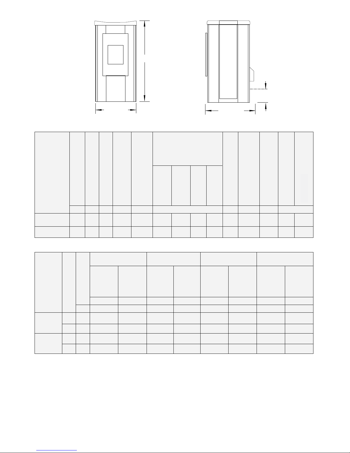
1138mm
584mm
685mm
flue
188mm
Technical Data:
* The type-tested output range is taken from the original test certificates and may deviate slightly from the specified values.
Model / Type
Output range*
Fuel capacity
Boiler water content
Water, resistance at Δ10K
Boiler / air flow rate
Boiler dimensions
Boiler weight
Flue tube diameter
(external)
Minimum draught required
Flow and return
Emptying
Height
Height of flue
tube
Width
Depth
KW kg l mbar % mm kg mm Pa inches
EVO AQUA 9
2.710
35 20 13.2 87:13 1138 188 584 685 265 100 5 ¾ ½
EVO AQUA 15
4.5-
14.9
35 20 33.1 90:10 1138 188 584 685 265 100 5 ¾ ½
Emissions:
Type
Output range
Efficiency
Dust Carbon monoxide CO Organic carbon OGC Nitrogen oxides NOx
referred to
the rel.
energy
referred to
the O2
content of
referred to
the rel.
energy
referred to
the O2
content of
referred to
the rel.
energy
referred to
the O2
content of
referred to
the rel.
energy
referred to
the O2
content of
13% 13% 13% 13%
% mg/MJ mg/m³ mg/MJ mg/m³ mg/MJ mg/m³ mg/MJ mg/m³
EVO 9
NL 92.8 11 17 29 46 <2 2 66 105
TL 94.6 10 16 96 152 3 4 58 92
EVO 15
NL 94 8 13 26 40 2 3 74 113
TL 95.4 17 26 82 126 <2 <2 64 99
Test Type:
The EVO AQUA has been tested by the Technische Universität Wien (Technical University of Vienna) according
to EN 14785. The stove complies with the emission requirements according to Art. 15a B-VG concerning safety
precautions and efficiency. The original test certificates are held by the manufacturer.
Mains Voltage / Power Supply
The appliance is designed to operate with an electrical supply of 230 VAC/50 Hz. Voltage fluctuations from
-15% to +10% are acceptable.
Dimensions
Thermal discharge
© EUROHEAT DISTRIBUTORS (H.B.S) LTD. July 2011
Instructions Part Number IN1231 Ed 1
6
9
8
7
6
5
4
3
2
1
2
15
14
13
12
11
10
7
6
5
4
1
2
3
8
9
10
11
15
14
13
12
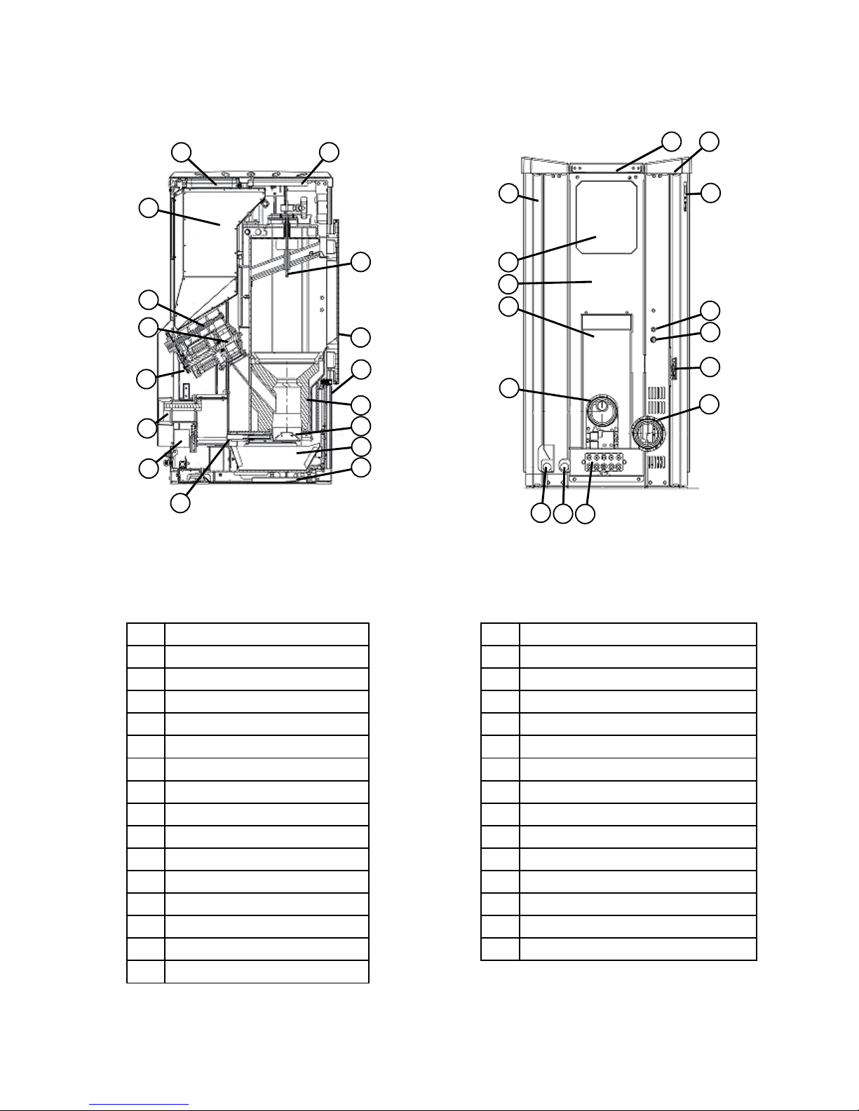
Evo Components
Sectional Drawing Through Evo Aqvo Rear View of Evo Aqua
1 Pellet hopper lid
2 Front cover flame
3 Temperature sensor
4 Firebox door
5 Ash pan door
6 Refactory brick
7 Comb grate
8 Ash pan
9 Base plate
10 Comb grate motor
11 External air connection
12 Ignition element
13 Screw conveyor motor
14 Rotary valve
15 Screw conveyer
16 Pellet hopper
1 Pellet hopper lid
2 Top cover plate
3 Control panel
4 Fuse
5 STB safety cut out
6 Data connection socket
7 Flue outlet from stove
8 Flow connection with safety valve
9 Return connection
10 Access to fit cables
11 Connection for combustion air
12 Cover for screw conveyor motor
13 Rear panel
14 Vacuum filling cover (optional)
15 Side panel

© EUROHEAT DISTRIBUTORS (H.B.S) LTD. July 2011
Instructions Part Number IN1231 Ed 1
7
Important Information Prior to Installation and Commissioning
Carefully read through this information prior to installation and commissioning of the
stove.
SPECIALIST INSTALLATION AND COMMISSIONING:
Correct operation of the boiler/installation can only be achieved if installation is carried out by a trained
specialist (licensed installer or qualified heating engineer) according to all the relevant standards and legal
requirements. Initial commissioning can be carried out as required by a suitably trained and qualified heating
engineer. Prior to initial commissioning of the boiler by a specialist, the operator of the system must ensure
the system is ready for operation (i.e. electrical cabling, hydraulic connections, unobstructed and suitable flue,
suitable heat dissipation and appropriate fuel).
CORRECT OPERATION:
Please note that all heating equipment is potentially dangerous and that no heating equipment is childproof. It
must therefore not be operated by children or other unauthorised and untrained personnel. Training is given by
your specialist installer, authorised customer services or SHT customer services technician, when commissioning
or during servicing. In the event of unprofessional installation, commissioning, or incorrect operation involving
non-observance of the device-specific instructions, as given in the technical documentation accompanying this
product all warranties are void and no guarantee claims will be accepted. A system for ensuring the boiler
return flow temperature is maintained above 55°C and the use of a buffer cylinder are essential for correct
operation, as is hydraulic balancing of the system. The system heated by the boiler must allow the device to
run for a minimum time of 1.5 – 2 hours per combustion cycle with the boiler at a minimum of 50% of its rated
output.
FUEL AND SET-UP:
The stove must be operated by a competent operator using only the appropriate fuel, as specified in these
instructions, and in suitable, dry boiler rooms/installation locations. The fuel store must also be dry and meet
the fuel-specific requirements. The boiler room/installation room and fuel store must comply with the relevant
construction and safety regulations. The storage room must only be entered after prior ventilation and when
the stove has been switched off and disconnected from the power supply.
FLUE REQUIREMENTS FOR STOVES:
The stove requires a flue system that has been installed by a HETAS approved installer. Adequate provision must
be made for cleaning access.
PERIODIC CLEANING AND SERVICING OF THE INSTALLATION:
Each heating installation of this stove, including all associated system components must be serviced and
cleaned periodically to ensure correct functioning and efficient operation. Observe the cleaning and servicing
requirements in these instructions. Only a clean and correctly adjusted boiler is an efficient boiler. A coating of
only 1 mm of dust on the heat exchanger surfaces increases fuel consumption by approximately 7%.
THE CORRECT ASSEMBLY SEQUENCE:
Observe the correct assembly sequence given in these instructions. The insulating jacket, sheet-metal cladding
including insulation, must be fitted before the water is connected. Before commissioning fill the stove with the
heat transfer medium in accordance with the relevant standards and ensure a suitable operating pressure is
generated in the manifold lines.
OBSERVE ALL REGULATIONS AND SAFETY INSTRUCTIONS:
Ensure that you comply with all the requirements of the relevant laws, standards, building regulations and all
related safety requirements for heating systems, boiler rooms and fuel storage rooms. Further information can
be obtained from your competent installation company and building authority.

© EUROHEAT DISTRIBUTORS (H.B.S) LTD. July 2011
Instructions Part Number IN1231 Ed 1
8
1 System Requirements
The products of SHT Heiztechnik aus Salzburg GmbH are designed to work in combination with other components
of a heating system and to provide trouble free performance. The entire system should be designed to ensure
all components are compatible with each other and for the fulfilment of your heating requirements. For this
reason we recommend the system is designed by a qualified heating engineer who will be able to calculate
your heating load and be able to estimate reliably your expected fuel consumption.
Experience shows that a heating system is operated at rated load for a total of approximately 1500 hours
during a heating season. This is the total rated load and partial load hours added together. In this instance an
EVO 9 operating at 10kW for 1500 hrs. will produce 15000 kWh per year and burning pellets with a calorific
value of 4.8kWh/kg the annual consumption of pellets will be 15000 divided by 4.8 giving 3125kg.
1.1 Calculation of Heat Requirements
Choosing the right size of boiler to suit the specified heat requirements and the operating conditions is paramount
to ensuring satisfactory operation of the stove. For the stove to operate efficiently the boiler needs to be able
to produce heat at a minimum of 50% of its rated output for an operating time of between 1.5 to 2 hours or
higher at each burning cycle to ensure all tars and soot that may have been developed when the stove was
reaching its full operating temperature have been burned off.
The stove will need to dissipate aproximately 10% to 15% of its output to room and the remaining 85% to 90%
to be sent to the hydralic circuits. The heat generated in the boiler must be able to be discharged to the outside.
This is achieved to a lesser extent (approximately 10 to 15%) via the glass in the door and the outer shell of the
boiler. Most of the heat (85% to 90%) is transferred to the hot water circuit which is connected to the heating
system. Make sure that the system as a whole is also able to dissipate the amount of heat produced.
The heat requirements can only be calculated by taking the entire system into account. The system designer
is usually responsible for this task. Note that the boiler, connected to a buffer cylinder, must have a minimum
operating time of 1.5 to 2 hours running at least 50% of its rated output. This ensures the burner has time to
clear any tars and soot that may have been produced when the combustion chamber was below its normal
operating temperature and so maintain optimum efficiency.
1.2 Application Possibilities
As a main heating system: Operating as a central heating appliance in a low-energy requirement home.
As an additional heating system: Operating as an addition to other heat sources.
This distinction is important when designing the system especially when selecting components such as a buffer
cylinder or contemplating an additional thermal solar heating system.
Note: Domestic Water Heating in Summer Operation
The EVO AQUA is designed to give the majority of its heat output to its boiler and a minimum heating output
to the room of installation. At 9 kW the ratio is approximately 87% to boiler and 13% to room and at 15kW it
is 90% to boiler and 10% to room. However, as the output to room cannot be avoided entirely if it is to supply
domestic water heating during the summer months, undesirable room heating may occur. If this heating is
not required, we would recommend the addition of an alternative domestic water heating system such as an
electric immersion heater or a thermal solar heating system. Your heating engineer will be able to give you
suitable options.
© EUROHEAT DISTRIBUTORS (H.B.S) LTD. July 2011
Instructions Part Number IN1231 Ed 1
9
It should be remembered that if additional heating sources, such as solar thermal systems, are incorporated
into your heating system, it may be possible to provide domestic hot water and space heating without the EVO
AQUA running during periods of mild weather. For this reason we always recommend a radiator is fitted in the
room in which the stove is installed.
1.3 Water System, Output Consumption
Heating requirements and hot water storage facilities must provide for the appliance to operate for 1.5 to 2
hours for at least 50% of its rated output per combustion cycle. The minimum accumulator sizing, assuming the
input of no other heating devices is as follows:
Evo Aqua 9kW 400 litres
Evo Aqua 15kW 500 litres
2. Combustion Air Supply
Due to advances in energy-saving technology for residential buildings, building shells are becoming increasingly
sealed off from the atmosphere. If combustion air for a stove is taken from inside this shell a suitably sized
permanent air vent must be provided. Operating open flue stoves in combination with other extraction
ventilation systems is only permitted under specific conditions. Rika/SHT pellet boilers need approximately 25
and 30 m³/h and any other system drawing air from the house shell such as kitchen extraction fans should be
taken into account; this is must be born in mind if such systems are installed at, or after, the original ventilation
requirements were calculated.
a) An adequate supply of combustion air is essential and if the stove is sourcing this air from the room in which
it is installed adequate ventilation must be provided. Please see the relevant technical information given in our
assembly instructions when other ventilation systems, such as extractor hoods, may affect the air availability.
b) It is possible to fit an external combustion air supply to EVO AQUA when installing it or at a later date if
additional appliances that may affect the stove’s air supply are fitted. This will allow all combustion air to be
drawn from outside the dwelling.
Fresh Air Kit: RKA1026
If using a fresh air kit where a draught
stabiliser has been fitted to the
starter pipe, free air must be supplied
in accordance with current Building
Regulations.
© EUROHEAT DISTRIBUTORS (H.B.S) LTD. July 2011
Instructions Part Number IN1231 Ed 1
10
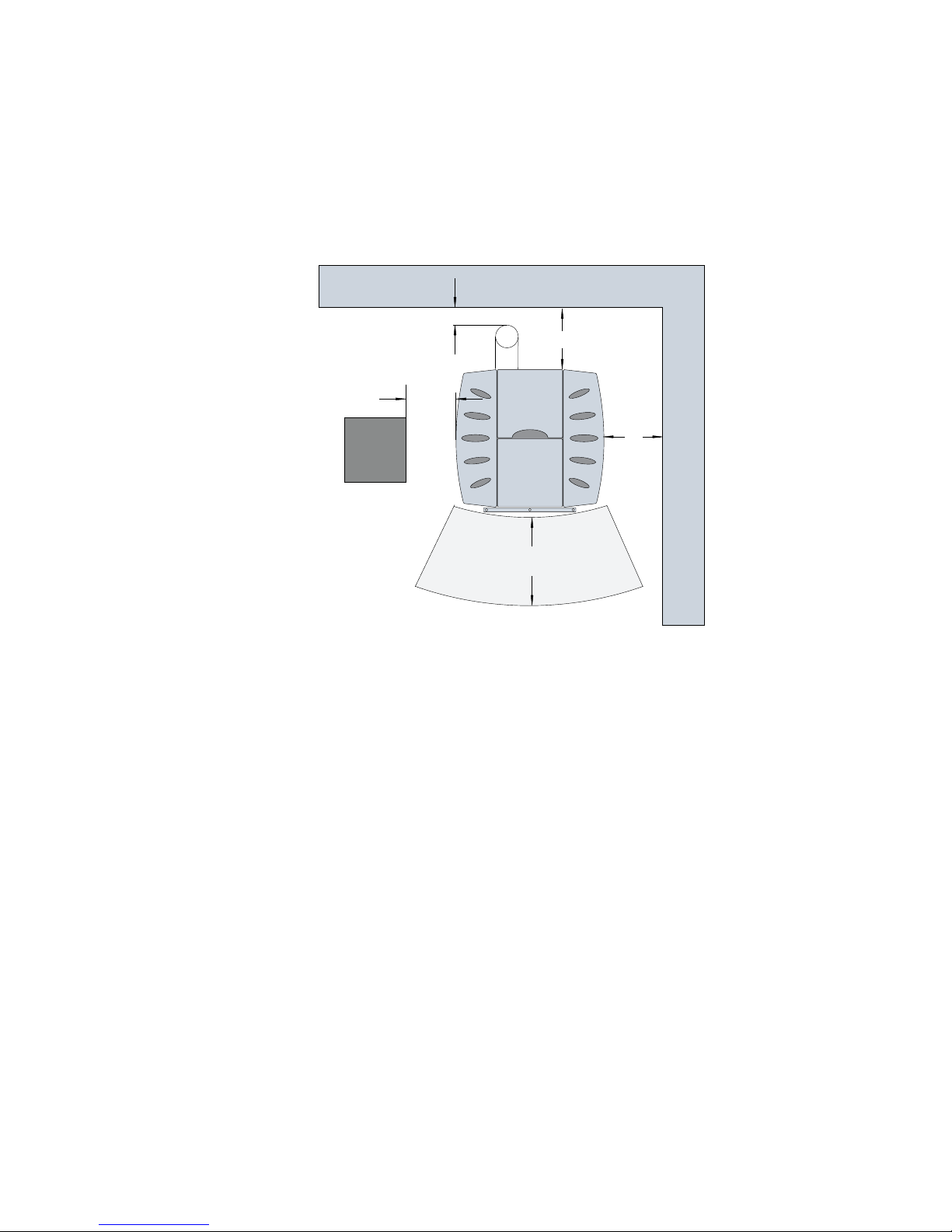
EVO installed in a living room
Distance A:
At least 80 cm in the radiation zone must be considered as an area where people and objects are not allowed
when the stove is operating.
Distance B:
A minimum distance of 40 cm should be maintained from movable objects such as chairs or tables.
Distance C:
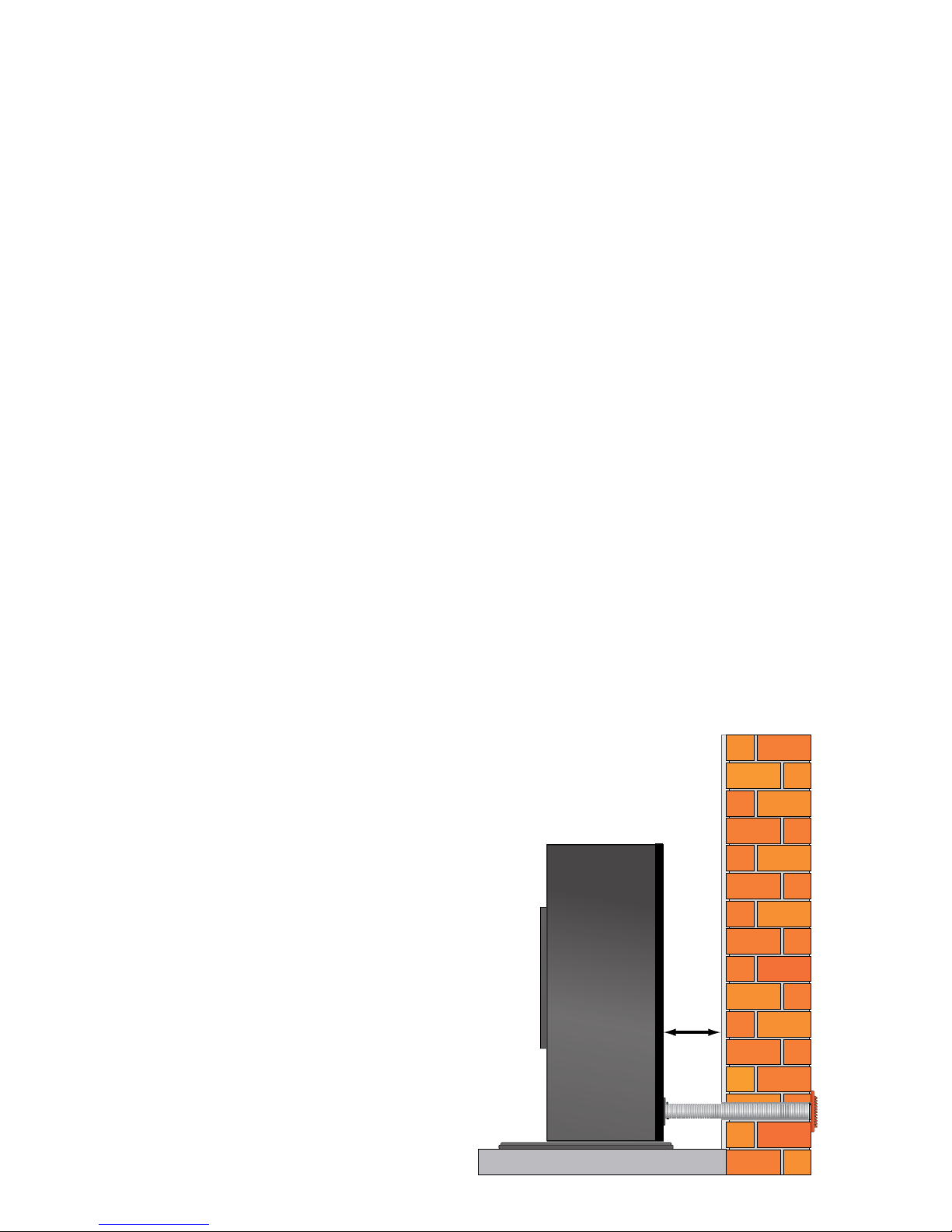
At least 10 cm between the flue tube and the wall if it is not inserted directly in the rear wall.
Distance D:
At least 50 cm from immovable objects on the right and left sides to allow for servicing and maintenance.
Distance E:
Minimum distance between boiler and rear wall in the installation room providing that distance C is observed,
or the flue tube is inserted directly in the rear wall.
E = 20 cm distance from rear wall if the boiler is installed without automatic conveying system.
E = 20 cm distance if installed with the automatic conveying system, visionconvey AIR, if the hoses are passed
straight down into the floor or are routed to the side in the same room.
E = 35 cm distance if installed with the automatic conveying system, visionconvey AIR, if the hoses are routed
in the rear wall behind the boiler.
3 Sighting of the Stove
3.1 Minimum Distances from Flammable Materials
These distances are our recommended minimum distances but the fire safety requirements of applicable
standards must be observed when constructing the system as a whole.
All flammable materials in the immediate vicinity of the boiler must be protected from the effects of heat.
C
D
A
B
E
 Loading...