

Page 1

Page 2

Eurogard Service-Server: Manual
by Falk Schönfeld
Copyright © 2011-2014 Eurogard GmbH
Page 3

iii
Table of Contents
1. System description .................................................................................................... 1
Short overview ................................................................................................... 1
Function overview and concept ............................................................................ 1
Preconditions ..................................................................................................... 3
2. Installation and operation ............................................................................................ 4
Hardware installation ............................................................................................. 4
Connection and control elements on the rear side of the device .............................. 4
Connections on the front panel ........................................................................ 4
Initial contact set-up .............................................................................................. 5
Operating concept ................................................................................................. 5
Installation – quick set up guide .............................................................................. 6
Preparation of the ServiceServer ...................................................................... 7
Connection to the Internet .............................................................................. 8
Time ........................................................................................................... 8
Certificates .................................................................................................. 9
Next steps ................................................................................................... 9
OpenVPN .................................................................................................... 9
3. Configuration options of the ServiceServer ................................................................... 10
Administration area ............................................................................................. 11
Basic settings/LAN .............................................................................................. 12
Host name ................................................................................................. 12
Domain name ............................................................................................. 12
IP-Address of the Server in the LAN network .................................................. 12
Netmask .................................................................................................... 13
DHCP-Server for the LAN ............................................................................ 13
DHCP area ................................................................................................. 13
HTTPS-Port of the web interface ................................................................... 13
Web access/WAN ............................................................................................... 13
WAN-Media ............................................................................................... 13
Configuration of connection .......................................................................... 14
Time ................................................................................................................. 14
Time source ............................................................................................... 15
Time zone .................................................................................................. 15
Device is NTP-Server .................................................................................. 15
NTP-Update interval .................................................................................... 15
NTP-Server chart ........................................................................................ 15
dDNS ................................................................................................................ 15
Certificates ......................................................................................................... 16
Field contents ............................................................................................. 17
Validity in days .......................................................................................... 18
Issue certificates for WAN IP as well ............................................................. 18
Issue certificates for LAN IP as well .............................................................. 19
Generate Server certificates ........................................................................... 19
Import root certificate .................................................................................. 19
Show Server certificate ................................................................................ 27
OpenVPN .......................................................................................................... 27
OpenVPN-Mode ......................................................................................... 28
Logging of client connections in a database ..................................................... 28
DHCP range for VPN-clients of the admin network ........................................... 28
Start port ................................................................................................... 28
Enable client-to-client connections ................................................................. 28
Limit VPN packet size ................................................................................. 28
Keeping a log file ....................................................................................... 29
Detail options of the logs ............................................................................. 29
Maximum size of the logs ............................................................................ 29
Page 4

Eurogard Service-Server
iv
Allow access to the admin network to VPN-Clients ........................................... 29
Time interval for keep-alive-packets in seconds ................................................ 29
VPN restart after how many unsuccessful Pings ................................................ 30
Cryptoalgorithm .......................................................................................... 30
Service networks ................................................................................................. 30
General overview ....................................................................................... 31
Update network status .................................................................................. 31
Restart all networks ..................................................................................... 31
Add network .............................................................................................. 31
Change service networks .............................................................................. 31
Delete service networks ................................................................................ 32
Accounts ............................................................................................................ 32
Refresh status ............................................................................................. 32
Add new account ........................................................................................ 32
New user certificate ..................................................................................... 33
Download .................................................................................................. 33
Change password ........................................................................................ 34
Delete account ............................................................................................ 34
Logs ................................................................................................................. 34
Firewall ............................................................................................................. 34
Port 22 - ssh .............................................................................................. 34
Port 443 - https ........................................................................................... 34
Allow LAN devices access via external interface .............................................. 35
Allow access service network/LAN ................................................................ 35
4. Messaging .............................................................................................................. 36
Email ................................................................................................................ 36
Emailing .................................................................................................... 36
Email address ............................................................................................. 36
Server/Port ................................................................................................. 36
Username/Password ..................................................................................... 36
Transport encryption .................................................................................... 36
Allow certificates of unknown origin .............................................................. 36
Email account for receiving .......................................................................... 36
Test configuration ....................................................................................... 36
Reports .............................................................................................................. 37
5. Status and diagnosis ................................................................................................. 38
Connections ........................................................................................................ 38
DHCP ............................................................................................................... 38
OpenVPN .......................................................................................................... 38
Logs ................................................................................................................. 38
Firewall ............................................................................................................. 39
dDNS ................................................................................................................ 39
Diagnosis ........................................................................................................... 39
6. Backup-Maintenance ................................................................................................ 41
Backup .............................................................................................................. 41
Restore point .............................................................................................. 41
Upload restore point .................................................................................... 41
Reset ......................................................................................................... 41
Service .............................................................................................................. 41
Maintenance access ..................................................................................... 41
7. Logging of connection data ....................................................................................... 43
General .............................................................................................................. 43
Show logged connection data ................................................................................ 43
Read out log database .......................................................................................... 43
8. Disclaimer .............................................................................................................. 45
General .............................................................................................................. 45
Safety instructions ............................................................................................... 45
Proper use, installation and assembly ...................................................................... 45
Page 5

Eurogard Service-Server
v
A. Wichtige Begriffe ................................................................................................... 46
Page 6

vi
List of Figures
1.1. Eurogard ServiceServer ............................................................................................ 1
1.2. VPN-concept of the Remoteserviceproducts ................................................................. 2
Page 7

vii
List of Examples
3.1. Host- and Domain name ......................................................................................... 12
3.2. URL for HTTPS in case of different port .................................................................. 13
7.1. Syntax URL VPN-Log ........................................................................................... 43
7.2. Example of valid query .......................................................................................... 44
Page 8

1
Kapitel 1. System description
Short overview
The Eurogard ServiceServer system is a product from the Eurogard remote service family. These
products represent a secure, central access to remote, IP-capable terminal devices via Internet, with
the focus always on automation and control engineering.
Abbildung 1.1. Eurogard ServiceServer
The ServiceServer system connects the user PC and the machine, plant or computer network via a
secure connection, a so-called “virtual private network”, VPN in short.
During this process, the communication between the participants is secured through the encryption
protocol SSL. This guarantees confidentiality and integrity of all exchanged data.
The device includes a complete VPN system with certificate and user administration in order to provide
the user with an optimally secured programming and monitoring access to the machine network.
The protected web administration area can be accessed via HTTPS or VPN and provides the
administrator with all necessary tools for the integration of devices and machine networks and for the
administration of programmers and service staff.
Function overview and concept
The key element of the Eurogard remote service solution is the Eurogard ServiceServer which provides
an especially protected dial-up service for network connections.
Connection is established via software which can be installed on any standard PC.
Since devices in the area of control and automation engineering do not provide possibilities for a VPN
connection or for software installation as standard, the Eurogard ServiceRouter serves as a bridging
device.
The controls of the plants to be monitored are connected to the ServiceRouter. Just as with the
service technicians’ or programmers’ PCs, the ServiceRouter then establishes a connection to the
ServiceServer.
All devices, even though connected via different Internet connections, perform as if in a common
LAN. The only indication for the spatial separation between the network participants may be the higher
latency rates.
With the help of a ServiceRouter, the ServiceServer sets up a separate, independent VPN for each
plant network.
In this context, it is necessary to ensure that the different plant networks each use different IP ranges.
The ServiceRouter which integrates the plant network into the VPN can choose between Ethernet,
UMTS, PPPoE (DSL) or WLAN for the Internet connection.
Page 9
System description
2
The security architecture provides for two main user groups: administrators and users associated with
a plant network. As a basic principle, administrators have access to all networks und administrative
functions of the ServiceServer; plant network users can only access the allocated plant network.
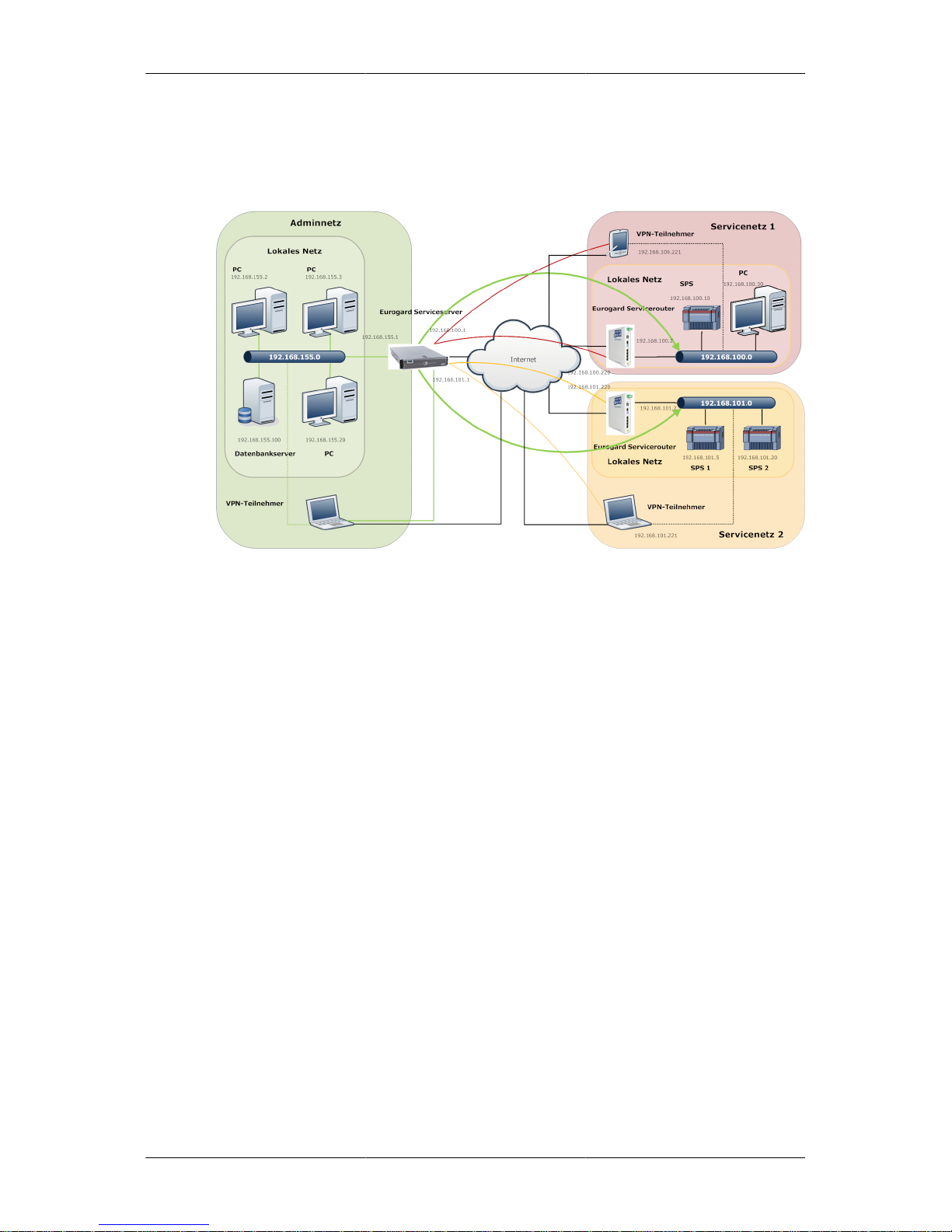
Abbildung 1.2. VPN-concept of the Remoteserviceproducts
Eurogard offers a free and efficient OpenVPN client which administers your certificates, logs access
times to various plants and securely sets up connections to the routers at the plant via a mouse click.
The Eurogard ServiceServer and router provide a complete solution for the remote access to IP-based
automation structures in machines and plants.
As the ServiceRouter, the ServiceServer has two network sides at its disposal.
• WAN-side
Used to connect the device to the Internet. Here, access to plant networks or to the LAN side is
only possible indirectly via VPN.
• LAN-side
This is the primary “working network”. Here, all units and PC’s have direct access to all plant
networks and their devices.
All data packets from LAN devices sent to the Internet via the Server are masked via Source-NAT by
the Server. As a consequence, only the external Server IP is outwardly visible, in case the device goes
online indirectly on the WAN-side via the in-house network. This helps to keep down the installation
and administration efforts and expenses.
A so-called service network is installed on the ServiceServer for each plant for which a remote
service is to be set up. This is shown on the right hand side of Abbildung 1.2, „VPN-concept of the
Remoteserviceproducts“. In order to allow for admin network access to each single network at the
same time, a unique network IP-address has to be assigned to each of these networks.
The next step is to create an account for an Eurogard ServiceRouter on the Server. A configuration
file is downloaded from the Server into the Router. This Router is parameterised and integrated into
the plant network. It acts as intermediary between the various devices of the plant and the service
network of the ServiceServer. All IP terminals of the plant can now be accessed via the LAN network
at the Server.
Page 10

System description
3
In the process of generating a new VPN access its range of validity needs to be specified. This range
may be a specifically selected service network or the entire network, in the case of an administrative
account.
In the standard configuration of the Server, devices from a service network are not able to send or
receive data to or from other service networks. Devices from the plant network can also not access
devices in the admin network. Only the admin network is authorised to communicate with terminal
devices in machine networks. This is symbolised on the left hand side of Abbildung 1.2, „VPN-concept
of the Remoteserviceproducts“. All functions shown may be configured separately. Accessibility
within the plant network, either between local or between VPN clients, is not affected and always
ensured.
Preconditions
Prerequisite for an adequate operation of the Eurogard ServiceServer is a sufficiently dimensioned
Internet connection. This will depend on your specific requirements. Depending on the hardware, the
Server can handle bandwidths of a minimum of 100 MBit to 1 GBit.
The Server must have a DNS entry available. This is an essential precondition for the overall concept
to function “out-of- the-box”, even if operation via IP is possible. By means of this entry, the clients
are able to ‘find’ and access the Server.
It may often make sense to attribute a static IP to the ServiceServer in order to guarantee 24-hour
accessibility to the service network. Dynamic IPs may result in “Blackouts” of up to 15 minutes.
In those cases where the Eurogard remote service concept may be required to be used with a dynamic
Internet IP, our devices support the dynamic DNS services of DynDNS [http://www.dyndns.com].
Since the ServiceServer deals with client’s requests from the Internet, the accessibility of the relevant
ports has to be guaranteed. In the case of an NAT-Firewall protecting the device, this means that port
forwarding has to be set up.
Please note the preconditions regarding the operation of the ServiceRouter which are required for
setting up a plant network.
Page 11

4
Chapter 2. Installation and operation
Hardware installation
The device is designed for installation in a 19“-Rack and requires 1 HE; a mounting depth of 60 cm
will be adequate.
Connection and control elements on the rear side of
the device
On the rear side of the device, the mains power supply, the reset button and an LED signalling errors
and specific operating conditions can be found.
Reset button
For a reset, press the reset button for at least 3 seconds, then release to start the reset process. This
is shown by fast flashing of the Error LED. After a few seconds, the device restarts twice. After
approximately one minute, the device is back in default status.
The reset function is available 15 seconds after power up of the Server, indicated by the one second
interval flashing of the Error LED.
Error-LED
The Error-LED indicates errors and operating status messages.
After set up of the device, the Server requires approximately 15 seconds in order to initialise the
hardware and the operating system.
Subsequently, the LED starts flashing at one second intervals and the Router starts setting up its
configuration.
When this process is terminated, the LED switches off and the Server is in operating mode; should
this not be the case, an error has occurred during installation of the stored configuration.
If a reset is triggered or a restore point is loaded, the LED flashes rapidly for a short period of time
and the device will restart. After re-initialisation, the Server carries out a new configuration which is
also indicated by fast flashing of the LED. Subsequently, the system is restarted again.
Connections on the front panel
Three RJ-45 network connections can be found at the front.
WAN-connector socket
Connect the “WAN” socket to a web-enabled network or DSL connection. Any network traffic via
the Internet has to pass via this connector.
LAN-connector sockets
The “LAN1” and “LAN2” sockets are bridged internally and have switch functionality. All terminal
devices connected to the Server via LAN1/2 can set up a direct connection to all devices in all service
networks.
Page 12

Installation and operation
5
Communication between devices connected via LAN and devices connected via WAN is not
supported.
USB-connectors
At present, both USB-connectors are deactivated. When required, functionality may be supplied for
customer-specific extensions or future software releases.
Initial contact set-up
The Server should be installed under suitable environmental conditions. Further information can be
found in the separate instruction booklet included.
Start the device and wait for approximately 2 minutes to reach the state of operational readiness.
At initial start of the device or after a reset, the following parameters are set:
• WAN → Ethernet and address assignment via DHCP
• LAN → IP: 192.168.155.1 and address allocation via DHCP
• Admin account/-password: Eurogard/Eurogard
All interactions with the ServiceServer are carried out via a web interface. In order to access the web
interface, the LAN-IP of the Server has to be accessible via your PC. In the simplest case, just connect
the LAN interface of the Server and your PC by means of a switch or directly via cross-over patch
cable. If not previously carried out, configure your PC for address assignment via DHCP.
Calling up http://192.168.155.1 in your browser will show the web interface of the Server.
If an error message is displayed, check the network setting of your computer and – if set – deactivate
the use of a proxy server via your browser.
Operating concept
Since the Eurogard ServiceServer is a network component, the entire interaction with the user is carried
out via a web frontend in the browser. Operation using a monitor, keyboard and mouse is not supported.
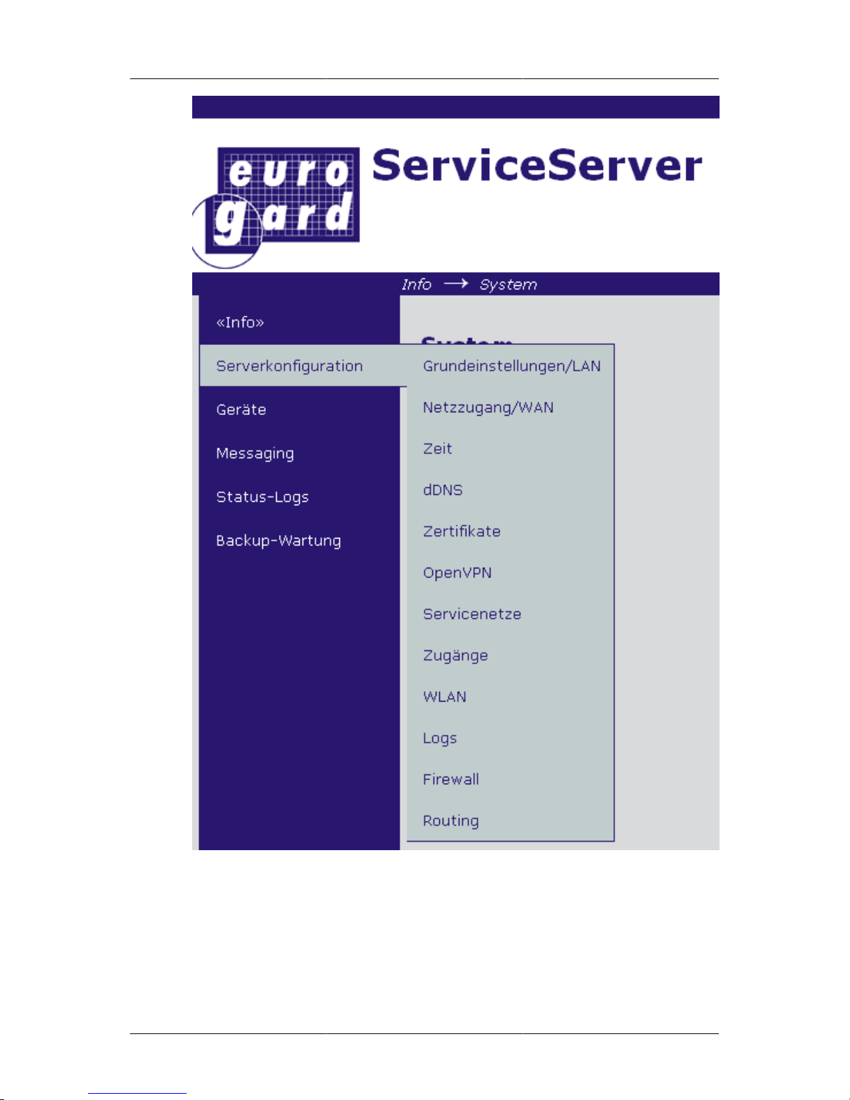
The user interface has a main menu and, depending on the menu item chosen, a corresponding submenu.
The main menu is on the left-hand side of the screen. Move the cursor to one of the menu items to
open the corresponding sub-menus.
Page 13

Installation and operation
6
On the right hand side there is an overview and the option for log-in as administrator on the
ServiceServer.
Some of the menu items only display information, some allow for changing the settings. Menu items
allowing changes to settings, often have a “Save” button in the lower left corner. Only after pressing
the “Save” button will entered data be submitted. Some of the tables apply direct changes and the
"save" button need not be pressed. Additionally, some events require confirmation after a safety query.
This manual can also be found in the device in browser form. The help link in the submenu bar connects
to the relevant chapter of this context-sensitive manual. In this process, the browser opens a new
window or a new tab. Where no help pages are displayed after clicking the help link, please check
to see if a new tab has appeared in the background or if you have received notification from a popup
blocker.
Installation – quick set up guide
This chapter guides you through the configuration. Only the basic operational parameters are set here.
For a more detailed and exhaustive explanation of all menu items, please see Chapter 3 Chapter 3,
Configuration options of the ServiceServer.
Call up the web interface of the ServiceServer. Proceed according to the instructions in paragraph the
section called “Initial contact set-up ”.
Before proceeding, log on to the Server as Admin. Please click the link “Adminlogin” in the upper
right hand corner to do so.
Page 14

Installation and operation
7
Enter Eurogard both as user name and password.
After successful login the Login-Link changes to the Logout-Link, stating the name of the current
user, in this case "Eurogard".
You are now logged in as administrator on the Eurogard ServiceServer.
Go through the various subsections in sequence.
Preparation of the ServiceServer
Open the main menu item "Server configuration" and the submenu item "Basic settings/LAN".
Settings which should be altered in all cases are the host and domain names. These names will reappear
in the certificates which have to be generated as one of the next steps as well as in the configuration
files for the clients.
On the LAN side the Server has been set to the IP 192.168.155.1. If there is any reason to change this,
please do so under menu item IP address in LAN network.
Where the LAN-IP has been changed, and after pressing the “Save” button, the Server can be accessed
via its new IP. Please adjust the network settings of your PC accordingly.
If your computer is configured for address allocation via DHCP, briefly disconnect the network cable
or make the following entry at the command prompt:
ipconfig /renew
our computer should receive a new IP from the Server and display a similar text:
Microsoft Windows [Version 6.1.7600]
Copyright (c) 2009 Microsoft Corporation. Alle Rechte vorbehalten.
C:\Users\klaus>ipconfig /renew
Windows-IP-Konfiguration
Page 15

Installation and operation
8
Es kann kein Vorgang auf LAN-Verbindung 2 ausgeführt werden, solange dessen Medium nichtverbunden ist.
Ethernet-Adapter LAN-Verbindung 2:
Medienstatus. . . . . . . . . . . : Medium getrennt
Verbindungsspezifisches DNS-Suffix:
Ethernet-Adapter LAN-Verbindung:
Verbindungsspezifisches DNS-Suffix: example.com
Verbindungslokale IPv6-Adresse . : fe80::cd46:3019:dbd7:c9f1
IPv4-Adresse . . . . . . . . . . : 192.168.155.100
Subnetzmaske . . . . . . . . . . : 255.255.255.0
Standardgateway . . . . . . . . . : 192.168.155.1
Adjust the entry in the address bar of your browser to the newly configured IP of the Server
Please contact your company’s IT-administrator before assigning a valid host and domain name to the
device. In case there is no sufficient infrastructure, for example due to the size of your business, your
Internet provider may be able to supply you with the relevant names.
If your company’s Internet connection has a daily changing IP, the free service for dynamic DNS of
DynDNS [http://www.dyndns.com] will be your best choice.
Alternatively, please contact our support hotline for assistance in making the most suitable choice.
Connection to the Internet
You can set your preferred access to the Internet under the menu item “Server configuration”
→
“Network access/WAN”. You can choose between Ethernet via DHCP or static IP, as well as PPPoE
(DSL).
Select your way of access and test the functionality. Go to Status-Logs → Diagnosis. You should be
able to ping an Internet host such as, for example, google.com. This is precondition for the following
installation steps.
Try restarting if the device is unable to access the Internet in spite of correct settings. This can be done
under Backup-Maintenance → Service.
In accordance with the standard settings, the UDP ports from 1195 onwards have to be reachable via
Internet, so that the Server can be accessed by the VPN-Clients. The number of consecutive ports
depends on the number of service networks to be used. This, on the other hand, is specified by the
Server hardware in use. Set up port-forwarding, if required, Portweiterleitung and/or configure your
firewall correspondingly.
Time
For safe and stable VPN operation between Eurogard ServiceServer and Client-PCs or ServiceRouters,
all subscribers require a synchronised time base.
As standard, the Server synchronises the correct time via Internet per NTP NTP.
The correct time zone for Germany is pre-set.
The correct time of the Server can be viewed in the upper right-hand corner, below the Adminlogin
link. The time displayed is the time of the website access, not the current time.
If the clock has not been set, the time indicated flashes red.
Page 16

Installation and operation
9
Certificates
As previously stated, all VPN clients require a certificate. The contents of the certificate are determined
by particular specifications. In order to keep the operation of the Server as simple as possible, most
entries are set automatically. Only very few remain to be set by you.
Since a certificate is a kind of digital passport, it should include “personal” data of the owner.
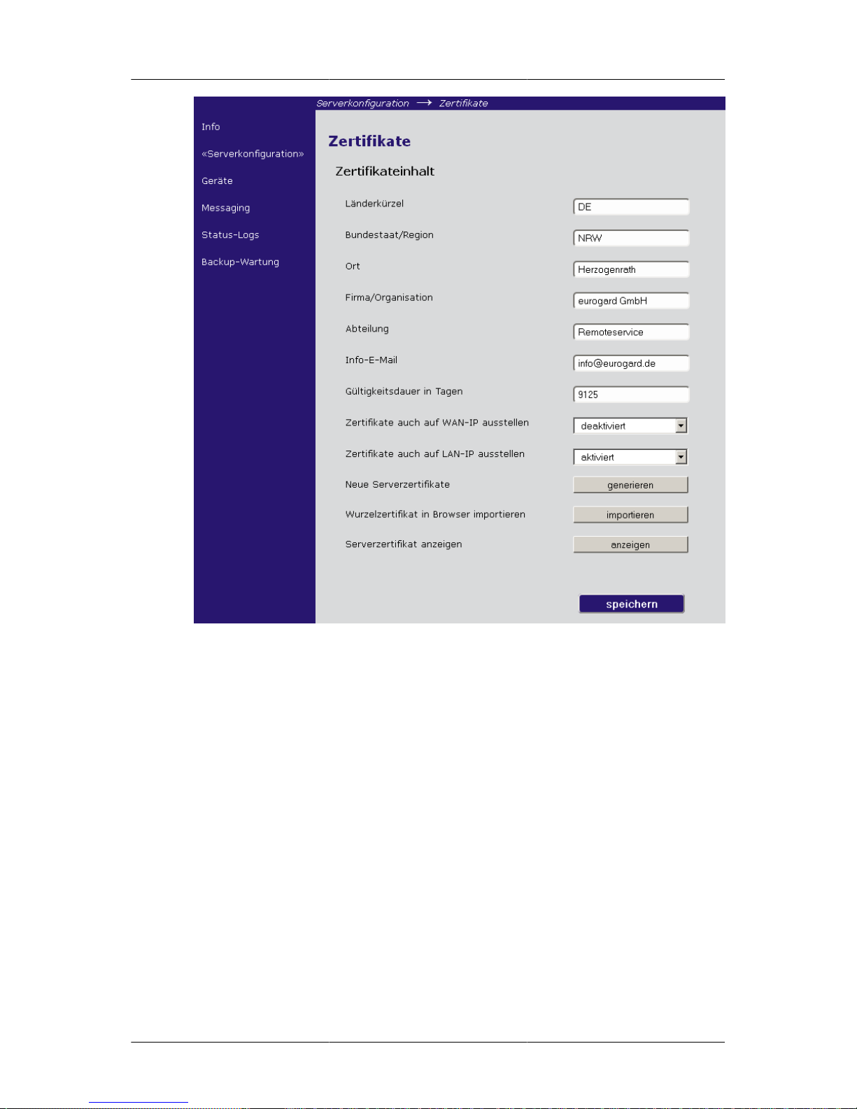
Call up Server configuration → Certificates.
Enter the relevant data for your company. The pre-entered data in the text fields serves as example.
Enter your Internet country code (ISO 3166-2), for example DE for Germany or AT for Austria.
Confirm your settings by pressing the button "save" in the bottom right corner of your screen.
Caution
After expiry of the validity period, access to the VPN network with the expired certificate
is no longer possible. Set up a reminder in due time in order to create and use new
certificates.
Initiate the generation of the certificates for the ServiceServer by clicking "generate new server
certificates". Since this utilises random values, the duration of this process may vary from time to
time. Please be patient as this may take several minutes.
Next steps
Your ServiceServer is ready for operation. Under menu item Server configuration → Web access und
Server configuration → Accounts you can now set up a service network and/or a VPN client account.
OpenVPN
Call up the menu item Server configuration → OpenVPN. Set the select field to "on" and press"save".
When this process is completed, the Server is ready for operation.
Page 17

10
Chapter 3. Configuration options of
the ServiceServer
This chapter describes in detail the configuration of the Server. In order to quickly put the Server into
operational state, as sufficient for most applications, please refer to the chapter „Installation – Quick
guide“ the section called “Installation – quick set up guide ”.
The structure of this chapter follows the main menu of the Server configuration.
Page 18
Configuration options
of the ServiceServer
11
The following chapter describes all configuration options for all sub menus.
Administration area
In order to change the configuration or the operating parameters of the ServiceServer it is necessary
to login to your admin account on the Server. Click the Adminlogin in the upper right-hand corner.
Page 19

Configuration options
of the ServiceServer
12
For the initial start-up or reconfiguration after a Reset, please us username/password Eurogard.
After successful Login, the Login link changes to Logout link.
Basic settings/LAN
Under this menu item you set the basic operating parameters.
Host name
The host name is the network name of the Server. It may only consist of letters, numbers and the minus
sign. This name will be included in the Server certificates and helps the VPN subscribers locate the
device in the Internet.
Default: servicerouter
Domain name
Computers are grouped into administrative units via domains.
For domain names, the same rules apply as for host names, additionally however, the full stop "."may
be used which helps with regards the structure.
Please enter the complete domain of which your Server is part of at this point. Also the domain name
is included in the certificates and helps to locate the device in the net.
Example 3.1. Host- and Domain name
Assuming you have registered with DynDNS.com under the name mein-server.dyndns.org , this
means mein-server is host name and dyndns.org is domain name.
Default: example.com
IP-Address of the Server in the LAN network
In the case where the Server’s IP address in the LAN has to be changed, this can be carried out at
this point.
IP addresses are a clear identification of computers and networks. Please make sure not to double
assign them.
IP addresses consist of a network and a host part. Any network the ServiceServer may have to access
also has to be explicitly specified.
Default: 192.168.155.1
Page 20

Configuration options
of the ServiceServer
13
Netmask
Enter the netmask for the LAN interface at this point.
Default: 255.255.255.0
DHCP-Server for the LAN
Network settings can be dynamically assigned to network subscribers by means of DHCP
If this option is activated, the hosts’ requests via the LAN interface, the network parameter IP address,
DNS Server and Standard gateway are transmitted.
Default: activated
DHCP area
The pool of available IPs can be configured. This means an address range can be created from which
subscribers can use fixed IPs without the danger of overlapping with addresses assigned dynamically
via DHCP.
Please note that the VPN-Software also assigns addresses to the clients via DHCP. There must be no
overlapping of the settings specified at this point and the DHCP area for the admin network under
OpenVPN. For further information please refer to “DHCP-area for VPN clients of the admin network”
the section called “DHCP range for VPN-clients of the admin network ”.
Default: 192.168.155.100 - 192.168.155.120
HTTPS-Port of the web interface
In this field, the port can be entered where the integrated webserver software receives SSL-encrypted
connections. The ServiceServer issues its configuration websites via this Software. Since these pages,
depending on the configuration, are also available via the Internet, this is carried out with SSLencryption. The relevant protocol is HTTPS instead of HTTP.
Caution
Please enter URLs in der form https://192.168.155.1 in your browser.
The default port for HTTPS is 443. If you wish to change this port, you must also inform your browser.
Add a colon, followed by the port number between server address and directory path.
Example 3.2. URL for HTTPS in case of different port
If your new HTTPS-Port is, for example, 4444, the URL has to be entered as follows:
https://serviceserver.example.com:4444/cgi-bin/webif/admin/system.sh bzw.
https://192.168.155.1:4444/cgi-bin/webif/admin/system.sh
Default: 443
Web access/WAN
This section describes the allocation of the Internet connection for the ServiceServer.
WAN-Media
Please select the type of connection at this point. You can choose between Ethernet and DSL per
PPPoE.
Page 21

Configuration options
of the ServiceServer
14
Configuration of connection
Select the configuration of the Internet connection of the Server. You can choose between DHCP and
manual specification of network parameters.
Please note that for DSL access, at this point in time, the Server only supports automatic configuration
via DHCP.
Ethernet - static
The input screen holds all necessary parameters. Specification of the default gateway is supported
only for the entry of an IP.
DSL - DHCP
Enter username and password as determined by your ISP. Press "save" and the ServiceServer sets up
the connection and will keep it permanently. If the connection is terminated, the device tries to restore
it. No manual interaction or intervention is required.
MTU
This value should only be altered if your device is running behind a NAT cascade and Path MTU
Discovery by means of filtering of ICMP-Typ-3-Code-4 packets does not work.
Default: 1500
Time
For a successful VPN operation between Eurogard ServiceServer and Client-PCs or ServiceRouter, a
synchronous time base for all subscribers is required. As a standard, the Server gets the correct time
via Internet per NTP NTP. The correct time zone for Germany is pre-set.
If NTP is to be used in connection with public time servers, ensure that the Server can access the
Internet on Port 123/UDP.
The time set on the device can be checked in the upper right-hand corner of the menu screen, below
the link to the Admin-Login.
If the battery-backed real-time clock has been reset, the display of date and time in the upper righthand corner flashes in red.
Page 22

Configuration options
of the ServiceServer
15
All changed settings, also in the table must be saved by clicking the "save" button in the bottom righthand corner.
Time source
Here you can select if the device is to receive its time settings via the network protocol NTP or if it
is to be set manually.
Please note that without regular adjustment the current device time starts to diverge.
Default: NTP
Time zone
Adjust the time zone of the device. This will allow the device to define the time difference to the
Greenwich meridian and to correct the NTP time. This will also automatically change summer and
winter time.
Default: Central Europe
Device is NTP-Server
If the device is to communicate the current time to requesting network subscribers, this menu item
should be enabled.
Default: enabled
NTP-Update interval
This configures the interval of time levelling via NTP.
Default: daily
NTP-Server chart
This chart lists the servers and ports to be used for time levelling via NTP NTP. These settings may
be changed if required, for example in order to only use already existing company servers.
dDNS
In order for the ServiceServer to be traceable by its VPN clients in the case of an Internet connection
with changing IP addresses, a provider is required who changes the reference of host-/domain names
to your IP as soon as your Internet IP changes. At this point, the Eurogard remote service products
only support the DynDNS [http://www.dyndns.com]. In the basic version, which is sufficient for most
purposes, this service is free of charge.
Caution
This service is only required if you are connected to the Internet via a regularly changing
IP address. This applies for example in the case of basic DSL connections.
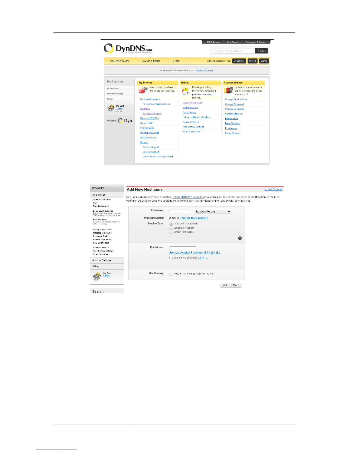
In order to access this service, enter http://www.dyndns.com. Create an account and log in.
Now click "Add Host Services".
Page 23
Configuration options
of the ServiceServer
16
Choose a host name and select a domain from the list.
Exit the provider’s website after configuration of the account and the host name; set the parameters
for the ServiceServer.
Enter the account information on the dDNS site and the host name and domain name on the System
Settings site
From now on, the Server checks every ten minutes to see if your Internet IP has changed. If this is the
case, it is updated by the DynDNS.com server.
You can check the exact point in time of the last update and the current IP address under Status-Logs
→
dDNS. For further information please refer to the section called “dDNS”.
Certificates
Certificates play a major role in the security concept of the Eurogard ServiceServer.
Page 24

Configuration options
of the ServiceServer
17
The Server itself, every service network and every VPN access have their own key and the relevant
certificate. The keys ensure security of communication, the certificates establish the reference between
the keys and their owners. This makes a certificate a digital passport.
In this manual, the term ‘certificate’ is always meant as including the relevant key.
Each of these certificates has a field name “Common name”. This shows the owner of the certificate.
This may be a server, as for example “serviceserver.Eurogard.de" or also “Klaus Meyer”.
Certificates are organised in chains. This means a trustworthy party issues the first certificate, the
so-called root-certificate. This is exclusively intended to sign further certificates. The next signed
certificated can itself then sign new certificates.
This means that if the issuer and his allocation procedures are trustworthy I can also trust the owner
of a certificate signed by this root certificate.
In practice, companies have established themselves over the past years which professionally
authenticate certificates for their customers in accordance with strict criteria. Most applications
working with certificates, such as for example browsers, have lists of trustworthy issuers.
If, for example, a browser does not know the signatory of the certificate of a SSL-encrypted website,
it will issue a warning message.
Since a self-created root certificate is used in the ServiceServer which is therefore unknown to the
browser, a warning message is issued when the web configuration site is called up per HTTPS “Import
root certificate to browser” the section called “Import root certificate ” describes how to inform the
browser about your root certificates and thus avoid warning messages.
Caution
Ensure that your certificates don’t fall into the wrong hands! Whoever is in possession
of your Server certificates can issue client certificates!
As a standard, certificates have a limited validity. Please ensure that the Server has the correct current
time before generating new certificates.
This is essential for the whole system to function. The host or domain name in use must not be changed
after generation of the certificates.
Field contents
The contents of these fields are displayed in the certificates. This is not mandatory regarding security
and functionality but helps to specify and distinguish the different certificates.
Enter the required information. The country code consists of two letters and corresponds 1to the
website code, for example DE, AT, NL. All other entries have a maximum length of 64 characters.
1
gemäß ISO 3166-2
Page 25
Configuration options
of the ServiceServer
18
Validity in days
Enter the validity period of the Server certificates in days. Choose a sufficiently long period. If the
validity expires, clients will be unable to connect to your device, even with valid certificates.
Default: 9125
This corresponds to 25 years.
Issue certificates for WAN IP as well
If this is activated, the certificate is bound not only to the host name but also to the IP of the WAN
interface. This IP is read directly from the interface during the certificate generation process.
When calling up the web surface per HTTS via the IP, for example https://10.1.1.1 no browser warning
is issued in the case of an imported root certificate (see the section called “Import root certificate ”).
In case of a subsequently changed WAN IP the general availability of the web interface remains
unaffected and further ensured.
This option is only practical if the WAN IP does not change.
Voreinstellung: disabled
Page 26

Configuration options
of the ServiceServer
19
Issue certificates for LAN IP as well
As in the section called “Issue certificates for WAN IP as well ” ”, the certificate can also be tied to
the LAN IP.
Default: enabled
Generate Server certificates
Caution
Before generating certificates, ensure that the device has the correct current time and that
the host and the domain names correspond with the ones for future operation.
The server certificate consists of a root certificate for issuing further certificates and a server certificate
used by applications such as OpenVPN or the webserver software. The Server certificate is the digital
passport of the Server. If these certificates are re-generated, all other certificates including the ones
of the VPN subscribers lose their validity.
If the web interface of the Server is accessed via HTTPS, for example https://
servicerouter.example.com, the browser compares the address called up to the one in the Server
certificate. In order to avoid error messages with regards the certificate, host names and domain names
should already be configured accordingly in the menu “Server configuration” → “Basic settings/LAN”.
In case these options are selected, this also applies to the WAN and LAN IP.
Caution
If there are clients "in action" while re-generating the server certificates, these clients
will no longer be able to connect unless new certificates are loaded to the clients or the
old server certificates are restored.
Press the button generate in order to generate new server certificates. Since random values are created
here, the length of this process may vary on occasion. The new certificates are available after a few
minutes.
If the certificates are created in the during VPN processes, these processes are terminated. Go to the
configuration site Server configuration -> OpenVPN in order to re-activate VPN functionality.
Import root certificate
In order to avoid browser alarm messages regarding the certificate, the root certificate can be imported
by the browser. In order to do so, click the button "import".
From now on there will be no further warning messages when accessing the web interface.
The next paragraph describes importing and deleting of the root certificate using Internet Explorers
8 a Mozilla Firefox 3.6.
Internet Explorer 8
Import of the root certificate
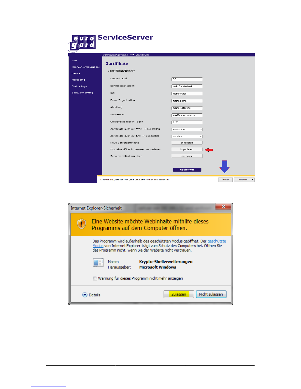
Clicking import opens a dialog box as in the following picture:
Page 27
Configuration options
of the ServiceServer
20
Click Open and Import in the next dialog.
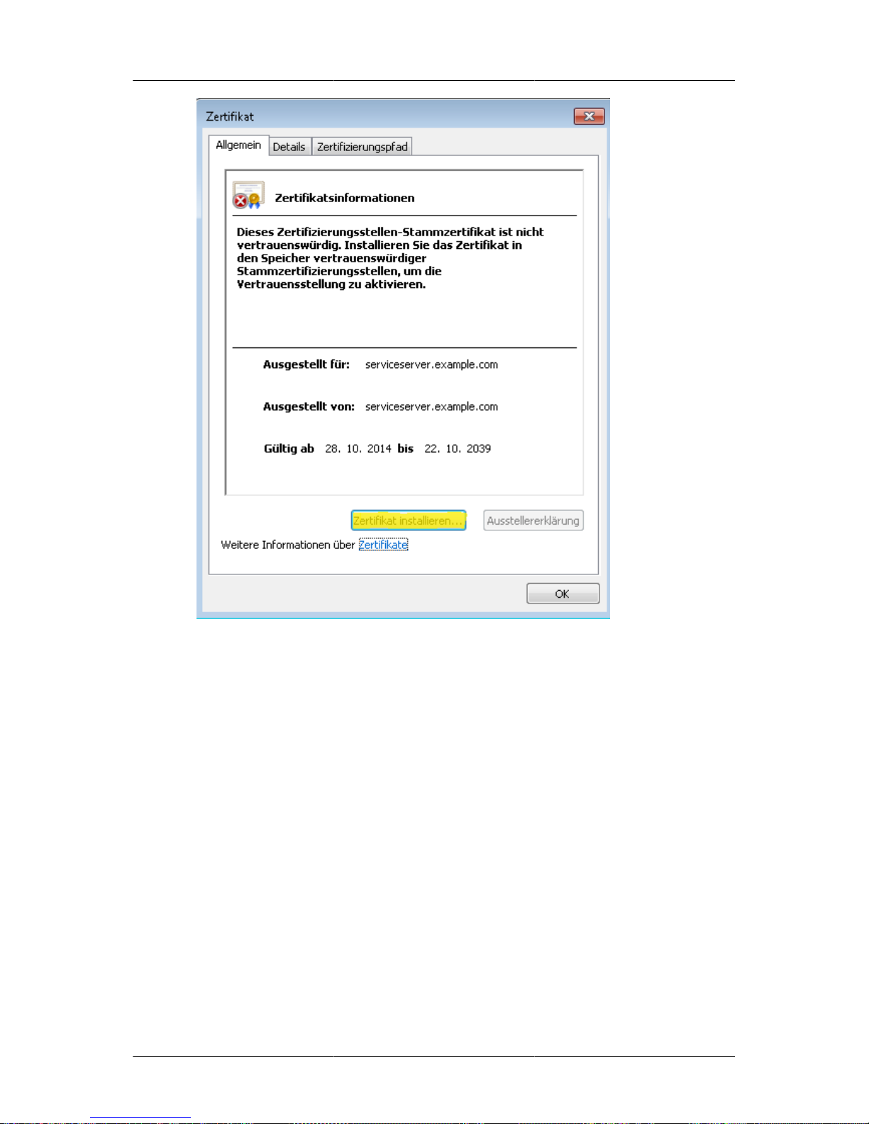
The certificate window is displayed and the certificate can be installed on the PC by clicking the button
Install certificate.
Page 28
Configuration options
of the ServiceServer
21
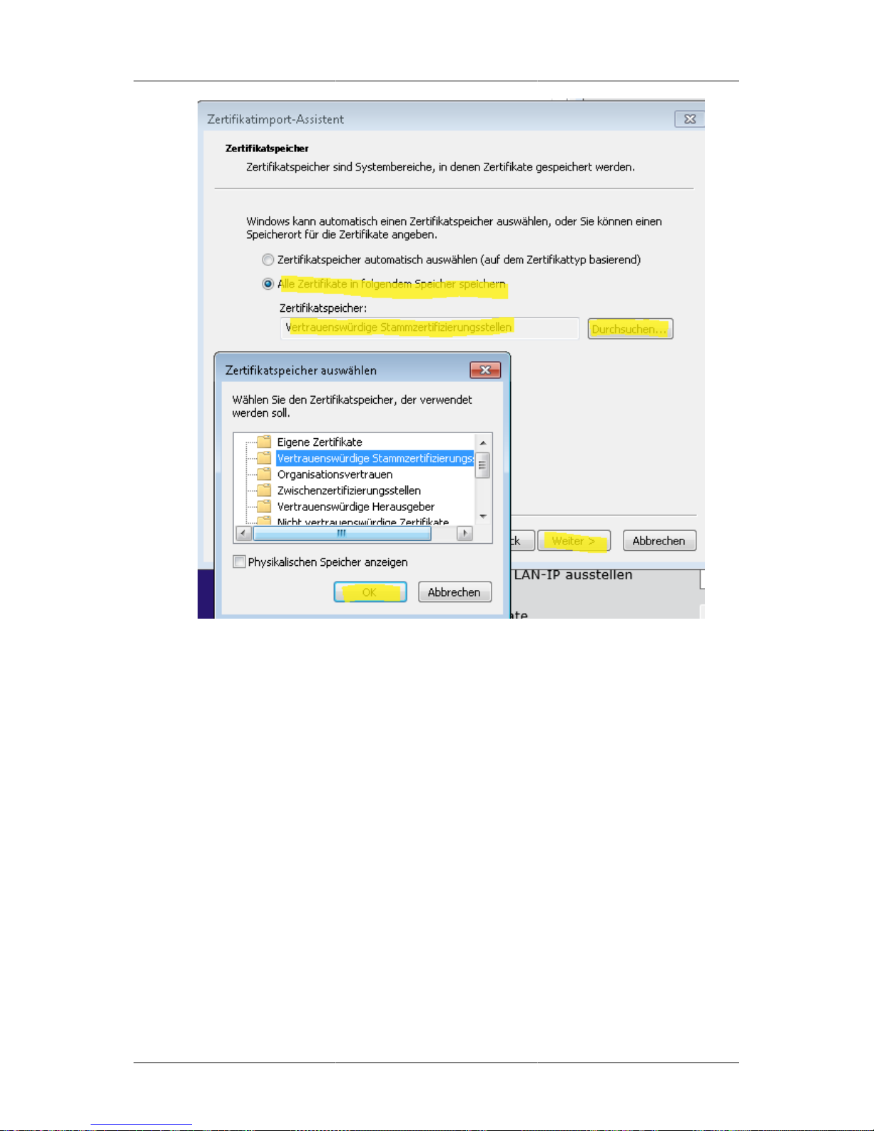
The certificate import wizard is started. Click Next. The next dialog specifies the storage location.
Click Browse in order to select a location manually.
From the list displayed select Trusted Root Certification Authorities.
Page 29
Configuration options
of the ServiceServer
22
Confirm the two following safety warnings and the certificate is installed.
Remove the root certificate
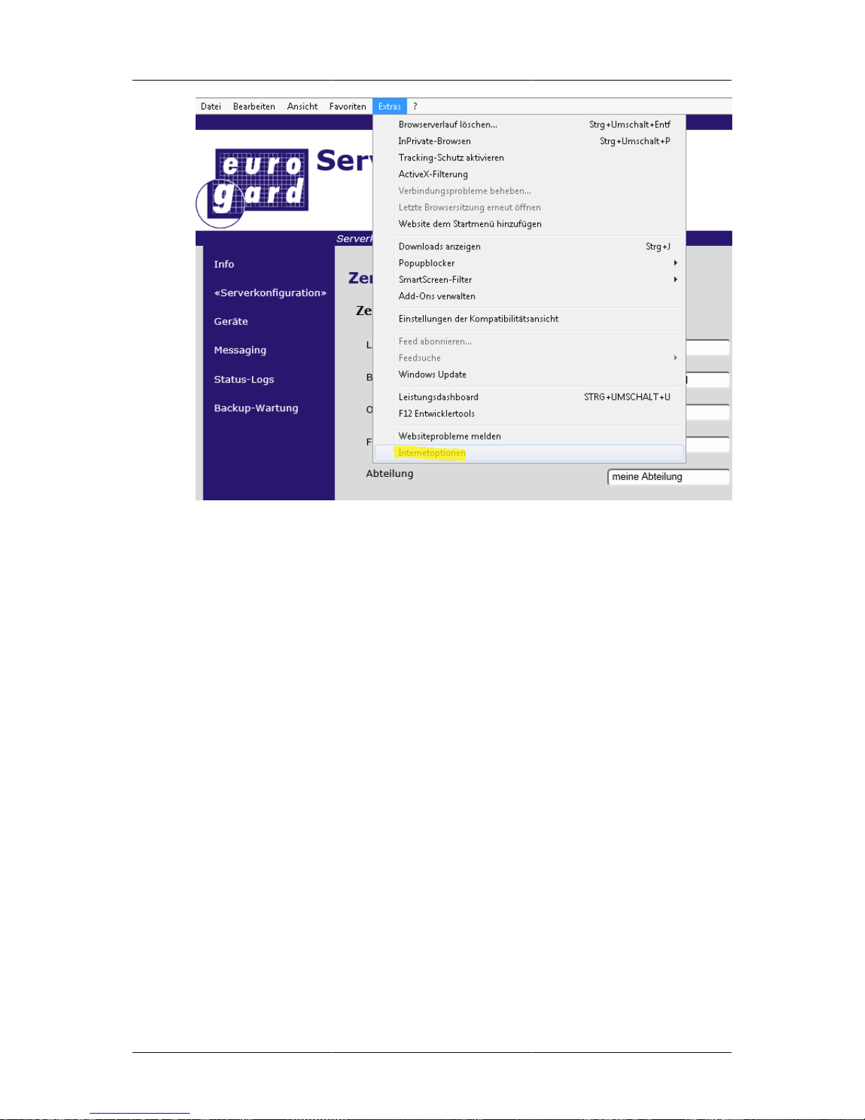
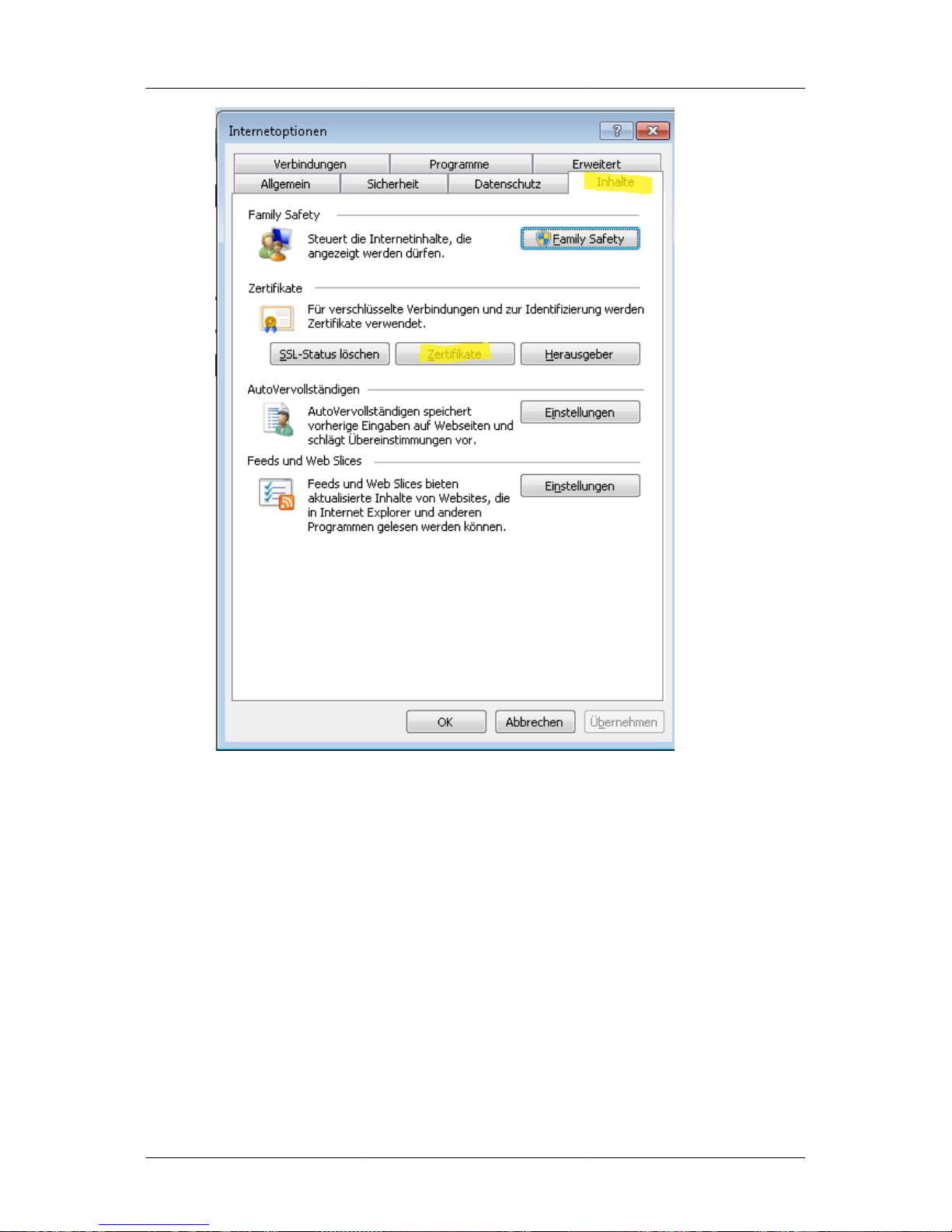
Click the menu item Extras in the upper right-hand corner of the browser and select Internet options.
Page 30
Configuration options
of the ServiceServer
23
Click the tab Contents and then Certifikates.
Page 31
Configuration options
of the ServiceServer
24
The tab Trusted Root Certification Authorities displays the relevant list. Select your certificate
authority and click delete.
Confirm the safety instructions and the certificate is removed from the computer.
Mozilla Firefox 5.0
Import of the root certificate
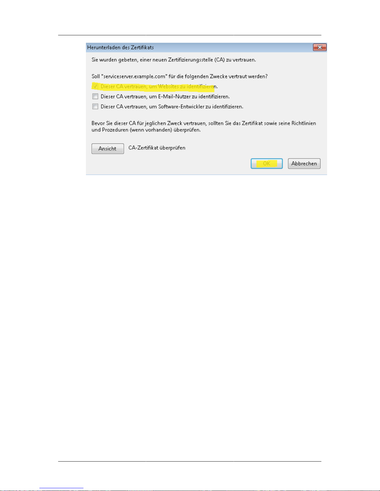
After clicking the button import a selection screen is displayed. Choose the first option according to
the following screen and confirm by pressing OK.
Page 32
Configuration options
of the ServiceServer
25
Use of the certificate is configured for Firefox.
Remove the root certificate
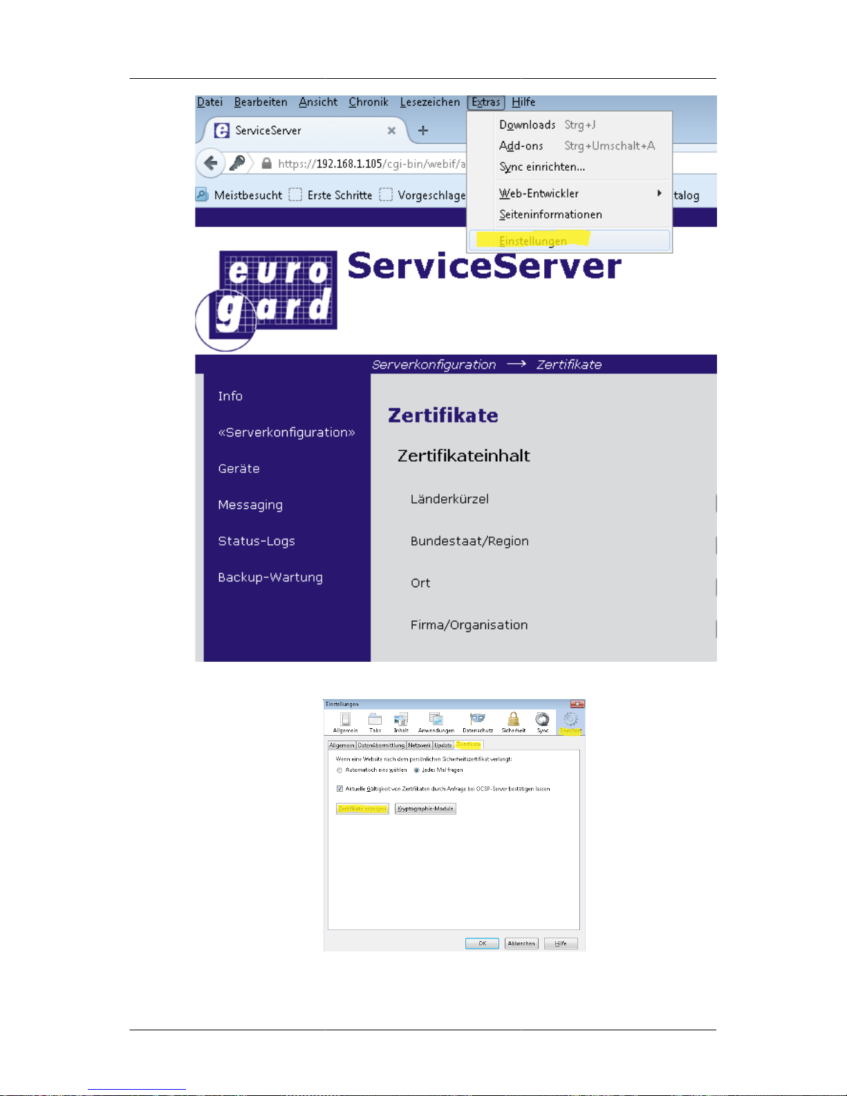
Select the menu item Settings from Extras.
Page 33
Configuration options
of the ServiceServer
26
Go to the tab Advances and Encryption then click the button Show certificates.
Page 34
Configuration options
of the ServiceServer
27
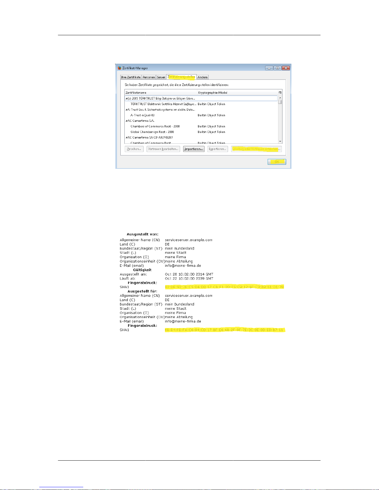
The relevant menu item will display the certification bodies; select your certificate. Please note
that Firefox displays the list sorted by the field "Company/Organisation". Remove the certificate by
pressing delete
Confirm the safety warning and the certificate is deleted.
Show Server certificate
This menu item shows the list of server certificates. The most important safety feature is the fingerprint
displayed. It is the check sum of the keys used in the certificate.
Any number of certificates with identical field contents can be generated, the fingerprints, however,
will always be different making this an important security feature.
OpenVPN
Parameters for the VPN operation can be set in this menu. Since a separate OpenVPN process is started
for each service network, only some pre-settings are determined here. Some settings can be selected
individually for the various processes. This will be indicated in the relevant cases.
Valid certificates are required in order to be able to activate OpenVPN. If this does not apply, a warning
message is displayed when opening the configuration site.
Page 35

Configuration options
of the ServiceServer
28
Caution
If settings are changed and saved here during VPN operation, this will result in a reset of
all VPN networks. All connected clients will consequently be disconnected and cannot
be accessed for approximately 2 minutes.
OpenVPN-Mode
OpenVPN can be activated or de-activated here. If this option is greyed out and not accessible it means
that no valid certificates are available.
Since no valid certificates can be found on the device.
Default: off
Logging of client connections in a database
With this option, VPN connections are logged in an SQL database. For further information see chapter
Chapter 7, Logging of connection data .
Default: on
DHCP range for VPN-clients of the admin network
Since the OpenVPN software in the Server allocated an IP to each client and since IP can never be
double-allocated the IP range must be customised in accordance with requirements.
Please note that the Server also allocates IP addresses via the LAN. The areas from which addresses are
assigned must not overlap since this will inevitably result in breakdowns and inaccessibility of clients.
Default: from 192.168.155.200 to 192.168.155.220
Start port
Every service network is assigned to its own software process which means that each of these networks
requires a port on the Server.
The parameter "Startport" indicates the first of the ports to be used. If not de-activated this port is
normally assigned to the admin network.
Ports are assigned to new service networks in continuous order whereas "Blanks" originating from
deletion processes of data are re-assigned as priority.
Direct intervention regarding the ports associated with the service network is not provided for.
Default: 1195
Enable client-to-client connections
This option controls intercommunication of the VPN clients within one service network.
Default: on
Limit VPN packet size
Since the packet size of 1500 Bytes must not be exceeded in the IP networks used in this context, the
size of the packets sent through the tunnel can be limited. This is carried out entirely transparently
through the VPN application and undetected by the rest of the software.
Page 36

Configuration options
of the ServiceServer
29
Since the Eurogard ServiceServer and router mask all data per NAT NAT prior to the forwarding to
the WAN interface and since the devices, in some cases, are operated behind NAT NAT Gateways,
packets will exceed the maximum size. It therefore has to be limited.
If the value chosen value is too low, it will affect the throughput, if chosen too high, the connection will
“freeze”. The best compromise between throughput and general accessibility results in the following:
Default: 1400
Keeping a log file
If the Open VPN processes are to keep a log file, this has to be specified at this point. The logs record
logins and logouts, depending on the level of detail, and display the negotiated connection parameters.
Log files may be downloaded under Status-Logs #Logs.
Default: on
Detail options of the logs
The higher the level, the more detailed the logs. Step 1 logs every connection set up and termination.
Step 2 additionally displays information about the certificates in use, the encryption and HMAC
algorithm.
Finally, in Step 5, among other functions, each packet sent and received is marked with a ‘w’ or ‘r’.
Default: 1
Maximum size of the logs
In this drop-down box the maximum size for a log file of each single VPN process is specified. If this
value is exceeded, the log is saved and a new empty log file is set up
Default: 512 Kilobyte
Allow access to the admin network to VPN-Clients
If this function is enabled, the devices of the VPN clients (PSs, Eurogard ServiceRouter …. ) are
automatically configured on the network side in such a way that the Server LAN (Admin network)
can be accessed from their service network.
This is useful if, for example, there are central logs or monitoring devices in the admin network which
have to be accessed by controls or PCs from the Service networks.
Caution
This option is only required if a device from the service network actively sets up
the connection to the LAN. If a device from the LAN wants to access a device in a
service network, however, this is permanently enabled and this function is not required.
Depending on your network structure this function can represent a safety risk.
When this function is activated, a corresponding firewall rule is automatically set.
Default: off
Time interval for keep-alive-packets in seconds
The VPN software uses the connectionless UDP protocol for data transport, therefore neither the
Server nor the client can directly check if the VPN tunnel is still available. For this reason a test
datagram is sent in predefined intervals.
Page 37
Configuration options
of the ServiceServer
30
These intervals can be defined here. If n replies (to be configured in the next section) fail to appear,
the connection is reset.
During the dial-in of the clients, these settings are also transferred to the clients and implemented. This
is of particular importance if the Server is connected to the Internet via a dynamic IP.
Also the display of the connected VPN clients uses this value. If a ServiceRouter is disconnected from
the power supply it is shown as connected until the time out for the next Ping has expired.
Default: 60 Seconds
VPN restart after how many unsuccessful Pings
This configures how many test datagrams have to remain unanswered before the connection is reestablished. Since UDP is connectionless it is not unusual that a packet is “lost” on the way. This
applies particularly to wireless connections depending on signal strength like eg. UMTS.
Default: 2
This option is also transmitted to the clients during connection set up. .
Cryptoalgorithm
Since the Router Version 1 uses a different cryptographic algorithm from Version 2, the Router
generation in use is specified here.
If you intend to use a V1 ServiceRouter in your plants please choose option Compatibility mode V1Router.
Default: Standard v2-Router
Service networks
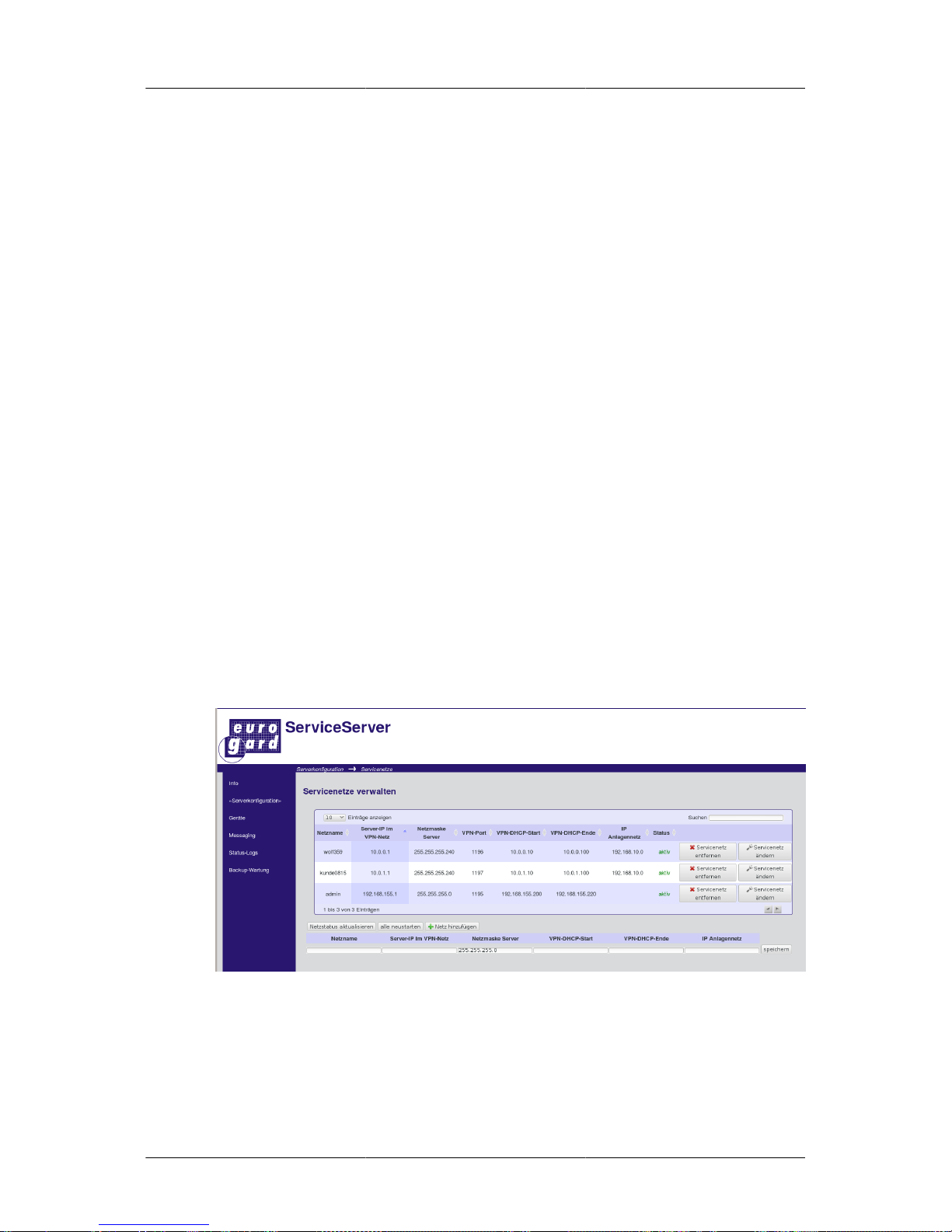
This site serves the administration of service networks and, at the same time, gives an overview of the
operating parameters of the various networks.
All configured networks, including the admin network are shown in an overview in tabular form.
Displayed are network names, IP and network mask of the Server in this network, the port used by the
relevant VPN process, the IP pool of the VPN clients, the current status of the network at the point of
Internet request a ‘change’ button and a ‘delete’ button.
At the left hand upper corner above the table you can find a drop-down menu where the number of
lines per page is determined. You can click through the individual pages by means of the two arrows
at the bottom left of the table.
Page 38

Configuration options
of the ServiceServer
31
In the upper right corner you can find a search field which searches all fields after entering a minimum
of 2 characters, filtering for the characters entered. The search results are automatically updated with
every new entry in the search field.
General overview
IP addresses of plant networks are often determined by your customers; since they should always have
the same IP numbers, two IP ranges should be assigned for each service network. The net IP of the
plant network may be assigned more than once, the VPN network, however, has to be unique. From the
VPN side, Routers, VPN clients and Server are combined in one network. The ServiceRouter handles
the transition from the VPN network to the target network of the plant to be accessed.
Update network status
When this button is pressed, the Server checks the status of the service networks in the background.
The status column is updated network by network.
This may take several minutes, especially in the case of configurations with various networks or in the
case of low bandwidth connections between querying browser and server it may take a while because
all networks are checked, not only the ones displayed in the currently shown table.
Restart all networks
After pressing this button and confirming, all service networks are restarted, which results in a short
temporary unavailability of these networks.
The length of the interruption depends on the parameters set in the section called “Time interval for
keep-alive-packets in seconds ” and the section called “VPN restart after how many unsuccessful
Pings ”.
Add network
On pressing this button, a line is displayed below the table, where the parameters for a new network
can be entered.
Choose a network name which gives information about location or function of this network. For
technical reasons umlaut, minus signs (use underline characters instead) and leading digits are not
supported.
Enter the IP your Server is supposed to use in this network. Obviously this IP network must not yet
be in use. A class-c network mask appears which may be altered to your specifications.
Choose the IP range the Server is supposed to allocate to the VPN clients.
Please make sure that also in this IP range that no double allocations and assignments of addresses
occur between the local IP range for DHCP devices of the remote ServiceRouter or devices with static
IPs.
Save your settings; the Server generates a specific certificate for the network and you are ready to go.
After start-up it will be displayed in the chart as “active”.
If an error message is displayed, please check and, where necessary, correct your settings.
Change service networks
Next to each entry in this table is a button "change service networks". Pressing this button opens
another chart, similar to the one for adding networks.
Page 39

Configuration options
of the ServiceServer
32
The name of the network cannot be changed, the other fields contain information which can now be
edited. After pressing the button "save" on the right-hand side of the line, the new settings are applied
and the network is re-started.
The admin network does not allow changes to the server IP, since this IP follows the LAN IP
Delete service networks
After pressing this button all network users as well as the network itself are deleted after a security
confirmation prompt. The associated certificates are cancelled and are no longer usable.
Caution
If you have ‚lost‘ VPN clients in this procedure, creating a new network under the same
name will not work since the new certificate of the service network will be different
from the old one.
Only the admin network cannot be deleted at this point, please use the VPN set up site in order to
deactivate the network.
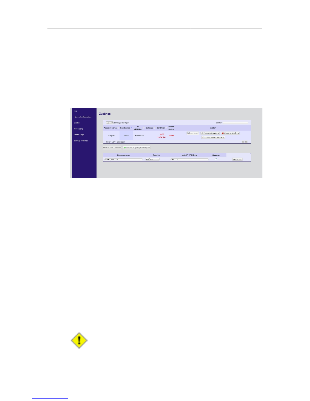
Accounts
All user accounts are administered on this site.
A warning message is displayed if the default administrator account is still active. You should create
a new account at this stage and delete the "Eurogard" account.
The existing accounts are organised in an overview chart as in the section called “Add network ”.
Again you have the possibility to filter, browse and set the maximum number of lines displayed.
The table has the following columns:
• User name (account)
• Network or group allocated to this account
• Information about certificates for this user (where available) and date and validity period of the
certificate.
• Den Onlinestatus des Nutzers. Beachten Sie auch hier wieder Online status of the user. Again, please
note the section called “Time interval for keep-alive-packets in seconds ” and the section called
“VPN restart after how many unsuccessful Pings ”. If a client does not log out of the VPN correctly,
it may take a certain length of time until his status is displayed as "offline".
• A column for activities. Here, for each user a certificate can be generated and downloaded, the
account can also be deleted.
Passwords for the various accounts can also be changed here.
Refresh status
After pressing this button, the online status of all accounts, including the ones on the current site, is
checked. The updated status is then entered into the chart.
Add new account
Pressing this button opens a new table below the overview chart where you enter the account
information.
Page 40
Configuration options
of the ServiceServer
33
Choose a name and attribute the account to a network or a group. Choose between "admin" and a new
service network. While a member of the "admin" group has rights to make administrative settings via
the web interface, members of other groups are not allowed to do so.
In contrast to an admin, a "normal" user only has access to his associated service network. This network
has to be allocated to him; choose a network from the drop-down menu when creating the account.
Obviously this network has to be configured beforehand.
In case you are creating an account for a ServiceRouter used for access to the actual plant network,
activate the “Gateway” option. Each service network requires its own gateway. The VPN network has
to have a fixed IP address since this information is required for the other VPN clients of the network.
The VPN software then configures the client routes automatically. For further information see chapter
the section called “Add network ”.
If the new user is supposed to become a member of the admin group, a password must also be allocated.
This password has to be entered when the user logs into web interface.
The password must have a minimum of 6 characters. Both the user name and the password are casesensitive. "bediener0815" and "Bediener0815" would therefore be two different accounts.
New user certificate
This triggers the generation of a new client certificate for the relevant user account. Successful
generation and validity of the certificate is displayed in a popup window as well as in the updated field
"Certificate" in the relevant line of the overview chart.
If a certificate has already been created, a security warning has to be acknowledged. In this case, the
existing certificate is revoked.
Download
Press "download" in order to download an archive file with all certificates, keys and an OpenVPN
configuration file for the relevant user.
The Eurogard Connect-Software as well as the eurogard-ServiceRouter require this for setting up the
VPN.
Depending on the validity range, this file is essential for access to the service network(s).
Caution
If this file or a storage medium containing this file is lost you should generate a new
client certificate as quickly as possible. The old certificate is automatically revoked in
this case. If a VPN-Client with this certificate is connected, his connection to the Server
will be immediately terminated.
Page 41

Configuration options
of the ServiceServer
34
If no certificates exist, the download button is deactivated and greyed out.
Change password
A new password can be created here for user access with password. After pressing this button, a field
for entering the new password is displayed below the overview table. Press the button "save" on the
right hand side in order to confirm settings.
In the case of access without password the button is deactivated and greyed out.
Delete account
By clicking this control element and confirmation upon security query the relevant account is deleted
and the certificate is revoked.
Logs
This menu provides a complete overview of all available log files; the logs for the various services
can however also be displayed in the relevant menu.
The maximum log size can be also be set here.
Firewall
The integrated firewall in the Server is part of the security concept. With a few exceptions all settings
of the firewall are automatically parameterised by the ServiceServer.
As a general rule all Eurogard remote service products mask the data traffic of the LAN clients via
NAT NAT before entering the WAN. This minimises administration requirements and enhances the
acceptance of the devices.
The following basic settings are activated as default:
• All services of the device itself and of all LAN connected devices (this includes VPN clients of the
admin network) have unlimited access to the WAN.
• Access from the WAN side, access to the device and to devices in the LAN is not possible, except
for the HTTPS secured access to the web interface of the Server to Port 443.
• All LAN and service network clients as well as VPN clients associated in these networks have
unrestricted access within their respective networks.
• As a general rule, each client in each service network can be reached from the LAN network. The
Server has no means of preventing this.
Port 22 - ssh
If the “Service access” the section called “Maintenance access ” is activated, it can be reached via
the LAN and the WAN interface. With this button, reachability of the service port via the WAN port
can be prevented.
Default: enabled if the service access has been activated beforehand
Port 443 - https
If you do not wish the web interface of the Server to be accessed from the WAN side, this option can
be blocked with this button.
Page 42

Configuration options
of the ServiceServer
35
If reachability of the HTTPS protocol has been directed to a different port from port 443, the chosen
port is opened or closed at this point.
Default: enabled
Allow LAN devices access via external interface
You can set a lock at this point if you do not wish LAN devices to access the Internet.
Default: enabled
Allow access service network/LAN
If you wish devices in service networks to access devices in the LAN, this can be enabled here. The
setting is automatically enabled, if the corresponding VPN option is enabled.
This may, for example, be necessary if a central logging or database server is running in the LAN.
In this context, please refer also to the section called “Allow access to the admin network to VPN-
Clients ”.
Default: off
Page 43

36
Chapter 4. Messaging
Under this menu item, the entire messaging to and from the Router is parameterised. Please note that
some of the options only apply to specific hardware configurations.
Email
Settings regarding sending and receiving of emails are made here. Direct email traffic through the
device is provided for in order to avoid problems of spam. For direct emailing, an email server account
must be used.
Emailing
By activating this button emails are included in the messaging process.
Email address
Enter the email address of the email account which is to be used by the Server.
Server/Port
Enter the name of the SMTP-Server and the corresponding port of your email account.
Username/Password
If authentication is required by your chosen SMTP-Server, the relevant user data can be entered here.
Transport encryption
If the SMTP server chosen supports encrypted communication, the encryption method may be chosen
at this point. Please note that, depending on the method chosen, the ports to be used may vary on one
and the same Server.
Select none if communication is to take place unencrypted. By selecting STARTTLS if available ”,
TLS transport encryption is automatically activated, in the case where this is supported by the Server.
The option SSL/TLS always tries to establish a secure connection. If this is not possible, mails will
not be delivered.
Default: STARTTLS
Allow certificates of unknown origin
If the mail server which has been configured uses self-generated certificates, this option must be
enabled; otherwise, the device will not send emails to this server.
Email account for receiving
Enter the email address of the recipient of Router messages.
Test configuration
Clicking the test button generates a status report of the device. Please note that any changes in the
configuration have to be saved before testing.
Page 44

Messaging
37
During the test, a window opens which displays the messages of the mail software and the mail server.
Reports
The device can send status reports at pre-determined intervals. This function and the intervals can be
set here.
The report includes the network parameters in use, connected VPN clients and sensor data of the
hardware such as, for example, the CPU temperature.
Page 45

38
Chapter 5. Status and diagnosis
The system status is displayed under this main menu item. No entries are made here. The structure of
the chapter follows the sub menu items.
Connections
Apart from the currently used WAN IP of the device, this provides a list of all network connections
of the Router.
The output corresponds to the one of the command line tool "netstat", called up with suppressed name
resolution.
DHCP
This site shows an overview chart of the IP addresses allocated via DHCP from the server LAN.
Only addresses allocated to local clients are displayed here. Addresses assigned via VPN cannot be
displayed here.
In detail, the table lists:
• The IP allocated to the host.
• The host name stated by the client for address allocation.
• The MAC-address of the current IP holder.
• The validity period of the assigned IP
OpenVPN
This menu item displays information about the individual OpenVPN processes pertaining to each
service network. The relevant OpenVPN connection can be chosen by pressing the select button.
The following operating data is displayed:
• Client: the account name of the client, as shown in the certificate
• Real Address: the WAN-IP of the client
• Virtual Address: the VPN-IP of the client
• received: Bytes received by the client
• sent: Bytes sent by the client
• connected: time of setting up the VPN tunnel with the ServiceServer.
Logs
Here, log files of some services can be viewed or downloaded.
The following services are available:
• HTTP accesslog: Logs every access to the web interface with source IP and called-up URL.
• HTTP errorlog: Error and start, stop messages of the device’s webserver
Page 46

Status and diagnosis
39
• PPPoE-/UMTS-Log: Log files of the Internet dial-up service
• dDNS-Log: Log of the update clients for dynamic DNS
• OpenVPN-Log: Log files of the individual OpenVPN processes
Please note that the available log files vary, depending on the configuration of your system. OpenVPN
log, for example, is only available if OpenVPN was started and logging was activated in the
configuration.
Firewall
The submenu “Firewall” shows the status of the Firewall for the settings accessible to the
administrator. These include the accessibility of the web interface via the WAN interface per HTTP/
HTTPS and the service access per SSH.
The second overview shows, if LAN clients are allowed to send data via the WAN interface. This
organises the LAN client’s Internet access as well as access to the company network.
dDNS
This site provides information about dynamic DNS updates. Three items are displayed.
The first line indicates the last IP which was submitted to the dDNS provider.
The second line shows the IP of the ServiceServer's Internet connection. If required this is
communicated to the dDNS provider.
The last line indicates whether the Server has been configured for dDNS.
The button "Update now" triggers an immediate synchronisation of the current Internet IP with the
dDNS provider.
Diagnosis
The correct WAN configuration and connection can be tested under the menu item “Diagnosis”. The
default settings entered here are only effective if connections from the device to the Internet are not
manipulated by firewalls or the like.
The command line tool “ping” sends a test data packet to a network client who then sends his reply.
This client can be identified by its IP or its host name.
Since not every host replies to ping packets, the ping target should be checked beforehand in that
respect.
Servers such as for example goolge.com or heise.de will reply. Please note that this may change over
the course of time.
If a ping to google.com, for example, is not successful you can identify the google.com IP by means
of a PC with Internet connection and ping this IP. If this works, it means that the ServiceServer has
been allocated an incorrect or no DNS server.
In order to identify, for example, the google.com IP, proceed as follows
Open Start # Run and enter cmd. This opens the Windows command prompt. Enter nslookup
google.com and press the return key.
C:\Users\klaus>nslookup google.com
Page 47

Status and diagnosis
40
Server: UnKnown
Address: 192.168.155.1
Nicht autorisierende Antwort:
Name: google.com
Addresses: 74.125.79.147
74.125.79.99
74.125.79.104
C:\Users\klaus>
Choose one of the google.com IPs which are displayed. The IPs listed in the above example may have
changed in the meantime and should be verified .
The tool “nslookup” can also be found in the Router. Enter the host name to be checked into the second
text field and press the "nslookup" button. The DNS server configured and used in the Router and the
result of the query is displayed in the next window.
Page 48

41
Chapter 6. Backup-Maintenance
The structure of this chapter follows the sub menus of the main menu item "Backup-Maintenance".
Functions such as backup or restore settings, as well as shut down and reboot are handled here.
Backup
Restore point
A restore point saves the configuration of the device at the time of its generation. With this restore
point, the configuration of the device can be restored at a later point in time.
Select "generate" from the drop-down menu and press "save". The page reloads and the information
“set” next to “Status restore point” indicates that the restore point has been set
An already existing restore point will be overwritten when a new one is created.
If you upload a restore point into the device, the point is saved but the configuration is not restored.
This has to be triggered separately.
Only after pressing "save" changes will be applied.
Upload restore point
After pressing the button upload, previously set restore points can be loaded on to your PC.
Reset
After clicking the button "Reset" and a confirmation prompt, the factory default settings of the device
are restored.
The reset function can also be triggered via the reset button on the rear side of the device.
After pressing the button, the Error LED starts flashing for a few seconds.
The device restarts and the configuration is initiated.
After a subsequent restart the device can be reached via IP 192.168.155.1 on the LAN side. The WAN
side is configured for address allocation via DHCP.
Service
The functions "Shut down device" and "Restart" are self-explanatory and are triggered immediately
on clicking the relevant buttons
Maintenance access
Activating the maintenance access allows a Eurogard service technician to connect to the device for
diagnosis and trouble-shooting purposes. There are two ways of doing this.
• An admin account for logging on to the web interface is created.
• A service for a direct connection to the device is started.
For the direct connection, the SSH protocol on Port 22/TCP is used. Here, also fundamental problems
causing, for example, inaccessibility of the web interface, can be fixed.
Page 49

Backup-Maintenance
42
If this option is to be used, the operator of the device has to ensure that the Server is accessible via
Internet through Port 22/TCP. Firewall or port forwarding options have to be adjusted accordingly.
When activating the service access, this port is opened in the firewall for the LAN and for the WAN
side. If the WAN side is not to be accessed, this may be changed under “Router Configuration”
→
“Firewall” under “Port 22 – ssh”the section called “Port 22 - ssh”.
After switching between "on/off" in the drop-down menu of the Maintenance access, the new settings
have to be confirmed by pressing "save".
Page 50

43
Chapter 7. Logging of connection
data
General
With this option, the following information is logged in a server-based MySQL database for each
VPN connection:
• Time of connection set-up and termination
• Account name
• Service network name
• Allocated VPN IP
• Global IP of client
• User comment
• Data sent and received during connection
Caution
Since the VPN connection as default uses the stateless UDP transport protocol, the
Server cannot clearly identify when a connection has been terminated. This means
that the Keep-Alive-Intervall * the number of unsuccessful pings has to be subtracted
from the logged termination time in order to determine the minimum connection time.
Show logged connection data
Data can be retrieved via the menu items Status-Logs->Events. Select the VPN service and set the
date filter.
In addition to viewing data, you can also download data in different formats. This may be done
programme or script-controlled. For more information, see chapter the section called “Read out log
database ”
Read out log database
The Server provides an HTTP-interface for read out of raw data. Data can then be automatically read
out and evaluated. The following formats are available:
• XML
• JSON
• CSV
Access is via URL
Example 7.1. Syntax URL VPN-Log
http://<ServerIP/cgi-bin/api/logs.sh?service=vpn&format=<Format>
Page 51

Logging of connection data
44
In addition to this, the period of time can be specified via the GET-parameters "tStart" and "tEnd"
with the following syntax "JJJJ-MM-DD". The following is an example of a valid request string:
Example 7.2. Example of valid query
http://192.168.155.1/cgi-bin/api/logs.sh?
service=vpn&format=xml&tStart=1970-10-01&tEnd=2015-01-01
Page 52

45
Chapter 8. Disclaimer
General
We aim at keeping our software as error-free as possible. However, the general rule is: No software
is absolutely free of errors and the probability of errors increases proportionally with the complexity
of the program. For this reason we cannot guarantee that this software will run absolutely error-free
in any context and with any other application.
Liability for damage of any sort, direct or indirect, is hereby excluded to that extent permitted by the
law. In any case, liability is limited to the purchase price of the software or the device. In particular, we
shall also not be held liable for any damage incurred resulting, eg loss of production or costs incurred
by on-site work in the event of a remote maintenance equipment break-down.
While every precaution has been taken in the preparation of this manual, eurogard cannot guarantee
total accuracy of all information contained herein and accepts no liability whatsoever, be it for errors
in this manual or for any potential damage occurring as a result of its utilization.
eurogard GmbH reserves the right to make improvements and alterations, both to its hardware and
software products, regarding function, application and presentation without prior notification. Their
description is of no binding or contractual character whatsoever. The specifications described in this
manual only apply to the current version.
The online documentation regarding the Router is intended for technically qualified personnel, either
those project planning personnel familiar with security concepts in the area of automation and network
technology; or those trained as operating personnel dealing with automation equipment and network
technology and familiar with the terms used in this manual pertaining to their operation; or, as
commissioning and service personnel, having the necessary qualifications for servicing facilities of
this kind.
Products are designed, manufactured and tested according to the relevant VDE-regulations, VDE
directives and IEC-recommendations.
Safety instructions
The remote maintenance access to a plant represents a powerful tool and has to be handled with great
care and, as a general rule, with qualified staff on site, preventing any possible hazard to men and
machines.
These notes are on the one hand intended as a guideline for the staff involved in the project and on the
other hand in order to prevent any damage to the above product or any equipment connected to it.
Proper use, installation and assembly
The device must only be used for purposes described in this manual and in the technical instructions
and only in connection with approved external devices and components recommended by eurogard
GmbH.
Caution
All functions described in this manual apply only to the latest version. For any questions
and further information please contact the eurogard Team:
http://www.eurogard.de
Page 53

46
Appendix A. Wichtige Begriffe
In diesem Abschnitt erfolgt eine Erklärung von Begriffen, die wichtig für ein erfolgreiches Arbeiten
mit dem Eurogard ServiceServer sind.
Alle Erklärungen sind bewusst kurz gehalten, konzentrieren sich auf das Wesentliche und sind
keinesfalls erschöpfend. Wer tiefer in die Materie eindringen möchte, dem sei die Wikipedia [http://
de.wikipedia.org] empfohlen. Die Artikel zu den betreffenden Themen sind allesamt fundiert und sehr
umfangreich.
Glossary
DHCP DHCP ist ein Netzwerkprotokoll, mit dem anfragenden Rechnern
von einem DHCP-Server Netzwerkeinstellungen übermittelt
werden. Das können IP, DNS-Server usw. sein.
Unser ServiceServer ist zum einen DHCP-Client, wenn er sich
seine Netzeinstellungen für die WAN-Seite holt, und auch
DHCP-Server, wenn er anfragenden Clients auf der LAN-Seite
Netzparameter überträgt.
DNS Ein System, das über sog. DNS-Server die "hinter" einem
Host- und Domänennamen liegende IP-Adresse ermittelt. Dies
geschieht bei jedem Gebrauch eines solchen Namens, wie z. B.
der URL-Eingabe im Browser, E-Mail, NTP,...
Deshalb muss dem ServiceServer ein DNS-Server bekannt sein.
Domäne Damit sich Rechner im Netz besser strukturieren lassen und um
nicht jeden Hostnamen eindeutig zu halten, wurden Domänen
eingeführt. Dieser wird durch einen Punkt getrennt an den
Hostnamen gehängt.
Hostname Der Hostname ist der Netzwerkname eines Netzwerkgerätes.
Da sich IPs für Menschen schlecht merken lassen, wurde das
DNS eingefürt. Dadurch lassen sich Netzkomponenten über
verständlichere Namen, die Hostnamen, ansprechen.
HTTPS HTTPS unterscheidet sich von HTTP durch "s" was für sicher
steht.
Die Übertragung der Webseite und aller Formulardaten wie z. B.
Passwörter erfolgt dabei verschlüsselt.
Damit man sicher sein kann, dass der Webserver am anderen
"Ende" auch der ist, für den man ihn hält, zeigt er dem Browser
sein Zertifikat vor.
IP-Adresse Eine IP-Adresse, kurz IP, ist eine eindeutige Kennung eines
Teilnehmers in einem (IP-basierten) Netzwerk. Sie besteht aus 4
durch einen Punkt getrennten Zahlen zwischen 0 und 255, z.B.
192.168.155.1
Eine IP besteht aus einem Netz- und einem Hostanteil. So sind
die Hosts 192.168.155.1 und 192.168.155.2 Mitglied des Netzes
192.168.155.0, der Netzanteil ist also 192.168.155, der Hostanteil
1 bzw. 2.
Page 54

Wichtige Begriffe
47
LAN LAN steht für "local area network", also einen räumlich
begrenzten Rechnerverbund. Wenn in diesem Handbuch vom
LAN gesprochen wird, so sind dabei alle am Ausgang zur
Anlagenseite unserer Serviceprodukte angeschlossenen Geräte
gemeint. Alle diese Komponenten müssen sich dabei im gleichen
IP-Netz befinden.
Netz-IP Eine Netz-IP bezeichnet das ganze Netz, statt eines einzelnen
Rechners. Hat z. B. ein Host die IP und die Maske
192.168.1.1/255.255.255.0 so wäre die Netz-IP 192.168.1.0
Auf der Webseite http://www.heise.de/netze/
tools/netzwerkrechner befindet sich ein Umrechner, der
zu Host-IP und Maske die zugehörige Netz-IP ausgibt.
Netzmaske Die Netzmaske bestimmt, wie groß Netz- und Hostanteil sind. Die
IP und die Netzmaske 192.168.155.1/255.255.255.0 spezifizieren
den Netzanteil von 192.168.155, die Netzmaske 255.255.0.0
spezifiziert den Anteil 192.168.
Network Address Translation In unseren Geräten kommt Source-NAT zum Einsatz. Schickt
ein LAN-Gerät Daten über die WAN-Schnittstelle, so tauscht der
Server die Absendeadresse des Datagramms gegen seine eigene
aus. Bei eintreffenden Antwortpaketen aus dem WAN schreibt
der Server vor der Auslieferung an den Empfänger die IP zurück.
Selbst wenn viele Geräte aus dem LAN in das WAN senden, ist
von "außen" nur der Server mit seiner IP sichtbar.
NTP NTP ist ein Protokoll zum Beziehen der aktuellen Uhrzeit eines
Rechners über das Netz. Da die genaue Zeit wichtig für den VPNBetrieb ist, ist die Synchronisierung per NTP die Voreinstellung
im Service-Server.
Portweiterleitung Ist ein Gerät wie z.B. der ServiceServer nicht direkt, sondern
über ein Gateway welches NAT verwendet, mit dem Internet
verbunden, kann dieses Gerät nicht direkt aus dem Internet
erreicht werden. Das Gateway muss dann so konfiguriert werden,
dass es Datenpakete, die für ein anderes Gerät bestimmt sind, an
dieses weiterleitet. Da das Gateway dies in Abhängigkeit vom
Port macht, nennt man dieses Verfahren Portweiterleitung.
Servicenetz Unter einem Servicenetz versteht man die Einheit eines VPN- und
eines Anlagennetzes.
VPN VPN steht für virtuelles privates Netzwerk. Dabei werden
Teilnehmer, die sich in örtlich und/oder administrativ getrennten
Netzen befinden, zu einem LAN zusammen geschlossen. Die
Teilnehmer können miteinander über Kontinente hinweg, genau
auf die gleiche Art und Weise kommunizieren, als wären sie in
einem gemeinsamen Netz physisch verbunden.
Beachten Sie bitte, dass sich die Paketlaufzeit erhöht, wodurch
unsauber oder zu zeitkritisch programmierte Anwendungen ins
"straucheln" kommen können.
WAN WAN ist die Abkürzung für "wide area network" und steht
für einen Verbund von Netzen. Im Handbuch ist damit die
Netzwerschnittstelle unserer Produkte gemeint, mit der Sie in das
Internet (evt. über das Firmennetz) eingebunden werden.
Page 55

Wichtige Begriffe
48
LAN und WAN müssen mit verschiedenen IP-Netzen
parametriert sein.
Zertifikat Ein Zertifikat ist eine Art digitaler Ausweis, mit dem man
sich seinem Gegenüber authentifiziert. Darin sind gemäß x509Standart z. B. Name des Inhaber, Name des Aussteller, Gültigkeit
und Prüfsumme der Schlüssel usw.
Das Zertifikat wird von OpenVPN und auch zur Sicherung der
Weboberfläche verwendet.
Das diese Zertifikate selbst ausgestellt sind, und wir dem Browser
unbekannt sind, erfolgt beim Aufruf des Webinterfaces eine
Warnung des Browsers. Diese kann (muss) ignoriert werden.
 Loading...