

EuroGames Bumper Car Series, Mini Bumper Car, Space Bumper, Ice Bumper, Hyper Bumper Operation And Maintenance Handbook
Page 1

Via degli scavi, 41 - 47122 Forlì (ITALY)
Tel. +39 0543 796665 Fax. +39 0543 722727
www.eurogames.it - info@eurogames.it
OPERATION AND MAINTENANCE HANDBOOK
“BUMPER CAR”
“MINI BUMPER CAR”
Translation of the original instructions
©
EUROGAMES S.r.l. - Ed. 2015-06 - All rights reserved
No part of this document can be reproduced or transmitted to third parties by any means or in any form (either electronic or mechanical,
including photocopying, recording or data saving) for purposes other than the personal use without prior written authorisation of EuroGames
S.r.l.
Page 2

Page 3

Eurogames Srl – Operation and maintenance handbook – BUMPER CAR & MINI BUMPER CAR
3
INDEX
1. SCOPE OF THE MANUAL ............................................................................................................... 4
2. GENERAL SAFETY PRECAUTIONS .................................................................................................. 5
3. DESCRIPTION OF THE MACHINE ................................................................................................... 6
4. SERIES AND MODELS.................................................................................................................... 6
5. TECHNICAL FEATURES .................................................................................................................. 6
6. MANUFACTURER ......................................................................................................................... 7
7. COMPLIANCE WITH NORMS AND DIRECTIVES .............................................................................. 7
8. IDENTIFICATION PLATE ................................................................................................................ 7
9. FUNCTIONING.............................................................................................................................. 8
10. TESTING ................................................................................................................................. 12
11. USE ........................................................................................................................................ 12
12. EG09 TIMER ........................................................................................................................... 15
13. WIRING DIAGRAM .................................................................................................................. 20
14. REMOTE CONTROLLER EG-TEL8 .............................................................................................. 21
15. REMOTE CONTROLLER EG09TEL .............................................................................................. 22
16. BATTERY CHARGER ................................................................................................................. 25
17. MAINTENANCE ....................................................................................................................... 27
18. CLEANING .............................................................................................................................. 28
19. SHELTERING ........................................................................................................................... 28
20. CHANGING THE TIRES ............................................................................................................. 28
21. “HYPER BUMPER” DISPLAY CONTRAST SETTING ..................................................................... 30
22. JOYSTICK CALIBRATION .......................................................................................................... 31
23. SPARE PARTS .......................................................................................................................... 31
24. SPARE PARTS TABLES ............................................................................................................. 32
25. TROUBLESHOOTING ............................................................................................................... 48
26. WARRANTY ............................................................................................................................ 49
Page 4
Eurogames SRL – Operation and maintenance handbook – BUMPER CAR & MINI BUMPER CAR
4
EuroGames
thanks you for the preference given to its products.
EuroGames
pays the greatest attention
to the demands of its worldwide customers and offers them an unquestionable competence and a yearlong experience.
1. SCOPE OF THE MANUAL
This manual is an integral part of the machine, and supplies any and all information for a correct use and
maintenance of the EuroGames S.r.l. Automatic Cars of the “BUMPER CAR” series. The compliance
with these instructions grants the machine a regular running and a long life.
It is important to follow the herein instructions since EuroGames S.r.l. disclaims any responsibility for
damages to persons or things resulting directly or indirectly from the non-compliance with these
instructions, from an improper use of the machine, from inexperience, carelessness or negligence.
The same also applies to when the machine is transferred to third parties either for sale, loan, free loan,
etc.
In drawing up this handbook, three different reminders marked with the following symbols have been
adopted:
CAUTION
Draws the attention to situations or problems which, if not avoided, can result in injury.
ATTENTION
Draws the attention to situations or troubles concerning the machine efficiency which, however,
do not involve personal safety.
IMPORTANT
Draws the attention to important general messages which affect neither safety nor the machine
efficiency.
If, after the reading, you are unsure about anything, contact Eurogames who will assure you a prompt
and careful assistance to get the best performance and highest efficiency from your machine.
Page 5

Eurogames Srl – Operation and maintenance handbook – BUMPER CAR & MINI BUMPER CAR
5
2. GENERAL SAFETY PRECAUTIONS
This section provides a summary of the general safety precautions which will be introduced in the
following chapters wherever necessary:
Thoroughly read and understand the operating instructions before turning the machine on.
Do not carry out any operation with wet hands.
Before connecting the cables for the battery recharge, check for damages.
Due to their functions, dimensions, and features, the “Bumper Car” series Automatic Games are
not suitable for children younger than 6 years of age, unless supervised by an adult. Users older
than 6 years of age but younger than 18 must also be monitored by parents or a guardian, who
will assume full responsibility for the duration of the ride.
Do not add extensions to the battery recharge cable. If really necessary, always use type-
approved extensions. When using wound extensions, always unwind them completely before use
to prevent overheating.
Make sure that no children or unauthorized people approach the machine during the battery
recharge.
Do not cover the machine when functioning; the machine should be used in sheltered and well
ventilated places.
Do not attempt to open, repair or modify the machine or its components, if not expressly
authorized by Eurogames.
Do not dip the machine in water to clean it.
When using the machine, you should always be assisted by a skilful person aware of its
functioning and maintenance and of the safety precautions related to the use of the machine.
Ensure the integrity of the safety belts provided, and that the latter are appropriately fastened.
All automatic games of the “Bumper car” series are delivered with battery charger, which is integral part
of, and with the Operation and Maintenance Handbook to enable you a correct installation and proper
use.
In pursuing a policy of constant improvement, the company reserves the right to modify structure,
functions and reliability of its products without undertaking to give prior notice. For this reason, any
information of this manual could not match the technical features of the product itself completely.
Eurogames S.r.l. does not incur in any obligation as far as updatings are concerned which will be
included in future printings of this manual.
ATTENTION
Before installing the “Bumper car” and its battery charger, thoroughly read the instructions and
remarks of this manual.
Page 6
Eurogames SRL – Operation and maintenance handbook – BUMPER CAR & MINI BUMPER CAR
6
3. DESCRIPTION OF THE MACHINE
The Automatic Games of the Eurogames “Bumper Car” series consist of a mini-vehicle fitted with a
circular inflatable rubber dinghy.
The Automatic Games manufactured by Eurogames develops a play, socialization, amusement, physical
and psychic formation function. These games rouse and develop the player’s imagination and contribute
to strengthen their confidence in their physical and intellectual capacity, to reinforce their spirit of
competition and to increase their ability and psycho-physical reflexes.
Playing with the models of the “Bumper Car” series by Eurogames S.r.l. offers the child unforgettable
moments of healthy, happy, carefree and magic emotion and makes it experience a sensation of
pleasant amusement thanks to their motion, contact, the charm offered by the sounds, noise and
coloured light effects, the presence of other play-mates, and the atmosphere of the place.
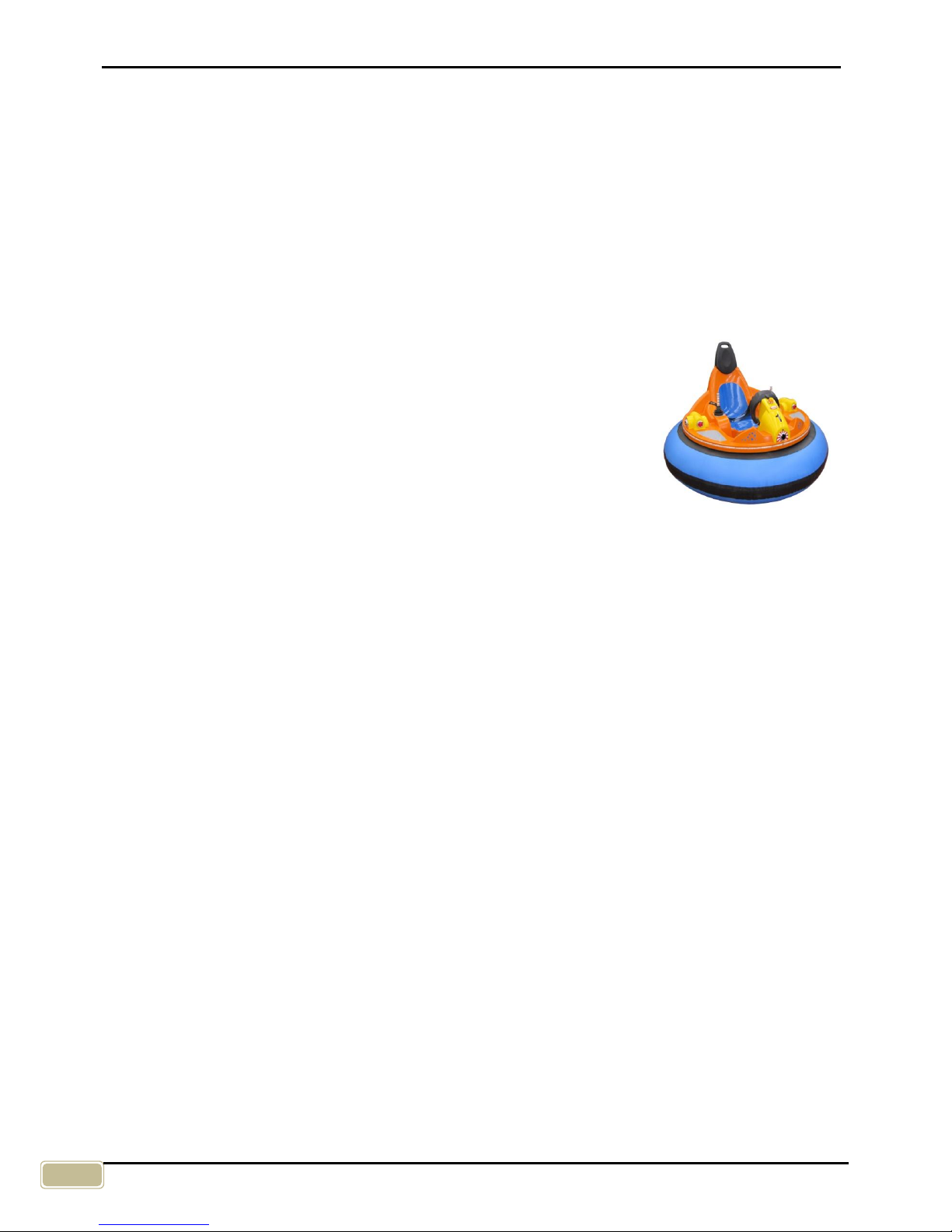
4. SERIES AND MODELS
The Automatic Games of the “Bumper Car” series are manufactured
in the following models:
SPACE BUMPER
ICE BUMPER
HYPER BUMPER
MINI BUMPER
“Hyper Bumper” version
The "Hyper Bumper" version of our "Bumper Car" is fitted with the "Shoot & Spin" system, which uses
infrared devices to make the game all the more involving and entertaining. Shooting infrared rays at
opponents and hitting “target” sensors will cause the opponents’ mini-vehicles to stop and spin for a few
seconds.
"Shoot & Spin" system – main components:
Dashboard display;
Infrared “firing” device (located at the front of the mini-vehicle);
“Target” sensors (3, located at the front and on the sides of the mini-vehicle);
Track edge display
5. TECHNICAL FEATURES
The Automatic Games of the “Bumper Car” series have been designed and manufactured by
Eurogames according to the most advanced technologies and using strong iron structures protected by
beautiful shockproof finishes and fibreglass covers which insulates and protects against any accidental
or occasional tampering.
Onto the metal structure and into the Bumper’s body are located the power unit and electronic card. The
“Bumper Car” is equipped with a direct current battery-fed electric engine welded onto the metallic
structure.
The Bumper’s functions are controlled by the electronic board having inside a power unit and a
microprocessor. The Eurogames Automatic Games are very practical and have been designed and
manufactured to offer high performances.
The delivery package from Eurogames contains: the machine, the battery charger the Maintenance
handbook and if required by the customer the batteries.
Page 7
Eurogames Srl – Operation and maintenance handbook – BUMPER CAR & MINI BUMPER CAR
7
Technical data
Model
Height
(cm)
Height by
open room
(cm)
Width
(cm)
Length
(cm)
Weight *
(cm)
SPACE BUMPER 115 ~ 180 170 170 120
ICE BUMPER 115 ~ 180 170 170 120
HYPER BUMPER 115 ~ 180 170 170 120
MINI BUMPER 105 ~ 115 120 120 115
(*) Weight of the machine without battery.
The safety and stability of the “Bumper Car” Automatic Games are assured by the centre of gravity
located in central position close to the ground.
Adjustable parameters
sound and noise volume;
race time: from 30 to 990 seconds;
adjustable speed from 10% to 100%(from 1 to 8 km/h conforming to the country safety
regulations);
customised coins.
Characteristic parameters
electric power supply: 1 or 2 batteries, 12 V, 120 Ah or 80 Ah;
Mini 12 V model battery life: approx. 4-5 hours;
model battery life: approx. 5-6 hours;
5 and 12 Volt auxiliary circuits;
protection appliances: IP 53 for the 12/24V and 5V components;
storage conditions: temperature from -20°C to +50°C, concerning humidity from 30% to 95%;
running conditions: temperature: from +5°C to +40°C, concerning humidity from 40% to 90%.
pneumatic pressure. 2 bars.
6. MANUFACTURER
The “Bumper Car” series Automatic Games are manufactured by:
Eurogames S.r.l.
Via Degli Scavi, 41 Tel +39 0543 796665
47122 FORLÌ / ITALY fax +39 0543 722727
7. COMPLIANCE WITH NORMS AND DIRECTIVES
The “Bumper Car” series Automatic Games comply with all regulations and directives listed in the
Declaration of Conformity.
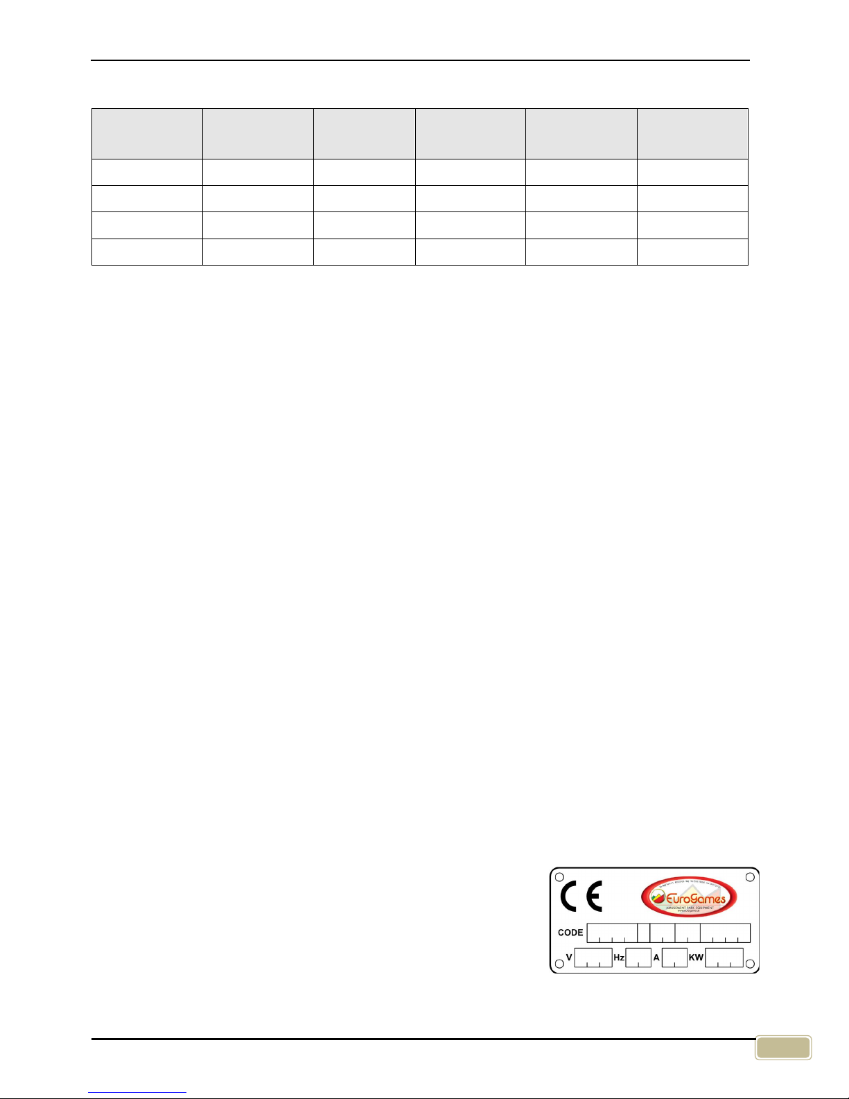
8. IDENTIFICATION PLATE
The identification plate, located in a visible position on the body, gives
the manufacturer’s identification data and the characteristic technical
data: code, power supply type, absorbed power. These elements are
necessary when asking the Manufacturer technical assistance or
spare parts.
Page 8
Eurogames SRL – Operation and maintenance handbook – BUMPER CAR & MINI BUMPER CAR
8
9. FUNCTIONING
The Automatic Games of the “Bumper car” series have been designed to be used in public places like
game-halls, commercial centres, amusement parks, fun-fairs and public gardens with specific tracks for
these vehicles.
CAUTION
The Automatic Games of the “Bumper car” series have not been conceived to comply with
the road traffic regulations. Therefore, any and all uses outside the specific tracks is
expressly forbidden.
The electric components of the “Bumper car” series Automatic Games are suitably
protected against humidity. However, they must not be dip in water, they must be
protected against rain, water jets and must not remain in contact with wet bodies. The
power supply nominal voltage does not exceed 24 Vdc.
The components of the “Bumper car” series Automatic Games in contact with electric
current are well insulated and mechanically protected. The internal harness voltage and
that supplied to the coin-box is 12 or 24Vdc. However, as for all appliances with electric
components, it is compulsory to comply with the instructions of this manual and to adopt
the normal precautions for preventing electric shocks when using the game.
ATTENTION
The Automatic Games of the “Bumper car” series must be used only on specific tracks
with level ground suitable for the race of mini vehicles, delimited and protected by a guard
having specific safety and manufacture characteristics.
We recommend to use tracks produced by Eurogames company. If you use a different
track, it must be built on a flat surface, solid, with a load capacity of more than 250
kg/sqm.
The surface of the track should be smooth and regular. It can be made in concrete,
wood, plastic, synthetic or real ice.
ATTENTION
Do not lift the “Bumper Car” by the fibreglass body shell or by the inflatable ring as that
may damage them. Use appropriate lifting equipment.
ATTENTION
The conditions of the track, the “Bumper Car” series Automatic Game and the battery
charger must be checked at least every 15 days and after any long period of inactivity.
Page 9
Eurogames Srl – Operation and maintenance handbook – BUMPER CAR & MINI BUMPER CAR
9
Preliminary operations
Before starting the machine, carefully follow the steps below:
Mounting and connecting the battery
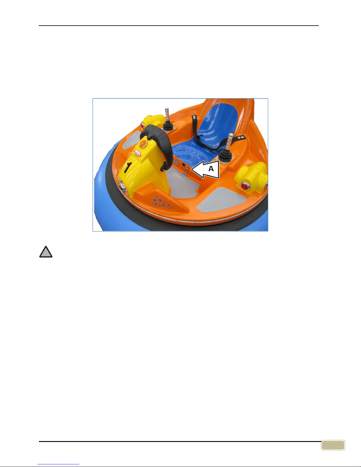
Follow these instructions as described and in the indicated sequence:
1. To detach the cover, turn the key and press the button located under the seat (zone A in fig. 1).
2. Lift the cover.
Fig. 1
ATTENTION
Do not carry out this operation with wet hands and always take the necessary precautions to
prevent electric shocks.
If the “Bumper car” is delivered with the battery charged, it must be used within 5-6 days;
after that time, the battery must be recharged regularly to avoid damage (see “battery
recharge”).
If the battery is “dry”, buy the specific liquid at a specialised centre, then proceed as
follows:
- pour in the liquid in the battery up to the maximum level,
- wait 3-4 hours, then charge the battery with the battery charger supplied,
- charge the battery for at least 8-10 hours before use.
If the “Bumper car” is supplied without battery, address to a specialised centre for the
purchase. The new battery must have the following dimensions (LxDxH) 33x17.5x22 (for
120 Ah batteries) or (LxDxH) 27x17x21 (for 80 Ah batteries). All batteries installed in the
Bumper Car must have the same amperage rating.
Page 10
Eurogames SRL – Operation and maintenance handbook – BUMPER CAR & MINI BUMPER CAR
10
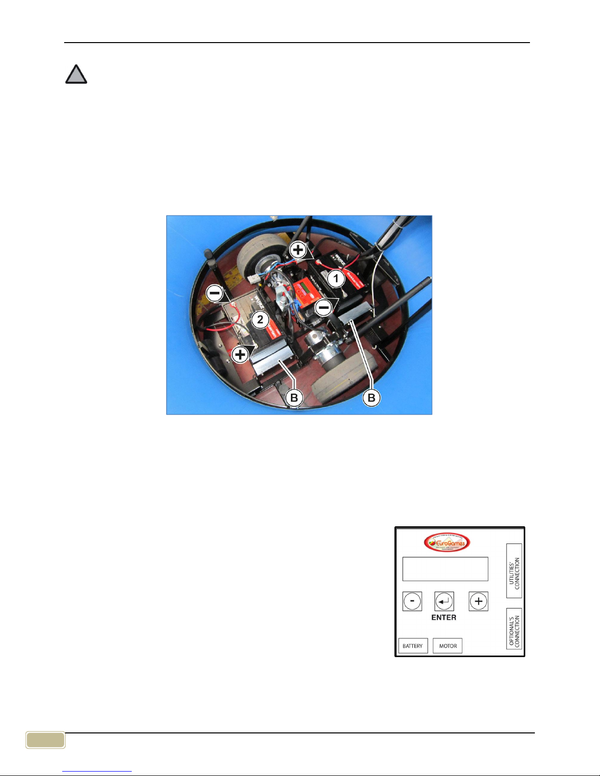
3. Position the first battery 1 (Fig.2).
ATTENTION
It is possible to install 80 Ah batteries inserting the spacers B or 120 Ah batteries by removing
the spacer B.
4. Connect the positive terminal marked with + (plus) to the positive (+) pole onto the battery using the
red or brown cable;
5. Connect the negative terminal marked with – (minus) to the negative (-) terminal onto the battery
using the black cable.
6. Carry out the same procedure for the second battery 2 (Fig.2).
7. Shut the body making sure that it closes well. If necessary adjust the rubber blocks as described in
the concerning chapter.
Fig. 2
Tyre pressure
Check the pressure of the tyres which has to be 2 atmospheres.
Rubber dinghy pressure
Check the pressure of the tyres which has to be 0,18 bar / Atm. - 2,64 Psi - 18K Pa.
Setting the game time
It is possible to set the race time by programming the digital control box
(Fig.3). The adjustment range is between 30 and 990 seconds.(see
“DIGITAL TIMER” section).
Setting the sound volume
It is possible to set the volume programming the digital control box (see
“DIGITAL TIMER” section).
Fig. 3
Page 11
Eurogames Srl – Operation and maintenance handbook – BUMPER CAR & MINI BUMPER CAR
11
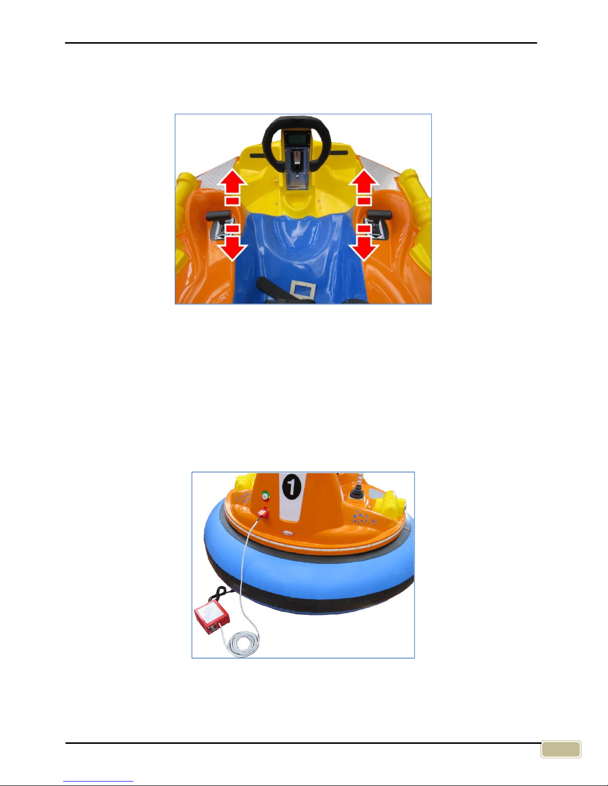
Setting the speed
The maximum speed must be set as a function of the size of the play area and of the type of players.
Program the digital timer to set up the maximum speed (see “DIGITAL TIMER” section).The real race
speed is adjustable by pushing more or less down the joysticks (Fig.4).
Fig. 4
Charging the battery
Charge the battery before using the “Bumper Car” the first time and every time the vehicle looses power
to avoid damage.
The “low battery” will be indicated acoustically. To prevent the batteries damages it’s important to charge
it regularly and when the vehicle loses power or indicated the conditions of low battery.
To charge the battery, connect the battery charger using the cable provided to the battery power socket
fitted on all models of the “Bumper Car” series (Fig.5). For further details please refer to the specific
chapter “BATTERY CHARGER”.
The batteries must be charged only with the supplied charger. It’s possible to replace them with full
batteries of the same features.
Fig. 5
Page 12

Eurogames SRL – Operation and maintenance handbook – BUMPER CAR & MINI BUMPER CAR
12
10. TESTING
For the manufacturing, tests, controls and inspections of its Automatic Games, Eurogames adopts the
criteria established by the international standards ISO 9000 for Quality Systems.
Before delivering the “Bumper Car” for use, it is however necessary to check for 3 (three) times its
correct functioning by idling, inserting a coin each time.
11. USE
CAUTION
While the “Bumper Car” is operational, always ensure all seatbelts are fastened and that any
minor in the driver’s seat be constantly supervised by an adult.
IMPORTANT
The Automatic Games from the “Bumper Car” series are not suitable for their functions,
dimensions and characteristics for children under 6 years old, unless accompanied by an
adult who is responsible. If the user has more than 6 years, but he is a minor, he must be
under strict supervision by an adult who is responsible for the entire duration of the race.
Before inserting the coin, have the user sit correctly in the “Bumper Car” and fasten the
safety belt.
The user must never be barefoot when using the “Bumper Car”.
Do not allow the user to get in or off when using the “Bumper Car”.
Start the “Bumper Car” using the remote. Do not start the “Bumper Car” until all users
have been seated and the seat belts have been securely fastened.
Do not leave the user unattended on the “Bumper Car” after the race.
Do not leave users alone close to the track of “Bumper Car”, whether standing still or
running.
When the “Bumper Car” game time is over, the user must be taken outside the track.
Make sure that the above precautions are adopted and intervene with decision if users do
not respect them. Take always into due account the typical unexpected behaviour of
children of this age.
Page 13
Eurogames Srl – Operation and maintenance handbook – BUMPER CAR & MINI BUMPER CAR
13
Let get in the user and make sure that he sits correctly in the driver’s position, than:
1. Check that the user places his feet correctly on the footboard, has the safety belts fasten and that the
joystick are not in gear.
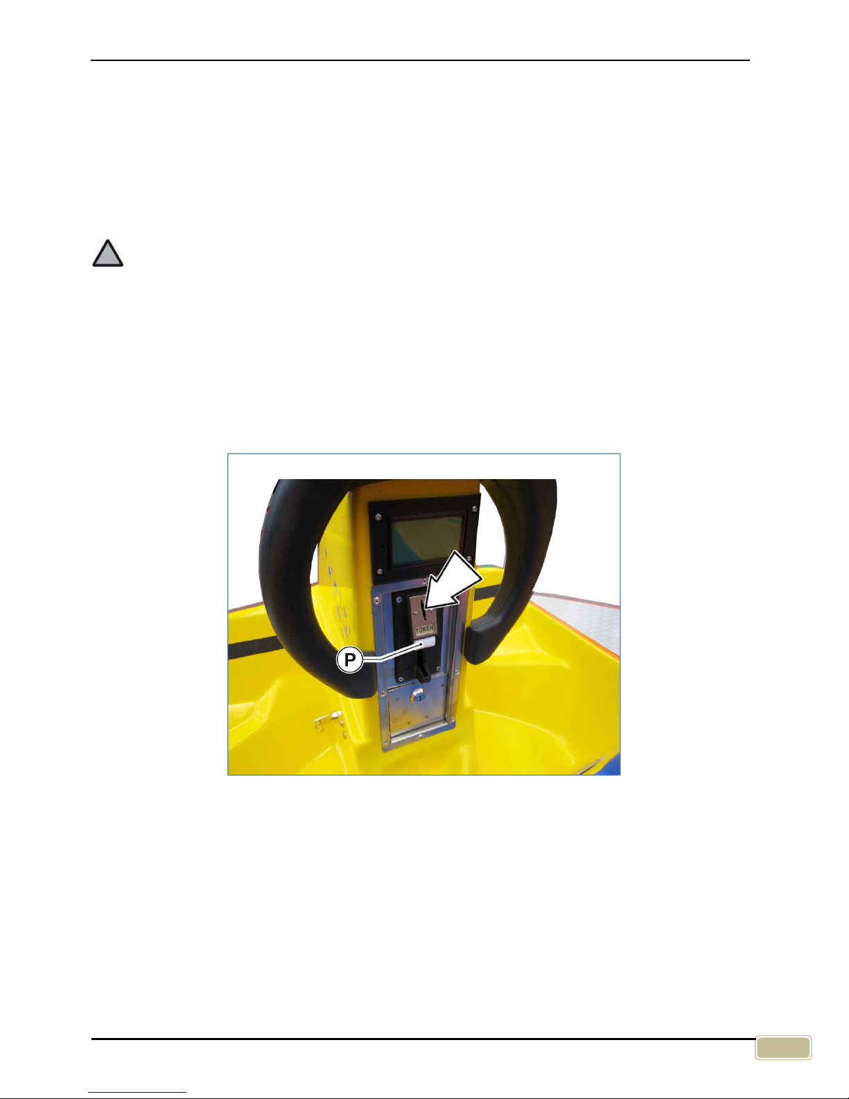
2. Let your user insert the coin in the coin-mechanism indicated by the arrow in Fig. 6 and wait for the
visual signal of machine ready (the front lights go on).
3. If front light car is not flashing, check that the token should not get stuck in the coin box. In this case
press the white button P (Fig. 6) or insert a new token.
4. when the machine signals that the machine is ready, the user has only to move the joysticks and the
“Bumper Car” will get starting.
ATTENTION
All the Automatic Games of the “Bumper Car” series have an automatic system that varies
gradually the speed with the aim to not allow sudden accelerations (it is an Eurogames’
exclusive).
5. If user has more than 6 years, but it is a minor must be followed visually by the parent or an adult
who is responsible for the entire race time.
6. When the “Bumper Car” begins running together with the sounds also the lights turn on. These will
stop when the game time will be over.
7. At the end of the race please control that all users are getting out of the “Bumper Car” properly and if
necessary help them. Help also users getting in the car until the beginning of the race.
Fig. 6
Page 14
Eurogames SRL – Operation and maintenance handbook – BUMPER CAR & MINI BUMPER CAR
14
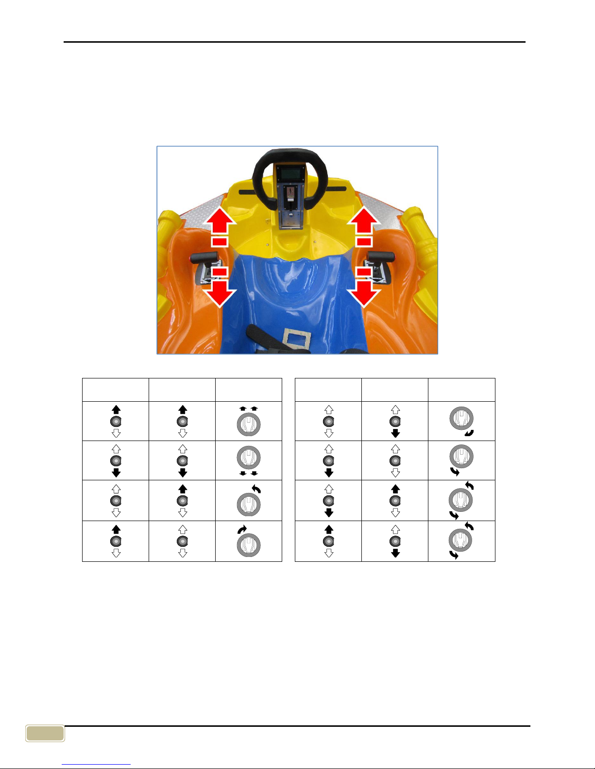
Functions of the joysticks
The “Bumper Car” Automatic Game is equipped with two joysticks placed at the right and left side of the
driving position (Fig.7).
The right joystick drives the right wheel, whereas the left joystick operates the left wheel and they can be
also moved for- and backwards.
The operating of a single or of both joysticks will carry out the movements described in the following
scheme.
Fig. 7
Left
joystick
Right
joystick
Movement
Left
joystick
Right
joystick
Movement
Page 15
Eurogames Srl – Operation and maintenance handbook – BUMPER CAR & MINI BUMPER CAR
15
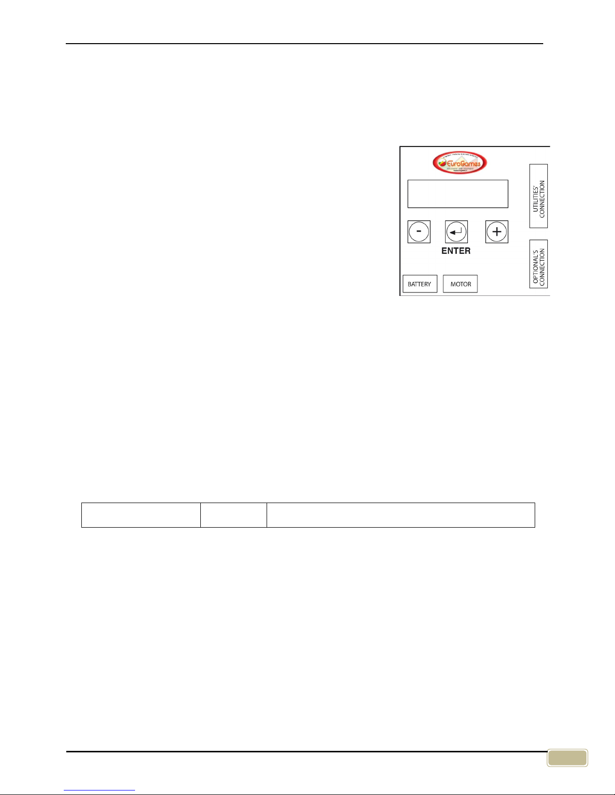
12. EG09 TIMER
Directions for Use
The timer device displays the current remaining game time and the percentage of battery charge. If you
press any of the three selection buttons (-, ENTER, +) it turns on the display light.
To modify any configuration parameter you can press the “+” or “-“
button until you see the parameter in the display. To modify its value
you have to press the “ENTER” button once and then you can use the
“+” or “-“ button. To confirm the new value you can press “ENTER”
button again to return to the list of available configuration parameters.
To enter the “Protected Menu” and modify its configuration parameters
you must be in the first “Main Menu” parameter (“time=000s Bat99%”).
You have to keep pressed “ENTER” button for at least 5 seconds. The
activation of the “Protected Menu” is shown as “< Protect Menu >
message.
To modify the configuration parameters you can use the same
procedure explained for the “Main Menu”. To exit the “Protected
Menu” you have to select the last list item (“ENTER for EXIT”) and press the “ENTER” button.
The modified parameters are immediately saved in the internal memory. It is suggested to remove the
power from the timer device after parameters changes before use it for normal operation again.
If no button is pressed for about 1 minute, the display returns to the first general parameter and exits
from the menu.
Radio Module
If the “RXTX” radio module for the remote control is mounted inside the timer device the
“RemoteSTART” parameter (inside the “Protected Menu”) selects the remote control function. If this
parameter is set to “On” the start of the game depends on the remote control “Start” button. If this
parameter is set to “Off” the game starts on coin insertion and the remote control can be used for
emergency “STOP/START” functions.
RemoteSTART=On On The timer device will wait the remote control START
command to start the game.
Page 16
Eurogames SRL – Operation and maintenance handbook – BUMPER CAR & MINI BUMPER CAR
16
“Main Menu” parameters
The parameters included in the main menu are the following: (some are not modifiable)
Time=000s Bat85% Time to end of game and battery charge level.
P.Counter=000000:00 Partial coins counter. The 2
digits on right side of “:” symbol show the
accumulated if the required coins for a game (Game-Coins) are not reach.
To reset the coins counter the previous option (Time, Bat) must be on screen. Press the “+” button for at
least 5 seconds. The following message will be shown.
ResetCounter=No
To reset the counter press “Enter” button and select YES with the “+”
button. The counter will be reset to 0.
Volume=07 Sound effects volume. It can be set from 1 to 30.
Game-Coins=01 Number of coins for a game.
If it is set to 0 there is no need of coins to start the
game. To enable this free game function the FREE COINS option on protected
menu must be set to ON.
Game-Time=120s Game time (seconds).
Speed-Forw=70% Maximum motor power Forward.
Speed-Rev=70% Maximum motor power Reverse.
Acceleration=080
Motor acceleration speed. Bigger number means faster acceleration.
Deceleration=080
Motor deceleration speed. Bigger number means faster deceleration.
RemoteControl=01 Identification number for remote control (1 –
32). This number allows you to set
parameters in the control box and START/STOP the game from a remote
control unit. Every car must have its own unique number otherwise the
programming of a single machine will fail.
RemoteSTART=On For this parameter explanation look at the “Radio Module” chapter.
Language=ENGLISH Language selection for audio messages:
ITALIAN , ENGLISH , FRENCH , GERMAN , SPANISH , GREEKE, PORTOG
Standby=20 Only
on Hyper Bumper: Time (minutes) for Standby function. If the Bumper is
not used for this time the LCD display and the LED ring is turned OFF.The 0
value disable the Standby function. The Bumper Car exit from the stanby
condition if a coin is inserted or if a Joystick button is pressed.
Wakeup=0 Only
on Hyper Bumper: Time (minutes) for Wakeup function. When the
Bumper Car is in Standby mode, this time sets a delay for a temporary makeup
function. The LED ring will be turned ON and a sound effects will be
played for
few seconds.
Bat=24.7v T=026° This parameter shows the battery voltage and the Timer internal temperature.
I1=000A I2=000A Real time motors current value.
Page 17

Eurogames Srl – Operation and maintenance handbook – BUMPER CAR & MINI BUMPER CAR
17
Protected Menu” parameters
The parameters included in the protected menu are the following: (some are not modifiable)
T.Counter=000000 Total coins counter. This counter cannot be reset (read only).
Effect=SPACE
This parameter selects the sound effect group type. This parameter depends on
sound module memory programming.
Coin-Mode=NORM
NORM: to start the game the number of coins-
match requested must be inserted. Coin
inserted during game play will be lost but counted by the counters.
ACC: to start the game the number of coins-
match requested must be inserted. Every
coin inserted during game play will increase game time.
AC P: to start the game the number of coins-
match requested must be inserted. Coins
inserted during game play are valid o
nly if the requested coins for 1 extra game are
reached.
FreeCoins(0)=Off This option enable the free play when “Coins” parameter is set to 0
W-Coin Count=No
If ‘YES’: when START is issued from the remote control, the coins counter will
increment as for normal coin insertion.
Low-Battery=On
This option enable the “LOW BATTERY” message when the game is over and
the battery voltage is low. The message is repeated every 7 seconds.
LoBat-Lev=005%
Battery level for “Low Battery” message. This value can be changed between
5% to 40% range.
Auto-Brake=On If “OFF”: motor will not brake when accelerator pedal is released.
if “ON”: motor will brake following “Deceleration” parameter.
End-Brake=On
If “ON”: after game time is finished and after “EndBrakeDelay”, motor brake
for 3 seconds.
EndBrakeDelay=0s Delay (seconds) after the game end to motor brake.
TelBrakeDelay=0s Delay (seconds) after remote control STOP command to motor brake.
Stop Lamp=Flash
When the timer is in STOP condition this option selects if the lamp must flash
or not.
J1.15=Emergency
This option selects the J1.15 input function.
If set to "Emergency": the timer will be reset if the J1.15 is activated.
If set to "FreeCoins": the J1.15 will act as coin insert but when this input is
deactivated the timer will be reset.
If set to “Security+” the J1.15 input must be connected to the safety belt switch.
This option enables the safety belt security functions.
Page 18

Eurogames SRL – Operation and maintenance handbook – BUMPER CAR & MINI BUMPER CAR
18
Pot1=128 -> +000 Joystick pot. control 1 reading value.
Pot2=128 -> +000 Joystick pot. control 2 reading value.
Pot Min=092 Pot. minimum value. See Joystick calibration procedure on User’s Manual.
Pot Max=155 Pot. maximum value. See Joystick calibration procedure on User’s Manual.
Pot DeadZone=015 Pot. neutral central zone. See Joystick calibration procedure on User’s Manual.
Pot2 Reverse =On Pot. control 2 direction reverse option.
Accel.X=0 Hit sensor threshold level for X direction.
This sensor detects hits from front and
back. Set it to 0 to disable this sensor. Optional function on request.
Accel.Y=3 Hit sensor threshold level for Y direction. This sensor detects hits from sides.
Set
it to 0 to disable this sensor. Optional function on request.
Accel.Z=0 Hit sensor threshold level for Z direction.
Not used in the current software
version.
Switch= - - - - - - - - GLHRKCSEF
Input status. Every input shown its own letter.
G=COIN, L=LOW, H=HIGH , R=RETRO, K=CLOCHE,
C=CLACSON, S=SENSOR , E=EMERGENCY, F=TURN LIGHT
Software V4.0BC Software version.
Other functions
- If no buttons are pressed for at least 60 seconds the screen returns to the main menu first item.
- During the over current alarm condition the display shown the “MotorHighCurrent” message. An
alarm sound like an horn is emitted and the game lamp is flashing. The alarm will reset automatically
after about 4 seconds.
- If the cooling fin temperature exceeds the set maximum, a “High Temperature” alarm appears, the
race ends and the motors stop. You must wait for the automatic alarm reset in order to be able to
start other races.
- When the game is over if the battery voltage is low a “LOW BATTERY” message is emitted every 7
seconds.
- If more than one coin is needed to start the game after the first coin is inserted the lamp starts to
blink and a sound message is played. The message depends on the language parameter selected.
Page 19

Eurogames Srl – Operation and maintenance handbook – BUMPER CAR & MINI BUMPER CAR
19
Connectors description
Fig. 9
PIN
J1 - DESCRIPTION
PIN
J2 - DESCRIPTION
J1.1 DO NOT USE
J2.1 Turn Lamp output 12/24v
J1.2 Ground
J2.2 Pot. 1 input
J1.3 Speaker output
J2.3 Reverse direction input
J1.4 NPN auxiliary output, 1A max.
J2.4 Joystick input
J1.5 LOW pedal input
J2.5 Horn input
J1.6 COIN input
J2.6 DO NOT USE
J1.7 Auxiliary 12/24V output (do not use)
J2.7 Pot. 2 input
J1.8 Magnetic sensor input
J2.8 5V output for Pot. Controls
J1.9 HIGH pedal input
J2.9 DO NOT USE
J1.10 Lamp output 12/24v
J1.11 Ground
J1.12 12/24v output, 1A max.
J1.13 DO NOT USE
J1.14 DO NOT USE
J1.15 Emergency input /FreeCoins / Security+
J2
J1
Page 20

Eurogames SRL – Operation and maintenance handbook – BUMPER CAR & MINI BUMPER CAR
20
13. WIRING DIAGRAM
Fig. 10
Page 21

Eurogames Srl – Operation and maintenance handbook – BUMPER CAR & MINI BUMPER CAR
21
14. REMOTE CONTROLLER EG-TEL8
Keyboard description
Key [START] [STOP]: These buttons can Start and Stop all the
enabled products at the same time. For safety reason the Stop
command is sent immediately. The [STOP] button has the
maximum priority on all other buttons pressed at the same time.
Key [STOP]: if this button is kept pressed for about 3 seconds all
the products in the radio range will be turned off (end game).
Key [1]: if this button is kept pressed for about 3 seconds 1 wireless
coin will be send to all the products in the radio range.
Key [2]: if this button is kept pressed for about 3 seconds 2 wireless coins will be send to all the
products in the radio range.
Key [3]: if this button is kept pressed for about 3 seconds all the products in the radio range will be
configured to start on coin insertion. In this case the remote controller can be used to stop all the
products in case of emergency. [START] key will restart them all after a Stop command.
Key [4]: if this button is kept pressed for about 3 seconds all the products in the radio range will be
configured to start on remote controller Start command. In this case, after a coin insertion, the product
waits the remote controller Start command.
Key [Arrow Up] [Arrow Down]: These buttons have no function in this software version.
Batteries
The remote control unit is powered by 2 common AAA
1.5V batteries. The replacement of the batteries is easy.
The bottom part of the case can be removed by
removing the 2 screws that fix it at the upper part of the
case (a cross screwdriver is needed).
IMPORTANT
During replacement please take care of the battery
polarity direction. Wrong position can damage the
remote control. To avoid problems with a possible acid
leakage remove batteries if the remote control unit will
be stored unused for a long time.
.
Page 22

Eurogames SRL – Operation and maintenance handbook – BUMPER CAR & MINI BUMPER CAR
22
15. REMOTE CONTROLLER EG09TEL
Functions
This remote control unit allow the remote configuration of products that mount the “EG09 Digital Timer”.
“Wireless Coin”, “Start”, “Stop” or “game End” commands can be sent to all the products or to a single
product. The products can be configured with its own number from 1 to 32.
A standard product is configured as number “1” during production. If control of a single product is
required the “RemoteControl” configuration parameter in the EG09 Digital Timer must be set correctly. In
this case a different number must be set in every available product (for more information please check
the EG09 Digital Timer Configuration Manual).
As an example here you can find a part of the EG09 Digital Timer Configuration manual.
RemoteControl
=01
Device number for remote control functions (1 to 32). If control of a single device is
required this number must be different in any device. If this number is not unique in all
devices there can be communication problems with the remote control unit.
Also when all the products are configured with a different number it still be possible to use the “START”,
“STOP” commands and other functions with the “ALL” destination number. This option control all the
products at the same time.
Keyboard description
[ON/OFF]: If this button is kept pressed for about 4 seconds the remote
control display will turn on or off. If pressed again for a short time the
backlight will be turned on or off. The remote control turns off
automatically after about 10 minutes if not used.
[START/STOP]: These buttons send a Start or Stop command to the
enabled products. They can be used when the remote control is off. In
this case the command will be sent to all the enabled products. If the
remote control unit is ON the command will be sent to the selected
device. The “Device Selected” option on screen can be changed to “ALL”
value or to a specific device number. Note: Start and Stop commands will
be sent on buttons release.
If the “START” button is kept pressed for about 4 seconds and released
a “Wireless Coin” is sent to the selected device.
If the “STOP” button is kept pressed for about 4 seconds and released
an “End” command is sent to the selected device. The running product
will stop as time end condition. This function may be not available in all
products.
[ALL]: Selects “ALL” as Device Selected” option. The remote control unit
will be ready to broadcast command to all the available and enabled products.
[+ / -]: The [+] and [-] buttons have different functions. The menu item can be selected or a specific
configuration parameter value can be changed (for more information please check the EG09 Digital
Timer Configuration Manual).
[SEL]: This button have the same function of the [ENTER] buttons on EG09 Digital Timer when
programming mode is enabled.
Page 23

Eurogames Srl – Operation and maintenance handbook – BUMPER CAR & MINI BUMPER CAR
23
[PROG]: This button enable or disable the programming mode.
ATTENTION
Enter programming mode only when the machine is not in use. Using the remote control to check
or alter parameter settings while the machine is in use may result in incorrect configurations and
anomalous functioning.
Display description
In the display there are some useful information: The internal software
version, “BAT=” battery charge value, “Device Selected:” Selected
product for next command transmission, “LastCommand=” last sent
command information.
EG09 Digital Timer Configuration – “ALL” devices
To setup all the device together the “ALL” option must be selected.
Press [PROG] button to enable the programming mode. The display
shown the configuration parameters. The [+] and [-] buttons select the
required parameter and the [SEL] button enable the editing mode. In
the editing mode a black blinking cursor is shown. The value can be
changed by [+] and [-] buttons.
The new value is sent to the device when the [SEL] button is pressed
again to exit editing mode. Please note that all the powered products
in the transmission range will receive the new parameter configuration.
Below you can find an example list of parameters that can be changed by the remote control unit when
“ALL” option is selected. Important: the available parameters may be different due to a possible
software update without notice (for more information please check the EG09 Digital Timer
Configuration).
Game-Time, Game-Coins, Coin-Mode, Volume, Speed-High, Speed-Low, Auto-Brake, EndBrake,EndBrakeDelay, TelBrakeDelay, End-Sensor, EndSensTime, Acceleration, Deceleration, LowBattery, Free Coins, Max Speed, EndGame Stop.
EG09 Digital Timer Configuration – Single device
To setup a single device its specific number must be selected as “Device Selected” option. Press
[PROG] button to enable the programming mode. In this case the remote control unit receive the
configuration parameter value directly from the selected EG09 Digital Timer included in the product. In
the “Single” configuration mode all the configuration parameters included in the EG09 Digital Timer can
be changed.
The [+] and [-] buttons select the required parameter and the [SEL] button enable the editing mode. In
the editing mode a black blinking cursor is shown. The value can be changed by [+] and [-] buttons. The
new value is sent immediately to the device. Press [SEL] button to exit editing mode.
If the remote control unit detect no transmission message from the device a “* No Signal *” message is
shown in the display. In this case check the power and the device number.
Page 24

Eurogames SRL – Operation and maintenance handbook – BUMPER CAR & MINI BUMPER CAR
24
“Hyper Bumper” gaming system configuration
To configure the “Hyper Bumper” gaming system (normally contained in the monitor casing) select the
value 32 under “Device Selected” and press the [PROG] button. The configuration parameters will
appear on the display. Use the [+] and [-] buttons to select the required parameter and the [SEL] button
to enter or exit the editing mode. A blinking square cursor will indicate the editing mode is active. If a
parameter is modifiable, its value can then be changed using the [+] and [-] buttons. Upon exiting the
editing mode, the modified parameter is recorded.
If the remote control is within range of the “Hyper” gaming system, the
following will appear on the display:
If no connection can be established between the remote control and the “Hyper” gaming system, the “*
No Signal *” message will appear on the display. When that happens, make sure the “Hyper” gaming
system is turned on and that the value 32 has been selected on the remote control.
The following is a list of the parameters that can be modified via the remote control.
[MODE]: (HYPER) selects the gaming mode. Currently only the “Hyper” option is available. The
“Hyper” mode is the standard Free for All combat mode. The first player to reach, without
drawing, the “Record” score – set using the “Record” parameter – wins a free ride (provided the
“Record” parameter has a value different from 0).
[TIME]: (min. 30 Sec.) sets the ride duration.
[RECORD]: (min. 0) sets the minimum score to reach to win a free ride. If the value is 0, no free ride will
be awarded.
[BUMPERS]: (min. 1) sets the number of Hyper Bumpers in the game. This parameter allows the system
to optimise the handling of all the elements in play. The value of this parameter should not be lower than
the actual number of Bumpers on the track. Important: The numbering of the Bumpers must increase
sequentially from 1. If one or more Bumpers are stopped or removed from the track, this parameter
should still be set to reflect the peak number of Bumpers in play.
[WINNER]: When this option is set to "SINGLE", the only player who has exceeded the record score and
scored at least one point more than other players, will receive a free game. If two or more players have
the same score no free game will be assigned. When this option is set to "MULTI" all the players who
have exceeded the record score will receive a free game.
[LANGUAGE]: (IT, UK, FR) selects the gaming language. The messages appearing on each Bumper’s
display will be in the selected language.
The “* - END - *“ message will be displayed at the end of the available parameters.
Batteries
The remote control unit is powered by 2 common AA 1.5V batteries. The replacement of the batteries is
easy trough a small batteries cover placed in the bottom part of the case.
IMPORTANT
During replacement please take care of the battery polarity direction. Wrong position can damage the
remote control. To avoid problems with a possible acid leakage remove batteries if the remote control
unit will be stored unused for a long time.
Do not connect any power supply unit to the remote control unit connectors to avoid damages.
********************
* - HYPER BUMPER - *
********************
Page 25

Eurogames Srl – Operation and maintenance handbook – BUMPER CAR & MINI BUMPER CAR
25
16. BATTERY CHARGER
Technical features
The battery charger consists of a painted, fireproof casing containing one to ten groups of the following
elements: electric transformer, electronic card, power plug and power cord, to recharge a single
“Bumper car” or more games at the same time.
The features of any single group are the following:
Width 15 cm
Height 9,5 cm
Depth 18 cm
Weight 3,5 Kg
Absorbed power 300 W
Power Supply 100-240 Vac 50/60 Hz
The battery charger is supplied together with the battery fed Automatic Games of the “Bumper car”
series, of which it is an integral part.
Fig. 25
Using the battery charger
Fig. 26
The Battery charger has been designed to be installed in public places like game-halls, commercial
centres, amusement parks, fun-fairs and public gardens with specific tracks for the Automatic Games of
the “Bumper car” series by Eurogames S.r.l.
A
B
C
D
Page 26

Eurogames SRL – Operation and maintenance handbook – BUMPER CAR & MINI BUMPER CAR
26
To recharge the batteries of the “Bumper car” series Automatic Games, operate as it follows:
Act on selector (E) in relation to battery type to be recharged:
Lead Acid or AGM / Sealed / Gel
ATTENTION
DO NOT RECHARGE the hermetic AMG/GEL batteries with the switch set to the LEAD ACID
function as they could be damaged.
Plug in the battery charger to the low voltage mains (220 V).
Connect the battery charger cable to the Automatic Game (Fig.19) using the special safety
connector against polarity inversion.
The battery charger condition is signalled by the on/off turning of the coloured warning lights on
the front panel, and namely:
Pos.
Reference
Signal
Meaning
A
Ready Yellow blinking Battery disconnected - standby mode
B
Charging Red on Battery charge
C
End Charge Green blinking End of charge
C
End Charge Green on Battery charged
D
Error Red blinking Error condition
The battery charger enters the error mode:
- when the battery is dead;
- when the poles have been wrongly connected;
- when the battery voltage is other than the one required;
- when the battery is damaged;
- in the case of overheating of the battery charger
In such cases, refer to the instructions in the battery charger manual.
After the recharge, and if you have not to recharge any other Automatic Game, disconnect the
battery charger from the vehicle and from the mains and store it suitably.
Safety
ATTENTION
The battery should not be dip in water or placed closed to wet parts.
Disconnect the power cord before displacing the battery charger.
Ensure the power cord of the battery charger is steadily protected and not damaged.
Plug the battery charger only after having checked the mains voltage is that given in the
plate located on the battery charger external casing.
Do not connect the battery charger to industrial mains. This connection could alter the
compliance with the uniform standards on electromagnetic compatibility; as a
consequence it could result in electromagnetic troubles, and cause similar troubles which
could jeopardize the functioning of other appliances. Before plugging, ensure the power
socket is protected by a thermal switch, with an amperage corresponding to that given on
the plate located on the battery charger, and by a differential switch with suitable cut-off
power and sensitivity. Do not connect more battery chargers downstream the same
thermal switch. The installation and use condition of the battery charger must be checked
at least every 15 days and after any long inactivity period.
Periodically check the condition of the cable and of the power plug, and the efficiency of
the differential protection of the battery charger (every 15 days).
Page 27

Eurogames Srl – Operation and maintenance handbook – BUMPER CAR & MINI BUMPER CAR
27
The battery charger should not be tampered or modified by the user. The EuroGames
products meet the established standards. Repair works should be carried out only by
specialized and authorized technicians. Any repair work carried out by non qualified or
authorized people could result in accidents or damages to the users. Before any
intervention, ensure the switch upstream the plug connecting the battery charger to the
power supply line is switched off.
Do not lay loads on the power cord. Keep off the power cord.
Do not cover the battery charger when functioning; do not close the ventilation grilles of
the plate casing.
17. MAINTENANCE
ATTENTION
Any and all maintenance operations must be carried out only by qualified people, authorized by
the “Bumper car” owner or manager.
Checks and inspections
General:
Regularly check the vehicle condition, and above all any connection point and part
subject to wear. Immediately replace any defective part using only EuroGames
original spare parts.
Electric:
Handling with care, regularly check the electric installation, the socket connections
and the protection caps after disconnecting the battery to prevent any electric
shock. If some defects are found, the “
Bumper car
” cannot be used and, above
all, cannot be connected to the battery charger.
Lead acid battery:
Regularly check the battery condition. When running, after every 2 operation
hours, the battery must be recharged for 12 hours. Periodically check the fluid
level and, when necessary, top up with distilled water.
Do not permit that the battery downloads too much, recharge it when the acoustic
and visual signal (LOW BATTERY) of the machine indicates it.
If the machine is not used for long periods, the Battery must be loaded
periodically, at least once a Month.
ATTENTION
The battery life is 18 months approx.
The exhausted battery must be disposed of by an authorized centre.
Visually inspect the “Bumper car” many times per day and let it undergo a functioning test
daily.
The “Bumper car” must not be tampered or modified by the Customer.
Repair works should be carried out only by adult, skilled and authorized people to prevent
accidents and damages to the users.
The Automatic Games of the “Bumper car” series supplied by EuroGames S.r.l. and the
battery charger have been manufactured according to the EC directives; if the local laws
require special installation conditions, make sure that these provisions do not imply
changes of the “Bumper car” or battery charger characteristics.
Page 28

Eurogames SRL – Operation and maintenance handbook – BUMPER CAR & MINI BUMPER CAR
28
18. CLEANING
This operation must be carried out daily when the “Bumper car” is in the parking area. With a wet
sponge or cloth and, if necessary, suitable house detergents clean only the external surface of the
“Bumper car”, then dry. Keep the body inside clean, and especially the pedal area. Clean the joystick
at least twice a day with an hygienic product. Ensure the coin slot is not obstructed.
ATTENTION
When cleaning the car, do not use sharp, pointed or abrasive objects and/or abrasive, solvent or
corrosive substances.
Coin collection
Open the coin collection box using the key provided and remove it from its housing.
19. SHELTERING
After a careful cleaning and lubrication of all mechanical parts, the “Bumper car” must be sheltered in a
dry place and suitably protected against bad weather and dust.
If the mini-vehicle is not used for long periods, recharge the batteries at least once a month.
ATTENTION
Do not pile up more Automatic Games.
Before sheltering the “Bumper car”, disconnect the cables, remove the battery and protect
the terminals. Do not carry out this operation with bare hands.
Do not turn the battery upside down.
During sheltering, keep the battery in a dry place and charge it at least once a month.
20. CHANGING THE TIRES
To substitute the tyre:
1. Deflate the rubber dinghy removing the cap A and pushing on the red B valve (Fig. 20a). Push on
the rubber dinghy to deflate it easier.
2. Raise a little bit the “Bumper Car” and place some clamps under the frame.
3. To change the tyre unscrew the nut by a key size 24 (Fig.19).
Fig. 19
Page 29

Eurogames Srl – Operation and maintenance handbook – BUMPER CAR & MINI BUMPER CAR
29
Changing the rubber dinghy
To change the rubber dinghy do as follows:
1. Deflate the rubber dinghy removing the cap A and pushing on the red B valve (Fig. 20a). Push on
the rubber dinghy to deflate it easier.
2. When the rubber dinghy is completely deflated disconnect the electric wirings of the battery charge
plug and of the two control boxes.
3. Remove the fixing screws C (Fig. 20b) of the gas springs keeping the body raised.
4. Remove the straps D anchoring the body shell’s power cables to the chassis.
5. Remove the anchoring bolt E.
6. Place carefully the body on the ground without damaging it.
7. Remove the rubber dinghy and replace it.
8. Inflate the new rubber dinghy by the supplied pump(Fig.20d).
Fig. 20a
Fig. 20b
Fig. 20c
Fig. 20d
Page 30

Eurogames SRL – Operation and maintenance handbook – BUMPER CAR & MINI BUMPER CAR
30
Adjusting of the body’s supporting rubber blocks
In some points of the frame are present the rubber blocks E (Fig.21). These have the aim to avoid the
direct contact between the body and the iron frame.
When closing the body, the body has to lean perfectly on the rubber blocks.
If this does not happen, adjust them as below described:
1. Raise the body.
2. Unscrew the nut F of the rubber block to adjust.
3. Screw or unscrew the rubber block to adjust its height.
4. Fasten the nut F.
5. Close the body and make sure that it is perfectly leant. If necessary repeat the adjustment operation.
Fig. 21
21. “HYPER BUMPER” DISPLAY CONTRAST SETTING
To set the display contrast, use a small flat-head screwdriver to turn the screw inside hole A (fig.
22).Take care not to exert too much pressure on the screw, as you may damage it.
Fig. 22
Page 31

Eurogames Srl – Operation and maintenance handbook – BUMPER CAR & MINI BUMPER CAR
31
22. JOYSTICK CALIBRATION
Enter the “Protect” menu.
Use the “+”button to scroll to the “Pot1” option. Keeping the Joystick 1 (right) in the centre
position, ensure the value returned on the display is above 118 and below 138.
Use the “+” button to scroll to the “Pot2” option. Keeping the Joystick 2 (left) in the centre
position, ensure the value returned on the display is above 118 and below 138.
If the values for Pot1 or Pot2 are not between 118 and 138, change the position of the board
located next to the Joystick until the correct value is returned (the centre value of 128 should be
used as reference).
Using the “Pot2” option, push the Joystick 2 (left) fully forward and backward, taking note of the
minimum and maximum values returned on the display.
Use the “-“ button to return to the “Pot1” option. Push the Joystick 1 (right) fully forward and
backward, taking note of the minimum and maximum values returned on the display.
Use the “+” button to scroll to the “Pot Min” option, press the “Enter” button, and use the “+” and
“-“ buttons to change the value. The value of “Pot Min” must be set to equal to the higher of the 2
minimum potentiometer values, plus 8. Press the “Enter” button to return to the menu.
Use the “+” button to scroll to the “Pot Max” option, press the “Enter” button, and use the “+” and
“-“ buttons to change the value. The value of “Pot Max” must be set to equal to the lower of the 2
maximum potentiometer values, minus 8. Press the “Enter” button to return to the menu.
Use the “+” button to scroll to the “Dead Zone” option, press the “Enter” button, and use the “+”
and “-“ buttons to change the value. The value should be set to 20. Press the “Enter” button to
return to the menu.
Example
Pot1
Pot2
Pot1 Centre Position = 132 Pot2 Centre Position = 125
Pot1 Minimum Value = 68
Pot2 Minimum Value=
71
Pot1 Maximum Value =
164
Pot2 Maximum Value = 176
Therefore, the settings are as follows:
o Pot Min = 79 (71+8, 71 is the higher of the 2 minimum values of Pot1 and Pot2)
o Pot Max = 156 (164-8, 164 is the lower of the 2 maximum values of Pot1 and Pot2)
o Dead Zone = always set to 20
23. SPARE PARTS
Recommended spare parts
With a fleet of 8/10 “Bumper Cars”, the customer should have the following spare parts in stock:
N. ... 1 ..... Digital control box
N. ... 2 ..... Joysticks
N. ... 2 ..... Coin-mechanism micro switches
N. ... 2 ..... 80 Ah fuses
N. ... 1 ..... 20 Ah fuse
N. ... 1 ..... Remote control with two buttons
Page 32

Eurogames SRL – Operation and maintenance handbook – BUMPER CAR & MINI BUMPER CAR
32
24. SPARE PARTS TABLES
Ed. 01/14
.0
Mod. BUMPER CAR SPACE/ICE
Cod. PB5-B500 / PB5-B501
TAV. 1
12
1
3
69
406281
15
18
27
20
60
21
72
25
9
7 10
7 10
6 5
36
13
16 17
52
35
23 24
11
2
19
23
7 8
A
A
A
A
58
61
59
38
Page 33

Eurogames Srl – Operation and maintenance handbook – BUMPER CAR & MINI BUMPER CAR
33
BUMPER CAR MOD.SPACE/ICE TAV_1 cod. PB5-B500
Ref. Code Description
001 0155 060 LOCK
002 0306 M48 COIN MECHANISM DOOR
003 0307 COIN BOR FOR M48 COIN MECHANISM DOOR
005 M-STA002169 BODY LOCKING COMPLETE
006 T-C000608 45050 LOCK
007 0523 24V LED GLASS LIGHT BULB
008 0340 GRID LAMPHOLDER D.50 WITHOUT LIGHT BULB
009 SS1-2495 BUMPER CAR BODY
010 0341 STAINL.STEEL LAMPHOLDER D.50 WITHOUTBULB
011 3137 COIN MECHANISM MICROSWITCH
012 0131 M48 COIN MECHANISM
013 0167 SAFETY BELTS
015 M-STA001588 BUMPER CAR HEADREST
016 0179 RED BATTERY CHARGER PLUG/SOCKET
017 0206 RED SUPPORT FOR 24V BATTERY CHARGER PLUG
018 M-L001193 FIXING CLAMP FOR LEFT GAS SPRING
019 M-L001192 FIXING CLAMP FOR RIGHT GAS SPRING
020 M-STA002036 JOYSTICK WITH POTENTIOMETER
021 M-C001262 PLASTIC PROTECTION FOR JOYSTICK
023 EG02251 BOARD EG-JOY
024 M-CE001312 JOYSTICK SENSOR
025 T-C000211 MICROSWITCH FOR JOYTSTICK
027 M-STA001589 BUMPER CAR HANDLE
035 MA1-1166 SPACE/ICE BUMPER RUBBER TUBE
036 7063 VALVE CAP FOR RUBBER DINGHY
038 V-C001755 ELECTRIC INFLATION PUMP
040 M-CE002234 REAR PLEXIGLASS MINI/HYPER BUMPER CAR
052 EC0-2311 BUMPER CAR BODY WIRING
058 7043 INFLATE PUMP
059 B-C001714 RUBBER DINGHY REPAIR KIT
060 EL0-2398 LED STRIP 24 V IP65 5 MT
061 T-C001751 GAUGE FOR PLASTIC TUBE PRESSURE
062 EX02245 BATTERY CHARGE INDICATOR BLM 24V
069 EJ0-2758 JOYSTICK FORW.
072 EI0-2375 JOYSTICK RED PUSH BUTTON
081 EL0-2361 12V LED STRIPE 5cm. WHITE
Page 34

Eurogames SRL – Operation and maintenance handbook – BUMPER CAR & MINI BUMPER CAR
34
Mod. BUMPER CAR SPACE/ICE
Cod. PB5-B500 / PB5-B501
TAV. 2
Ed. 01/14
.0
37
22
49
46
32
67
68
30
41
46
51
66
47
45
45
45
31
56
28
55 54
63 14 22
3229
53 56
43
16
44
44
42 65 64
65
22
64 42
39
50
57
53
34
55
68
67
41
70
48
56 54 53 55
48
Page 35

Eurogames Srl – Operation and maintenance handbook – BUMPER CAR & MINI BUMPER CAR
35
BUMPER CAR MOD.SPACE/ICE TAV_2 cod. PB5-B500
Ref. Code Description
014 0100 LOUDSPEAKER
016 0179 RED BATTERY CHARGER PLUG/SOCKET
022 0197 30xH20 ANTI VIBRATING
028 M-LT000569 MOTORIZED WHEEL HUB
029 M-STA001995 RTX EG09 BUMPER CAR DIGITAL CONTROL BOX
030 0291 80 AMP MAXI FUSE FOR DIGITAL CONTROL BOX
031 M-LT001643 BUMPER CAR RIGID WHEEL
032 M-C001182 GAS SPRING
034 0293 20 AMP. FUSE
037 T-STA001479 COMPLETE BATTERY ELASTIC
039 6212 BODY LOCKING POINTED PIN
041 M-C001873 CASTIR WHEEL D.80 BUMPER CAR
042 G-CE000576 24V MOTORIZED
043 0298 D.10 CABLES FOR HERMETIC BATTERY
044 0168 GREY BATTERY CHARGER PLUG/SOCKET
045 0553 CABLE TERMINALS FOR HERMERTIC BATTERY
046 0618 12V 120AH HERMETIC BATTERY
047 M-STA001731 RIGID WHEEL BUMPER CAR
048 M-STA001558 COMPLETE WHEEL 4.10/3.50-5 MOTOR.
049 PA1-1595 BATTERY CHARGER 2011 24V
050 M-STS001861 BODY LOCKING
051 EC0-2314 BUMPER CAR R,3 FRAME WIRING
053 3111 4.10/3.50-5 INNER TUBE
054 3154 4.10/3.50-5 TYRE
055 T-CE000566 5P. MOTORIZED WHEEL RIM WITHOUT BUSHING
056 T-CE000565 5P. MOTORIZED WHEEL RIM WITH BUSH
057 M-C001209 4.10X3.50.5 STUD PROFILE TYRE
063 T-L000196 LOUDSPEAKER COVER
064 3170 MINI CAR ENGINE BRUSH
065 0275 BLUE PLUG/SOCKET FOR ENGINE
066 T-STA001169 4,10X3,50-5 COMPLETE WINTER WHEEL
067 0245 RUBBER SUPPORT FIXING BRACKET
068 0246 6CM RUBBER SUPPORT FOR PROTECTION
070 M-STS002146 HYPER BUMPER CAR FRAME
Page 36

Eurogames SRL – Operation and maintenance handbook – BUMPER CAR & MINI BUMPER CAR
36
Ed. 01/14
.0
Mod. BUMPER CAR HYPER
Cod. PB5-B502 TAV. 1
79
77
12
76
75
LCD
RGBA
IRTX
IRXC
SW
IRXL
IRXL
1
3
40
62
74
80
73
81
15
18
79
77
27
9
4
78
6 5
36
13
16 17
35
11
2
71
72
77
79
19
7 8
A
A
20
21 25
23 24
A
A
69
52
58
61
59
38
82
23
Page 37

Eurogames Srl – Operation and maintenance handbook – BUMPER CAR & MINI BUMPER CAR
37
BUMPER CAR MOD.HYPER TAV_1 cod. PB5-B502
Ref. Code Description
001 0155 060 LOCK
002 0306 M48 COIN MECHANISM DOOR
003 0307 COIN BOR FOR M48 COIN MECHANISM DOOR
004 EL0-2360 24V LED STRIPE
005 M-STA002169 BODY LOCKING COMPLETE
006 T-C000608 45050 LOCK
007 0523 24V LED GLASS LIGHT BULB
008 0340 GRID LAMPHOLDER D.50 WITHOUT LIGHT BULB
009 SS1-2162 BUMPER CAR BODY
011 3137 COIN MECHANISM MICROSWITCH
012 0131 M48 COIN MECHANISM
013 0167 SAFETY BELTS
015 M-STA001588 BUMPER CAR HEADREST
016 0179 RED BATTERY CHARGER PLUG/SOCKET
017 0206 RED SUPPORT FOR 24V BATTERY CHARGER PLUG
018 M-L001193 FIXING CLAMP FOR LEFT GAS SPRING
019 M-L001192 FIXING CLAMP FOR RIGHT GAS SPRING
020 M-STA002036 JOYSTICK WITH POTENTIOMETER
021 M-C001262 PLASTIC PROTECTION FOR JOYSTICK
023 EG02251 BOARD EG-JOY
024 M-CE001312 JOYSTICK SENSOR
025 T-C000211 MICROSWITCH FOR JOYTSTICK
027 M-STA001589 BUMPER CAR HANDLE
035 MA1-1166 SPACE/ICE BUMPER RUBBER TUBE
036 7063 VALVE CAP FOR RUBBER DINGHY
038 V-C001755 ELECTRIC INFLATION PUMP
040 M-CE002234 REAR PLEXIGLASS MINI/HYPER BUMPER CAR
052 EC0-2311 BUMPER CAR BODY WIRING
058 7043 INFLATE PUMP
059 B-C001714 RUBBER DINGHY REPAIR KIT
061 T-C001751 GAUGE FOR PLASTIC TUBE PRESSURE
062 EX02245 BATTERY CHARGE INDICATOR BLM 24V
069 EJ0-2758 JOYSTICK FORW.
071 EC02261 EG-SHT1-IRTX CABLE WITH LED
072 EC02263 CABLE EG-SHT1-IRXC
073 EC02264 EG-SHT1-IRXL CABLE
074 EC02262 EG-SHT1-SW CABLE
075 EC02260 EG-SHT1-LCD1 CABLE
076 EX02248 LCD DISPLAY MOD.EG-LCD1
077 EL0-2367 D50 INOX LAMP HOLDER
078 EC0-2295 EG-SHT1-RGB CABLE
079 EG02250 Board EG-IRX1
080 EX02246 CONTROL BOX EG-SHT1B
081 EL0-2361 12V LED STRIPE 5cm. WHITE
082 EI0-2375 JOYSTICK RED PUSH BUTTON
Page 38

Eurogames SRL – Operation and maintenance handbook – BUMPER CAR & MINI BUMPER CAR
38
Ed. 01/14
.0
Mod. BUMPER CAR HYPER
Cod. PB5-B502 TAV. 2
37
22
49
46
32
67
68
30
41
46
51
66
47
45
45
45
31
56
28
55 54
63 14 22
3229
53 56
43
16
44
44
42 65 64
65 64 42
39
50
57
53
34
55
68
67
41
70
48
56 54 53 55
48
22
Page 39

Eurogames Srl – Operation and maintenance handbook – BUMPER CAR & MINI BUMPER CAR
39
BUMPER CAR MOD.HYPER TAV_2 cod. PB5-B500
Ref. Code Description
014 0100 LOUDSPEAKER
016 0179 RED BATTERY CHARGER PLUG/SOCKET
022 0197 30xH20 ANTI VIBRATING
028 M-LT000569 MOTORIZED WHEEL HUB
029 M-STA001995 RTX EG09 BUMPER CAR DIGITAL CONTROL BOX
030 0291 80 AMP MAXI FUSE FOR DIGITAL CONTROL BOX
031 M-LT001643 BUMPER CAR RIGID WHEEL
032 M-C001182 GAS SPRING
034 0293 20 AMP. FUSE
037 T-STA001479 COMPLETE BATTERY ELASTIC
039 6212 BODY LOCKING POINTED PIN
041 M-C001873 CASTIR WHEEL D.80 BUMPER CAR
042 G-CE000576 24V MOTORIZED
043 0298 D.10 CABLES FOR HERMETIC BATTERY
044 0168 GREY BATTERY CHARGER PLUG/SOCKET
045 0553 CABLE TERMINALS FOR HERMERTIC BATTERY
046 0618 12V 120AH HERMETIC BATTERY
047 M-STA001731 RIGID WHEEL BUMPER CAR
048 M-STA001558 COMPLETE WHEEL 4.10/3.50-5 MOTOR.
049 PA1-1595 BATTERY CHARGER 2011 24V
050 M-STS001861 BODY LOCKING
051 EC0-2314 BUMPER CAR R,3 FRAME WIRING
053 3111 4.10/3.50-5 INNER TUBE
054 3154 4.10/3.50-5 TYRE
055 T-CE000566 5P. MOTORIZED WHEEL RIM WITHOUT BUSHING
056 T-CE000565 5P. MOTORIZED WHEEL RIM WITH BUSH
057 M-C001209 4.10X3.50.5 STUD PROFILE TYRE
063 T-L000196 LOUDSPEAKER COVER
064 3170 MINI CAR ENGINE BRUSH
065 0275 BLUE PLUG/SOCKET FOR ENGINE
066 T-STA001169 4,10X3,50-5 COMPLETE WINTER WHEEL
067 0245 RUBBER SUPPORT FIXING BRACKET
068 0246 6CM RUBBER SUPPORT FOR PROTECTION
070 M-STS002146 HYPER BUMPER CAR FRAME
Page 40

Eurogames SRL – Operation and maintenance handbook – BUMPER CAR & MINI BUMPER CAR
40
Ed. 01/14
.0
Mod. MINI BUMPER CAR 24V/12V
Cod. PB5-B550 / PB5-B551 TAV. 1
58
23
69
40
62
19
27
60
15
61
59
38
11
72
12
7 10
7 10
36
13
18
16 17
35
6
5
52
8
7
9
A
A
A
71
Page 41

Eurogames Srl – Operation and maintenance handbook – BUMPER CAR & MINI BUMPER CAR
41
MINI BUMPER CAR 24V TAV_1 cod. PB5-B550
Ref. Code Description
005 M-STA002169 BODY LOCKING COMPLETE
006 T-C000608 45050 LOCK
007 0523 24V LED GLASS LIGHT BULB
008 0341 STAINL.STEEL LAMPHOLDER D.50 WITHOUTBULB
009 SS1-2609 MINI BUMPER CAR BODY
010 0340 GRID LAMPHOLDER D.50 WITHOUT LIGHT BULB
011 3137 COIN MECHANISM MICROSWITCH
012 0131 M48 COIN MECHANISM
013 0167 SAFETY BELTS
015 M-STA001588 BUMPER CAR HEADREST
016 0179 RED BATTERY CHARGER PLUG/SOCKET
017 0206 RED SUPPORT FOR 24V BATTERY CHARGER PLUG
018 M-L002274 FIXING CLAMP FOR LEFT GAS SPRING
019 M-L002219 FIXING CLAMP FOR RIGHT GAS SPRING
023 EG02251 BOARD EG-JOY
027 M-STA001589 BUMPER CAR HANDLE
035 MA1-2214 MINI BUMPER CAR RUBBER TUBE
036 7063 VALVE CAP FOR RUBBER DINGHY
038 V-C001755 ELECTRIC INFLATION PUMP
040 M-CE002234 REAR PLEXIGLASS MINI/HYPER BUMPER CAR
052 EC0-2312 MINI BUMPER CAR R.3 BODY WIRING
058 7043 INFLATE PUMP
059 B-C001714 RUBBER DINGHY REPAIR KIT
060 EL0-2361 12V LED STRIPE 5cm. WHITE
061 T-C001751 GAUGE FOR PLASTIC TUBE PRESSURE
062 EX02245 BATTERY CHARGE INDICATOR BLM 24V
069 EJ0-2758 JOYSTICK FORW.
071 EL0-2398 LED STRIP 24 V IP65 5 MT
072 EI0-2375 JOYSTICK RED PUSH BUTTON
Page 42

Eurogames SRL – Operation and maintenance handbook – BUMPER CAR & MINI BUMPER CAR
42
Mod. MINI BUMPER CAR 24V/12V
Cod. PB5-B550 / PB5-B551 TAV. 2
Ed. 01/14
.0
32
22
49
46
30
29
22
46
51
66
47
45
45
45
31
56
28
55 54
63 14
32
53 56
43
16
44
44
42 65 64
65
41373
50
64 42
70
57
53
34
55
2
70
4
1
41
48
56 54 53 55
48
3922
Page 43

Eurogames Srl – Operation and maintenance handbook – BUMPER CAR & MINI BUMPER CAR
43
MINI BUMPER CAR 24V TAV_2 cod. PB5-B550
Ref. Code Description
001 3181 COIN BOX MINI CARS
002 M-STS002222 COIN BOX SUPPORT
003 M-STS002212 MINI BUMPER FRAME
004 0155 060 LOCK
014 0100 LOUDSPEAKER
016 0179 RED BATTERY CHARGER PLUG/SOCKET
022 0197 30xH20 ANTI VIBRATING
028 M-LT000569 MOTORIZED WHEEL HUB
029 M-STA001995 RTX EG09 BUMPER CAR DIGITAL CONTROL BOX
030 0291 80 AMP MAXI FUSE FOR DIGITAL CONTROL BOX
031 M-LT001643 BUMPER CAR RIGID WHEEL
032 M-C002233 GAS SPRING
034 0293 20 AMP. FUSE
037 T-STA001479 COMPLETE BATTERY ELASTIC
039 6212 BODY LOCKING POINTED PIN
041 M-C001873 CASTIR WHEEL D.80 BUMPER CAR
042 G-CE000576 24V MOTORIZED
043 0298 D.10 CABLES FOR HERMETIC BATTERY
044 0168 GREY BATTERY CHARGER PLUG/SOCKET
045 0553 CABLE TERMINALS FOR HERMERTIC BATTERY
046 0618 12V 120AH HERMETIC BATTERY
047 M-STA001731 RIGID WHEEL BUMPER CAR
048 M-STA001558 COMPLETE WHEEL 4.10/3.50-5 MOTOR.
049 PA1-1595 BATTERY CHARGER 2011 24V
050 M-STS001861 BODY LOCKING
051 EC0-2314 BUMPER CAR R,3 FRAME WIRING
053 3111 4.10/3.50-5 INNER TUBE
054 3154 4.10/3.50-5 TYRE
055 T-CE000566 5P. MOTORIZED WHEEL RIM WITHOUT BUSHING
056 T-CE000565 5P. MOTORIZED WHEEL RIM WITH BUSH
057 M-C001209 4.10X3.50.5 STUD PROFILE TYRE
063 T-L000196 LOUDSPEAKER COVER
064 3170 MINI CAR ENGINE BRUSH
065 0275 BLUE PLUG/SOCKET FOR ENGINE
066 T-STA001169 4,10X3,50-5 COMPLETE WINTER WHEEL
070 M-L002198 CONTROL BOX BRACKET
Page 44

Eurogames SRL – Operation and maintenance handbook – BUMPER CAR & MINI BUMPER CAR
44
Ed. 01/14
.0
Mod. MINI BUMPER CAR 24V/12V
Cod. PB5-B550 / PB5-B551 TAV. 1
58
23
69
40
62
19
27
60
15
61
59
38
11
72
12
7 10
7 10
36
13
18
16 17
35
6
5
52
8
7
9
A
A
A
71
Page 45

Eurogames Srl – Operation and maintenance handbook – BUMPER CAR & MINI BUMPER CAR
45
MINI BUMPER CAR 12V TAV_1 cod. PB5-B551
Ref. Code Description
005 M-STA002169 BODY LOCKING COMPLETE
006 T-C000608 45050 LOCK
007 0522 12V LED GLASS LIGHT BULB
008 0341 STAINL.STEEL LAMPHOLDER D.50 WITHOUTBULB
009 SS1-2609 MINI BUMPER CAR BODY
010 0340 GRID LAMPHOLDER D.50 WITHOUT LIGHT BULB
011 3137 COIN MECHANISM MICROSWITCH
012 0131 M48 COIN MECHANISM
013 0167 SAFETY BELTS
015 M-STA001588 BUMPER CAR HEADREST
016 0168 GREY BATTERY CHARGER PLUG/SOCKET
017 0205 BLUE SUPP.FOR 12V BATT.CHARGER SOCKET
018 M-L002274 FIXING CLAMP FOR LEFT GAS SPRING
019 M-L002219 FIXING CLAMP FOR RIGHT GAS SPRING
023 EG02251 BOARD EG-JOY
027 M-STA001589 BUMPER CAR HANDLE
031 M-LT001643 BUMPER CAR RIGID WHEEL
035 MA1-2214 MINI BUMPER CAR RUBBER TUBE
036 7063 VALVE CAP FOR RUBBER DINGHY
038 V-C001755 ELECTRIC INFLATION PUMP
040 M-CE002234 REAR PLEXIGLASS MINI/HYPER BUMPER CAR
052 EC0-2312 MINI BUMPER CAR R.3 BODY WIRING
058 7043 INFLATE PUMP
059 B-C001714 RUBBER DINGHY REPAIR KIT
060 EL0-2361 12V LED STRIPE 5cm. WHITE
061 T-C001751 GAUGE FOR PLASTIC TUBE PRESSURE
069 EJ0-2758 JOYSTICK FORW.
072 EI0-2375 JOYSTICK RED PUSH BUTTON
Page 46

Eurogames SRL – Operation and maintenance handbook – BUMPER CAR & MINI BUMPER CAR
46
Mod. MINI BUMPER CAR 24V/12V
Cod. PB5-B550 / PB5-B551 TAV. 2
Ed. 01/14
.0
32
22
49
46
30
29
22
46
51
66
47
45
45
45
31
56
28
55 54
63 14
32
53 56
43
16
44
44
42 65 64
65
41373
50
64 42
70
57
53
34
55
2
70
4
1
41
48
56 54 53 55
48
3922
Page 47

Eurogames Srl – Operation and maintenance handbook – BUMPER CAR & MINI BUMPER CAR
47
MINI BUMPER CAR 12V TAV_2 cod. PB5-B551
Ref. Code Description
001 3181 COIN BOX MINI CARS
002 M-STS002222 COIN BOX SUPPORT
003 M-STS002212 MINI BUMPER FRAME
004 0155 060 LOCK
014 0100 LOUDSPEAKER
016 0168 GREY BATTERY CHARGER PLUG/SOCKET
022 0197 30xH20 ANTI VIBRATING
028 M-LT000569 MOTORIZED WHEEL HUB
029 EX0-2509 EG09 12V 2M DIGITAL TIMER
030 0291 80 AMP MAXI FUSE FOR DIGITAL CONTROL BOX
031 M-LT001643 BUMPER CAR RIGID WHEEL
032 M-C002233 GAS SPRING
034 0293 20 AMP. FUSE
037 T-STA001479 COMPLETE BATTERY ELASTIC
039 6212 BODY LOCKING POINTED PIN
041 M-C001873 CASTIR WHEEL D.80 BUMPER CAR
042 M-CE000575 12V MOTORIZED WHEEL
043 0298 D.10 CABLES FOR HERMETIC BATTERY
044 0168 GREY BATTERY CHARGER PLUG/SOCKET
045 0553 CABLE TERMINALS FOR HERMERTIC BATTERY
046 0617 12V 80 AH HERMETIC BATTERY
047 M-STA001731 RIGID WHEEL BUMPER CAR
048 M-STA001558 COMPLETE WHEEL 4.10/3.50-5 MOTOR.
049 PA1-1594 BATTERY CHARGER 2011 12V
050 M-STS001861 BODY LOCKING
051 EC0-2314 BUMPER CAR R,3 FRAME WIRING
053 3111 4.10/3.50-5 INNER TUBE
054 3154 4.10/3.50-5 TYRE
055 T-CE000566 5P. MOTORIZED WHEEL RIM WITHOUT BUSHING
056 T-CE000565 5P. MOTORIZED WHEEL RIM WITH BUSH
057 M-C001209 4.10X3.50.5 STUD PROFILE TYRE
063 T-L000196 LOUDSPEAKER COVER
064 3170 MINI CAR ENGINE BRUSH
065 0275 BLUE PLUG/SOCKET FOR ENGINE
066 T-STA001169 4,10X3,50-5 COMPLETE WINTER WHEEL
070 M-L002198 CONTROL BOX BRACKET
Page 48

Eurogames SRL – Operation and maintenance handbook – BUMPER CAR & MINI BUMPER CAR
48
25. TROUBLESHOOTING
1 - The “Bumper Car” does not work.
a -
ensure the micro switch of the coin box is well connected and in efficient working order;
b -
ensure the battery and the motor connectors are properly connected;
c -
disconnect the connectors A-B (Fig.23) and connect them to a working “
Bumper Car
” control box
or to a spare control box;
d -
check if the 80 Ah fuse C (Fig.23) works and if necessary change it.
2 - The “Bumper Car” has no power.
a -
check the battery condition and recharge if necessary;
b -
have the battery checked by a qualified technician.
3 - The “Bumper Car” does not give out the typical running noise.
a -
Ensure the volume is properly adjusted;
b -
Ensure the loud speaker is in efficient running order and the contacts are undamaged;
c -
replace the timer.
4 - Time cannot to be adjusted.
a -
if the “
Bumper Car
” never stops and the warning light of the machine ready in the front of the
vehicle does not blink, replace the timer;
b -
replace the timer;
5 - The battery charger does not charge.
a -
ensure the mains power is supplied;
b -
check the contacts of the connectors;
c -
if, when connecting a down battery to the battery charger, the charge end is signalled at once
(green LED on), have the battery recharged at an authorized service centre or replace the battery;
d -
check the 20 Ah fuse being on the cable that connects the timer to the battery.
6 - The “Bumper Car” suddenly stops when it is operating regularly?
a -
this could be due to electronic components overheating;
b -
this could be due to engine overheating;
c -
if the cause is one of the above, let the “Bumper Car” cool down and it will resume working
properly afterwards. Should this problem occur again, we recommend adjusting Speed and/or
Ramp Up settings choosing lower values. Such settings are in the protected menu (see chapter
“DIGITAL CONTROL BOX”).
Fig. 23
Page 49

Eurogames Srl – Operation and maintenance handbook – BUMPER CAR & MINI BUMPER CAR
49
26. WARRANTY
Eurogames S.r.l. offers a warranty of one year from the purchase date stated in the sale
document.
The Manufacturer undertakes to make good by repair or replacement at its option any defect in
the “Bumper car” arising from faulty design, materials or workmanship which shall become
apparent within the warranty period.
The Manufacturer’s warranty does not extend to:
- damages arising from an improper use of the “Bumper car” (for instance, breaks)
- failures, defects and damages attributable to wear, and marginal defects which do not affect the
“Bumper car” value or functioning
- freights for the shipment of the “Bumper car” to the nearest assistance centre or to the
Manufacturer’s premises.
No claim will be considered if the purchaser let the machine repair by non authorized people or if
other than genuine parts manufactured by Eurogames S.r.l. are used.
The “Bumper car” return to the Eurogames S.r.l. premises or to the assistance centres
authorized by Eurogames S.r.l. must be carriage free.
The warranty extends to all the countries supplied by Eurogames S.r.l. directly or by its
authorized dealers, where no local laws or provisions expressly forbid a service covered by this
warranty.
Eurogames S.r.l. reserves the right to modify its products without undertaking to give prior
notice.
Eurogames S.r.l. accepts no liability for any consequential or other loss, damage or injury
resulting directly or indirectly from the use of the product. Any other claim is excluded, unless
expressly foreseen by the law.
Page 50

EC Declaration of Conformity
The manufacturer:
Eurogames S.r.l
Via degli Scavi, 41
47122 Forlì – ITALIA
Tel. 0543 796665
Fax. 0543 722727
declares that the following equipment:
Typology of Product
:
AUTOMATIC GAME
Series:
BUMPER CAR
Model:
BUMPER CAR / MINI BUMPER CAR
Identification Code
SB500 / SB550
According to the measures of
:
- EN 55012 Radio disturbance characteristics
- EN 61000-6-2 Immunity for industrial environments
- EN 61000-4-3 Testing and measurement techniques
- ESD EN 61000-4-2 Immunity and Transient Current Capability
According to the measures of
:
2004/108/EC EMC EN Directive
2006/95/EC Low Voltage EN Directive*
* Applied only to Battery charger provided along with this product.
if operated in accordance with all relevant safety instructions, electromagnetic compatibility
and installation included in the documentation.
Forlì, Italy
Date of declaration
: 25 February 2013
Signature of the legal representative of the company
:
Eurogames S.r.l.
Eurogames S.r.l. via degli Scavi, 41 Forlì (Italy) – Tel. 0543 796665 - Fax. 0543 722727 – Web Site: www.eurogames.it - E-mail: info@eurogames.it - P. I: 03624290403
Page 51

Eurogames Srl – Operation and maintenance handbook – BUMPER CAR & MINI BUMPER CAR
51
Via degli scavi, 41 - 47122 Forlì (ITALY)
Tel. +39 0543 796665 Fax. +39 0543 722727
www.eurogames.it - info@eurogames.it
 Loading...