

EuroFans Atlanta Owner's Instruction Manual

OWNERS INSTRUCTION
MANUAL
30”/76cm
Atlanta
INSTALLATION
OPERATION
MAINTENANCE
PAGE 1
CAUTION
READ INSTRUCTIONS CAREFULLY FOR SAFE INSTALLATION
AND FAN OPERATION. IF UNSURE CONSULT
A QUALIFIED ELECTRICIAN

PAGE 2
SUITABLE FOR 230V/50 CYCLE ELECTRICAL SUPPLY
Enquiries on installing your fan please call our help line on
01959-564440

PAGE 3
Safety Precautions
1. To ensure the success of the installation be sure to read the instructions and study the
diagrams thoroughly before commencing.
2. All electrical work should only be undertaken after disconnection of the power by
removing fuses or turning off the circuit breaker to ensure all pole isolation of the
electrical supply. If you are in any doubt the services of a qualified electrician should
be sought to ensure that all work is carried out in accordance with the I.E.E.
Regulations, current good practice and other national and local electrical codes.
3. Make sure that your installation sits will not allow the rotating fan blades to come into
contact with any object and that there is a minimum clearance of 150mm (6”) from the
blade tip to the wall or ceiling. Please note that the bigger this clearance is the better
the airflow from your fan will be. Ensure the blades are mounted at a minimum height
of 2.3 meters (7’6”) from the floor when the fan is installed.
4. The fixing point for the fan must be able to support a weight of ten times that of the net
weight of the fan. Net weights can be found on the bottom of the unit’s box. If you are
mounting the fan to a ceiling junction box, the box and it’s fixing must be able to
support the moving weight of the fan and must not twist or work loose.
5. The fan must be earthed.
6. Do not connect the fan motor to a dimmer switch. This may give an unsatisfactory
performance (motor hum) and cause damage to the motor.
7. It is not recommended that ceiling fans and gas appliances are operated in the same
room at the same time.
8. The fan must be turned off and stopped completely before reversing the fan direction.
This will prevent any damage to the motor of the unit or controller (if installed).
9. Do not insert anything into the fan blades while the fan is operating. This will damage
the blades and upset the balance of the unit causing the unit to wobble.
10. After the fan is completely installed make sure that all connections are secure
and tight to prevent any problems.
11. Because of the fan’s natural movement, some connections may loosen. Check the
support connections, brackets and blade attachments twice a year to make sure they
are all secure. If they are loose tighten with a screwdriver.
Note: The important safeguards and instructions given in this manual are not meant to
cover all possible conditions and situations that may occur. It must be understood that
common sense, caution and care are factors, which cannot be built into any product. These
factors must be supplied by the persons caring for and using the unit.
For installation advice, or in the unlikely event of damaged or missing parts please ring:
HELPLINE: (01959) 564 440

PAGE 4
Supplied Parts
One fan motor assembly
One round plate fitted with terminal block and top rubber washers.
One set of blades
One set of blade carriers
One screw-pack with balancing kit
One installation booklet.
Only supplied on units supplied with pre-fitted lights
One light fitting – factory fitted
One shade, one screw pack for light shade
Tools and Materials Required
Philips screwdriver
Blade screwdriver
Small electrical screwdriver
Electrical pliers
Step ladder
Wiring supplies as required by current electrical practice
Bulbs if a light fitting is fitted / to be fitted
In-line crimps or other suitable connectors if an extension rod in excess
of 760mm (30 inch) is to be fitted.
Before starting the assembly and installation of your fan please ensure the safety
precautions have been read and understood.
Installation Difficulties, Missing or Damaged Parts
If you have any difficulty in installing your fan/light or if you are unfortunate enough to
find that your fan have been dispatched with parts missing or damaged please contact
our help-line on (01959 564440). We will be very pleased to provide help or forward
replacements parts to your immediately.
In any communication with us please quote model reference, colour of the unit and the
part missing /damaged.
HELPLINE
01959 564440

PAGE 5
ASSEMBLING AND HANGING YOUR CEILING FAN
NOTE:
Before installing ensure that you have all poles disconnection of the electricity
supply and that you refer to q qualified electrician to ensure that all wiring is carried
out in accordance with I.E.E. Regulations, current good practice, national and local
electrical codes.
A. CLOSE TO CEILING MOUNTING
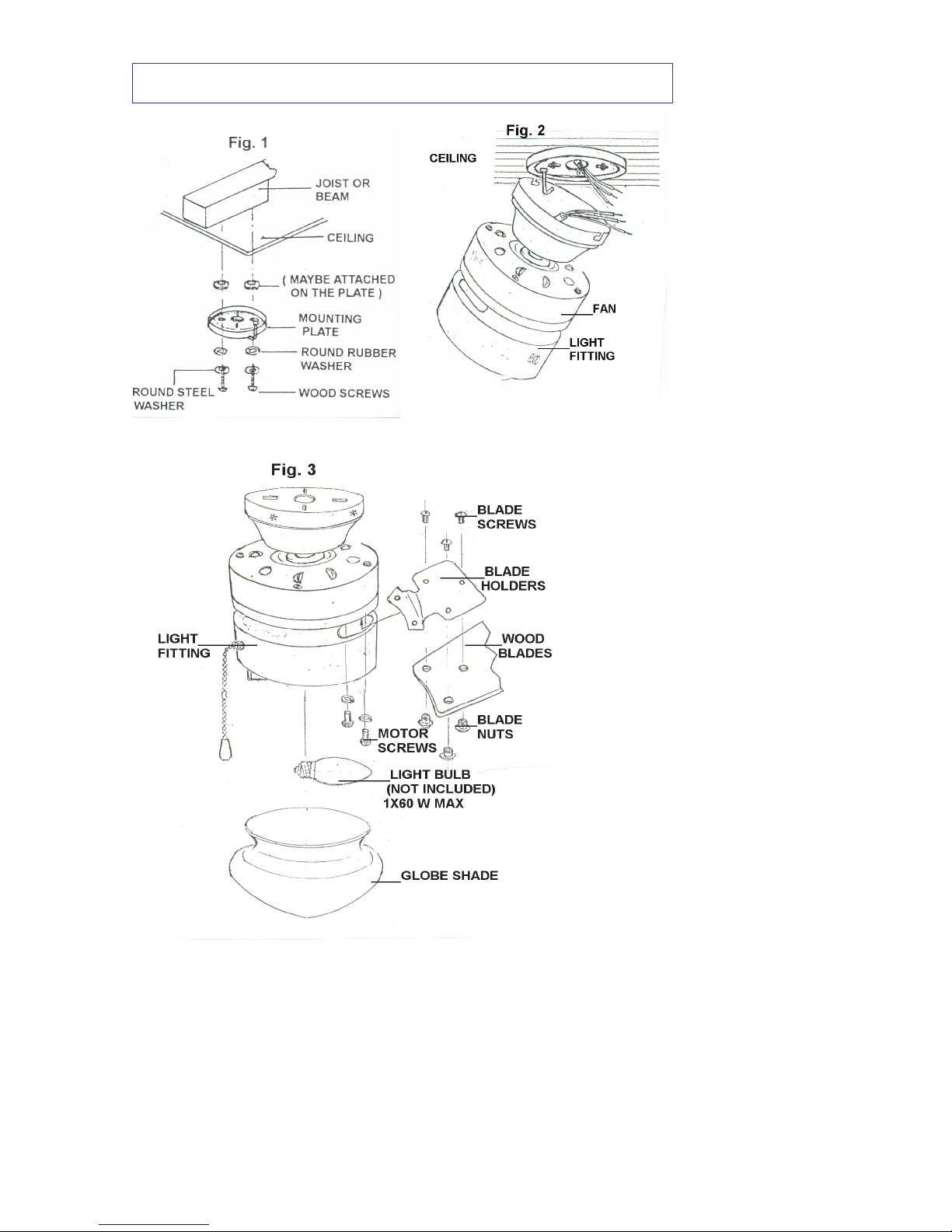
STEP 1: MOUNTING PLATE INSTALLATION
Loosen the screw of the mounting plate from canopy.
Secure the mounting plate to joist with wood screws, rubber and steel
washers. (See Fig. 1)/page 4.
CAUTION: Be sure that the mounting location can support load of
at 70 kilos. (see Safety Precautions)
STEP 2: HANGING
Hang the motor on mounting plate with temporary support (a hook)
(See Fig. 2)/page 4.
This is an aid in marking the electrical connection.
STEP 3 : WIRING (See Page 7)
CAUTION: Carefully read the WIRING INSTRUCTIONS and DIAGRAMS
Since improper installation may result in an electric short and
void the warranty
STEP 4 : FAN HANGING
Carefully push all wiring into canopy. Life off temporary
mount and position fan motor on mounting plate such that
attachment screws align with keyed slots on upper side of
motor housing secure the fan to mounting plate with serrated
washers and screws provided (See Fig. 3). Ensure a good
electrical connection by breaking lacquer finish as this forms
the earth.
STEP 5 : FAN ASSEMBLING
Turn on the electricity. Check to see that the fans forward and
reverse speeds work properly see operating instructions.
STEP 6: GLASS ASSEMBLING
The light fitting has been pre-assembled to your fan
(See Fig. 3) 60 watts max. Bulb (not provided) can be fitted. The
shade is held in place by three thumbscrews, do not over
tighten.
PAGE 6
FLUSH MOUNT STYLE ASSEMBLY DIAGRAMS
 Loading...