

Page 1

1
GAS FRYER
Installation and Operation Instructions
Models: T-CF15, T-CF30, T-CF15-L, T-CF30-L
IMPORTANT FOR FUTURE REFERENCE
Please complete this information and retain this manual for the life of the equipment. For
Warranty Service and/or parts, this information is required.
Model Number Serial Number Date Purchased
WARNING: For your safety, do not store or use gasoline or other flammable
vapours or liquids in the vicinity of this or any other appliances. Keep the area
free and clear of combustible. (See ANSI Z83. 14B, 1991).
WARNING: Improper installation, adjustment, alteration, service, or maintenance
can cause property damage, injury, or death. Read the installation operating and
maintenance instructions thoroughly before installing or servicing this equipment.
WARNING: Instructions must be posted in a prominent location. All safety
precautions must be taken in the event the user smells gas. Safety information
can be obtained from your local gas supplier.
CAUTION: These models are designed, built, and sold for commercial use only. If
these models are positioned so the general public can use the equipment, make sure
that cautions, warnings, and operating instructions are clearly posted near each unit so
that anyone using the equipment will use it correctly and not injure themselves or
damage the equipment.
GAS PRESSURE
The appliance and its individual shutoff valve (to be supplied by the user) must be
disconnected from the gas supply piping system during any pressure testing of that system
at test pressures in excess of ½ psi (3.45 kPa).
The appliance must be isolated from the gas supply piping system by closing its individual
manual shutoff valve during any pressure testing of the gas supply piping system at test
pressures equal to or less than ½ psi (3.45 kPa).
WARNING: A factory-authorized agent should handle all maintenance and repairs. Before
doing any maintenance or repairs, contact your authorized service
Page 2

2
TABLE OF CONTENTS
Congratulations on your purchase of Eurodib commercial cooking equipment. Eurodib takes
pride in the design and quality of our products. When used as intended and with proper care
and maintenance, you will experience years of reliable operation from this equipment. To
ensure best results, it is important that you read and follow the instructions in this manual
carefully.
LOCATION OF DATA PLATE
The data plate is located on the side panel.
IMMEDIATELY INSPECT FOR SHIPPING DAMAGE
All containers should be examined for damage before and during unloading. The freight
carrier has assumed responsibility for its safe transit and delivery. If equipment is received
damaged, either apparent or concealed, a claim must be made with the delivering carrier.
A. Apparent damage or loss must be noted on the freight bill at the time of delivery. It
must then be signed by the carrier representative (Driver). If this is not done, the
carrier may refuse the claim. The carrier can supply the necessary forms.
B. Concealed damage or loss if not apparent until after equipment is uncrated, a request
for inspection must be made to the carrier within 15 days. The carrier should arrange
an inspection. Be certain to hold all contents and packaging material.
A qualified installer who thoroughly read, understands and follows these instructions should
perform installation and maintenance.
If you have questions concerning the installation, operation, maintenance, or service of this
product, write to Eurodib.
ITEM
PAGE
ITEM
PAGE
Safety precautions
4
Troubleshooting
11
General Installation Instructions
5
Explosion View Drawing
12
Specifications & Dimensions
6
Spare Part List
13
Lighting Instructions
7
Operating Instructions
8
Cleaning & Maintenance
9
Page 3
3
SAFETY PRECAUTIONS
DANGER: This symbol warns of imminent hazard, which could result in serious
injury or death.
WARNING: This symbol refers to a potential hazard or unsafe practice, which
could result in serious injury or death.
CAUTION: This symbol refers to a potential hazard or unsafe practice, which
could result in minor or moderate injury or product or property damage.
NOTICE: This symbol refers to information that needs special attention or must be
fully understood even though not dangerous.
NOTICE: This product is intended for commercial use only. Not for household use.
NOTICE: Local codes regarding installation vary greatly from one area to another. The
National Fire Protection Association, Inc., states in its NFPA96 latest edition that
local codes are “Authority Having Jurisdiction” when it comes to requirement for
the installation of equipment. Therefore, the installation should comply with all local
codes.
Page 4

4
GENERAL INSTALLATION INSTRUCTIONS
Ensure that the gas supply and gas type, as shown on unit nameplate, agree.
Unit installation must conform with the National Fuel Gas Code, ANSI Z223.1/NFPA 54, the
National Gas Installation Code, CSA-B149.1, or the Propane Installation Code, CSA-B149.2
as applicable and in accordance with local codes.
Screw the legs into the permanently fastened nuts on the four corners of the unit and tighten
by hand. Level the unit by turning the adjustment screw at the bottom of each leg. Do not
slide the unit with legs mounted, lift if necessary to move unit.
Pipe threading compound must be resistant to the action of liquefied petroleum gases.
CAUTION: DO NOT use an open flame to check for leaks. Check all the gas piping for leaks
with a soap-and-water solution before operating the unit.
THESE UNITS ARE SUITABLE FOR INSTALLATION ON NON-COMBUSTIBLE
SURFACES ONLY.
Combustible clearances:
6" sides (152 mm) 6" rear (152 mm) 4" floor (102 mm)
Non-combustible clearances:
0" sides (0 mm) 0" rear (0 mm) 4" floor (102 mm)
Do not obstruct the flow of combustion and ventilation air, under the unit by the legs or
behind the unit by the flue. Adequate clearance for air openings into the combustion
chamber is required. Do not place objects between the bottom of the unit and the counter top.
There must be adequate clearance for removal of the front panel. All major parts, except the
burners, are removable through the front if the gas line is disconnected.
Page 5
5
SPECIFICATION AND DIMENSIONS
MODEL
WIDTH
IN.
DEPTH
IN.
HEIGHT
IN.
TOTAL
INPUT
(BTU)
INPUT GAS
PRESSURE
IN.W.C
WORKING
PRESSURE
IN.W.C
T-CF15
11
29-1/4
24-7/8
26,000 6 4
T-CF15-L
11
29-1/4
24-7/8
26,000
10
10
T-CF30
17-3/8
29-1/4
24-7/8
53,000 6 4
T-CF30-L
17-3/8
29-1/4
24-7/8
53,000
10
10
Note: Do not include the size of the regulator.
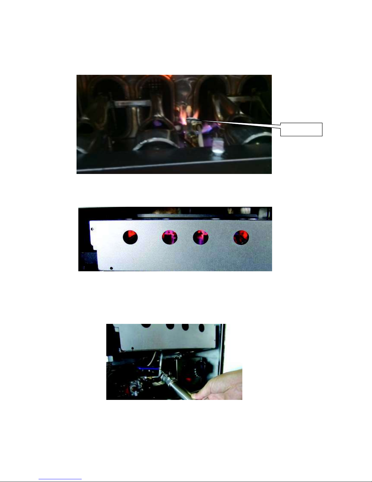
LIGHTING INSTRUCTIONS
(Model: T-CF30 with pilot Ignition)
Fryers are furnished with a gas control safety valve. Please follow the instructions below.
Before Lighting the Pilot and Burners
Fill the fat tank about 3/4" below the full line with proper frying compound before lighting the
pilot. The reason for
filling the tank 3/4" below the full line is that the frying compound will
expand during the preheating process.
If the frying compound expands above the full line, the frying compound may overflow out of
the tank during the cooking process. The reason for adding frying compound in the fry tank
before lighting the pilot or burners is that the unit will be damaged if this is not done.
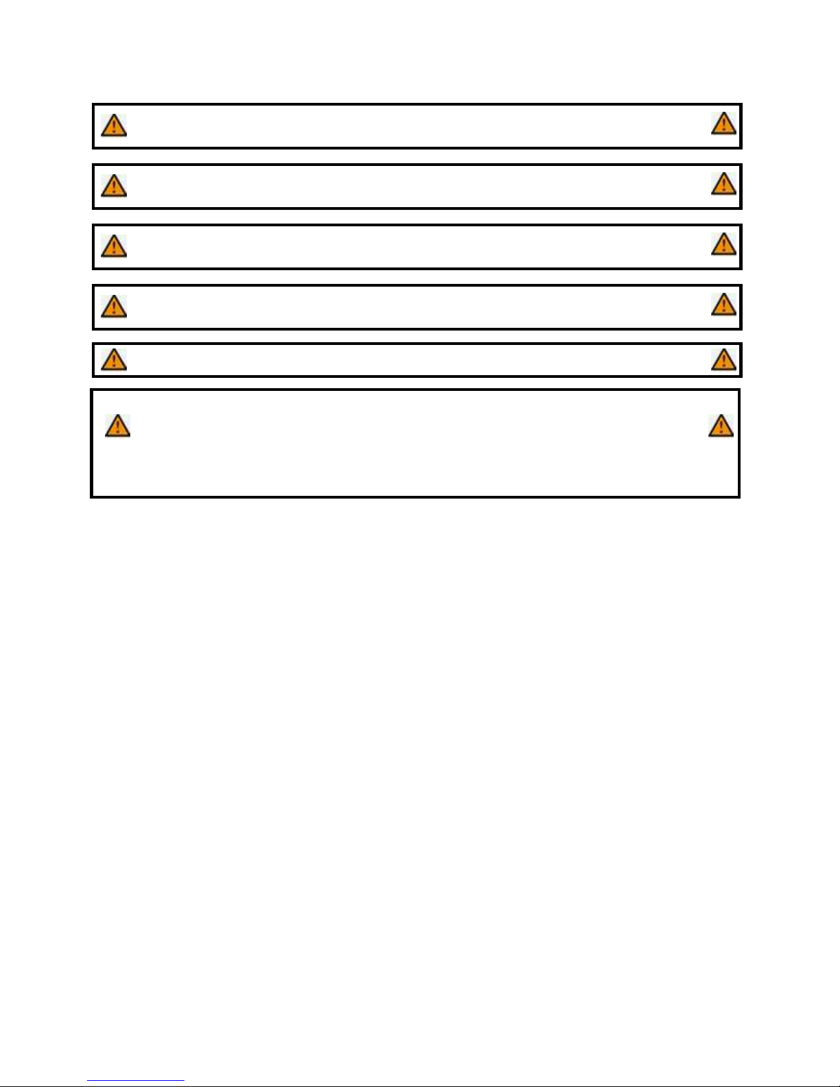
1.
Ensure this Gas Control Valve dial
is at the “OFF” position.
2. Ensure this thermostat dial is at the “OFF” position.
T-CF30 T-CF15
Page 6
6
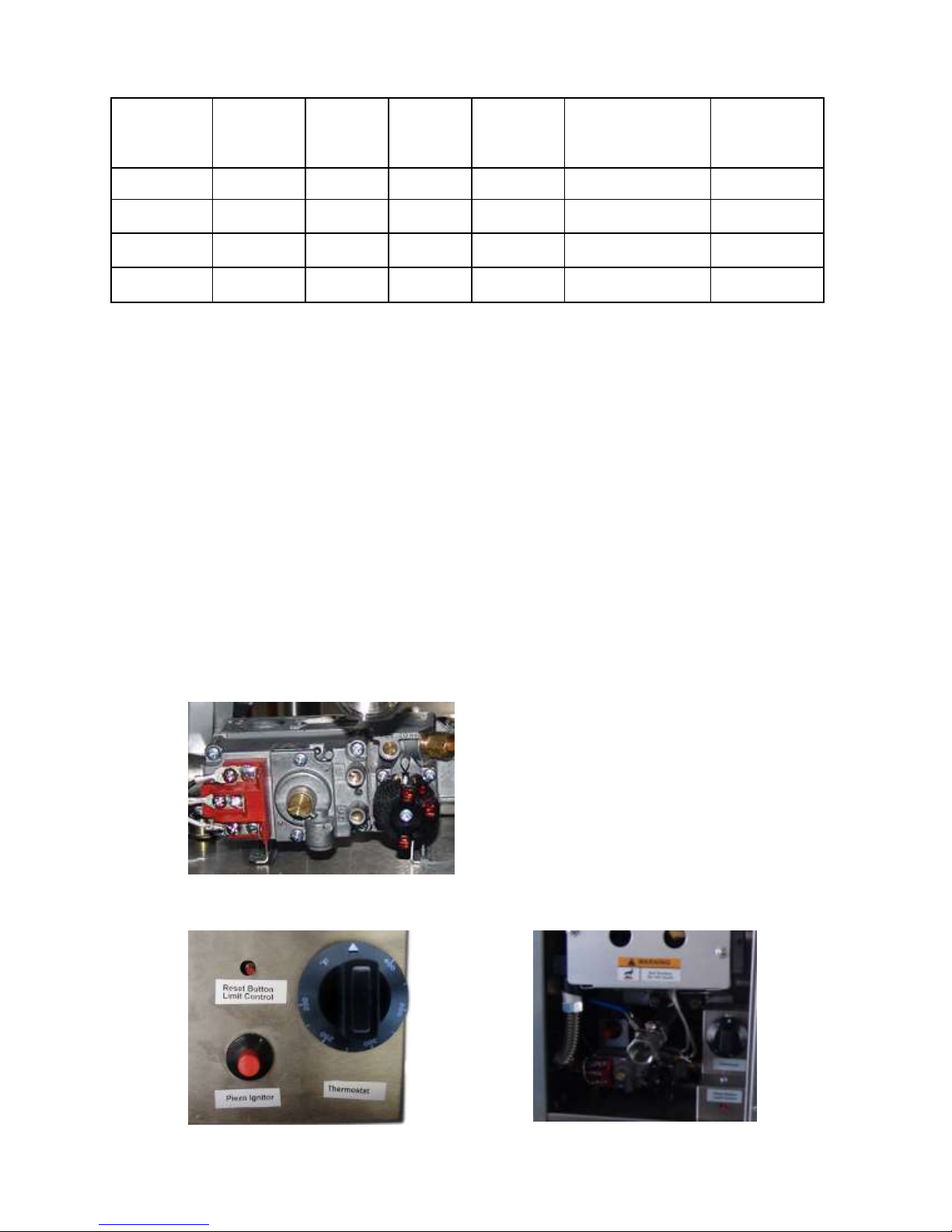
3.
Turn the gas control valve dial to “Pilot “ position and hold.
4.
Press the pilot ignition button. In order to
drain any air within the gas pipe system, for
the first use, please hold the valve dial at the “Pilot” position for 5-7 Minute till lighting.
Note: If the gas fryer is setting without the pilot ignition, please hold an ignition source (a
match) at the pilot. When the flame is established, remove the ignition source.
5.
Turn
the gas control valve dial to the “ON “ position and using the thermostat dial,
set the desired temperature. You can monitor the flame status through this panel.
Draining the Oil
A drain extension pipe attached to the inside of the main door has been provided.
Screw the drain extension pipe into the main drain valve. Once secured, use the blue handle
to turn the valve ON to release the oil.
Pilot Flame
Page 7

7
OPERATING INSTRUCTIONS
All burners are lit from constantly burning pilots. Turning the thermostat to the desired
temperature is all that is required to put the unit in service.
Do not permit fans to blow directly at the unit. Wherever possible, avoid open windows next
to the unit's sides or back. Avoid wall type fans which create air cross-currents within a room.
It is also necessary that sufficient air should be allowed to enter the room to compensate for
the amount of air removed by any ventilating system. Otherwise, a subnormal atmospheric
pressure will occur, which will affect the operation and cause undesirable working conditions.
A properly designed and installed hood will act as the heart of the ventilating system for the
room or area in which the unit is installed and will leave the unit independent of changing
draft conditions.
All the valves and thermostats must be checked periodically. Consult the authorized service
representative in your area.
CLEANING
Initial Cleaning
Always clean equipment thoroughly before the first use. Clean the protective oil from the
bright parts and interior of tank with a solution of washing soda or other grease dissolving
material.
Daily Cleaning
1. Always turn the unit OFF and allow it to cool off completely before cleaning.
2. Never clean the unit by immersing it in water.
3. The frequency of cleaning should depend on the load conditions. Set a definite
cleaning schedule corresponding to how hard the kettle is used. Cleaning should be
done at a least once a week.
4. Strain the frying compound into a clean container. Make sure there is no compound
left in the tank. (If the tank is left empty for more than 2 minutes, shut the pilot OFF. If
this is not done, the tank may be damaged.).
5. Add water to the "MAX" line.
6. Add any good grade cleaner following the cleaner’s instructions.
7. Turn the thermostat to 75°F (dial “°F” position). Let the heating unit bring the solution
to a boil.
8. Boil long enough to loosen or dissolve all varnish or carbon deposits. This should take
approximately 30 minutes.
9. Turn the unit OFF. Make sure the pilot is turned OFF at this time.
10. If necessary, clean the thermostat probes using a long-handled fibre or plastic brush
and mild soap solution.
11. Rinse with clean water to remove all cleaning mixture.
12. Rinse the inside of the tank with 2 cups of vinegar.
13. Rinse with clean water until the vinegar odour is gone. The fry tank must be
thoroughly rinsed since even a trace of cleaner left inside the tank will contaminate
the fry compound.
14. Dry thoroughly.
Page 8
8
15. Cover the tank if compound will not be added until a future date.
16. Clean all the exterior surfaces of the unit on a regular basis with a damp cloth. Thin
films of oil subjected to frying temperatures quickly form into gummy consistency. In
order to avoid these gum formations, clean the surfaces on a regular basis.
17. To remove discolorations or oil film, a non-abrasive cleaner may be used.
CAUTION: Clean the regulator at least once a month. Make sure the vent opening
is open and not blocked in any way. Failure to do so will cause variations in
pressure. Your unit will not function as well and it could shorten the life of the
product.
MAINTENANCE
Overnight Shutdown
Turn the temperature control knob to the OFF position. Or turn the OFF/PILOT/ON valve
control to PILOT if you wish not to change the temperature setting. (The pilot flame alone will
keep the frying compound temperature to 130-145°F(54.5-62.8℃). when not under any load.
This will shorten preheat time when turned back ON.)
Extended Shutdown (4 Days or Longer)
1. Turn the temperature control knob to the OFF position.
2. Turn the OFF/PILOT/ON valve control knob to the OFF position.
3. Turn the manual control valve under the unit to the OFF position.
4. Turn the supply valve to the OFF position (not supplied by Thor).
5. The entire flue duct opening on the top rear of unit must always be left uncovered.
Filling Fry Tank
CAUTION: Never lit the pilot or turn the burners ON with an empty tank
1. Fill the fry tank approximately 3/4" below the full line. The fry compound will expand
as it is heated. Heat the fry compound to 375° F(190℃) for 20 minutes then check the
level. Add or decrease the amount of fry compound so it lines up with the full line.
2. When using solid frying compound, put enough compound in the fry tank so at least
half or more of the tank contains compound. Then set the temperature to 200°F
(93.3℃) on the dial and allow the compound to liquefy. Add to adjust the compound
level.
3. Use a quality frying compound.
4. Filter the frying compound frequently, at least once a day.
5. Skim out food particles frequently with a strainer/skimmer.
6. Add at least 15% (fry tank capacity) of fresh frying compound daily (more if possible)
without overloading the tank. If 15% of frying compound is not used daily, remove
some of the compound for other use (gravy, griddle frying, etc.) to permit adding 15%
of fresh compound daily.
7. Do not overload the fry baskets. This will result in longer recovery time, longer cook
time, and compound absorption into the product.
8. Prepare the food properly.
Page 9

9
9. Keep salt out of the frying compound. Do not salt foods with the basket above the
kettle.
10. Ensure a good thermostat operation by checking the frying compound temperature
with a reliable frying thermometer. Compound temperature should be comparable to
the thermostat setting.
11. Keep the fry tank and thermo-probes clean.
Thermostat Calibration
The fryer control is factory calibrated. If cooking results indicate unit is not maintaining
correct temperatures, consult an authorized service representative.
SERVICE / REPAIR
NOTE: This appliance must only be serviced by an authorized agent.
NOTE: Parts protected by the manufacturer or his agent are not to be adjusted by the
installer, unless the installer is an authorized service agent.
If you have any questions or problems, contact your nearest EURODIB Service
Representative.
Page 10

10
TROUBLESHOOTING GUIDE
PROBLEM
POSSIBLE CAUSE
Frying temperature too
high/overheating (check thermostat)
Frying temperature too
low/overheating (check thermostat)
Over loading fryer
Improper draining of food after
frying
High moisture content in food being
fried
Inadequate frying compound
turnover
Improper preparation of food
Contamination of fryer compound
(due to salt or other foreign
material)
Excessive & premature foaming
★ ★
★
★
Greasy food / excessive frying compound
absorption
★ ★ ★ ★ ★
★
Objectionable odour or flavour of frying
compound
★ ★
★
Objectionable flavour of fried food
★
★
★
Excessive smoking of frying compound
★
★ ★ ★
Excessive darkening of frying compound
★
★ ★ ★
Frying compound won’t hold heat
★
★ ★ ★
Food crust color not brown
★
★ ★ ★
Rapid breakdown of frying compound
★
★
★
★
Page 11

11
EXPLOSION VIEW DRAWING
MODELS: T-CF15 / T-CF15-L
Page 12

12
Spare Parts List
NO.
DESCRIPTION
MODEL
CODE
QTY
1
Adjustable stainless steel feet
T-CF15 / T-CF15-L
T-CF30 / T-CF30-L
01.02.1005165
4 2 Door hinge
T-CF15 / T-CF15-L
T-CF30 / T-CF30-L
06.05.1471050
1
3
Support plate for front feet
T-CF15 / T-CF15-L
01.05.1026492
1
T-CF30 / T-CF30-L
01.05.1026745
4
Thermostat enclosure
T-CF15 / T-CF15-L
01.05.1026471
1
T-CF30 / T-CF30-L
06.05.1472708
5
LCHM limit control
T-CF15 / T-CF15-L
T-CF30 / T-CF30-L
03.99.1290101
1
6
Thermostat, millivolt
T-CF15 / T-CF15-L
T-CF30 / T-CF30-L
03.05.1220047
1
7
Supporting plate for rear feet
T-CF15 / T-CF15-L
01.05.1026493
1
T-CF30 / T-CF30-L
01.05.1026746
8
REGULATOR 6"-NAT
or10"-LP ,3/4"-NPT
T-CF15 / T-CF15-L
T-CF30 / T-CF30-L
01.22.1069501
1 9 Panel, right
T-CF15 / T-CF15-L
T-CF30 / T-CF30-L
01.05.1026491
1
10
Right plate of flue
T-CF15 / T-CF15-L
T-CF30 / T-CF30-L
01.05.1026496
1
11
Rear panel
T-CF15 / T-CF15-L
01.05.1026498
1
T-CF30 / T-CF30-L
01.05.1026753
12
Basket pothook
T-CF15 / T-CF15-L
01.10.1061012
1
T-CF30 / T-CF30-L
01.10.1061008
13
Front plate of flue
T-CF15 / T-CF15-L
01.15.1066125
1
T-CF30 / T-CF30-L
01.15.1066131
14
Rear plate of flue
T-CF15 / T-CF15-L
01.05.1026497
1
T-CF30 / T-CF30-L
01.05.1026752
15
Fryer tank assy.
T-CF15 / T-CF15-L
06.05.1472648
1
T-CF30 / T-CF30-L
06.05.1472672
16
Filter panel
T-CF15 / T-CF15-L
01.05.1026472
1
T-CF30 / T-CF30-L
01.05.1026751
17
Basket baffle
T-CF15 / T-CF15-L
01.10.1061014
1
T-CF30 / T-CF30-L
01.10.1061010
18
Basket
T-CF15 / T-CF15-L
01.02.1005190
1
T-CF30 / T-CF30-L
2
19
Left plate of flue
T-CF15 / T-CF15-L
T-CF30 / T-CF30-L
01.05.1026495
1
20
Panel, left
T-CF15 / T-CF15-L
T-CF30 / T-CF30-L
01.05.1026490
1
21
Valve, tank drain
T-CF15 / T-CF15-L
T-CF30 / T-CF30-L
06.05.1472578
1
Page 13

13
22
Tank drain pipe
T-CF15 / T-CF15-L
T-CF30 / T-CF30-L
01.02.1005436
1
23
Isolating plate, upper of burner
T-CF15 / T-CF15-L
01.15.1066117
1
T-CF30 / T-CF30-L
01.15.1066061
24
ODS flame protection
T-CF15 / T-CF30
01.21.1069001
1
T-CF15-L / T-CF30-L
01.21.1069003
25
Burner assy.
T-CF15 / T-CF15-L
06.05.1470489
2
T-CF30 / T-CF30-L
4
26
Orifice 51#
T-CF15 / T-CF30
01.20.1068651
2
Orifice 58#
T-CF15-L / T-CF30-L
01.20.1068658
4
27
Gas pipe assy.
T-CF15 / T-CF15-L
01.24.1070584
1
T-CF30 / T-CF30-L
01.24.1070583
28
Isolating plate, front
T-CF15 / T-CF15-L
01.15.1066123
1
T-CF30 / T-CF30-L
01.15.1066129
29
Door assy.
T-CF15 / T-CF15-L
06.05.1472706
1
T-CF30 / T-CF30-L
06.05.1472705
30
Door handle assy.
T-CF15 / T-CF15-L
T-CF30 / T-CF30-L
06.05.1472707
1
31
Isolating plate, lower of burner
T-CF15 / T-CF15-L
01.15.1066118
1
T-CF30 / T-CF30-L
01.15.1066024
32
Corrugated pipe
T-CF15 / T-CF15-L
T-CF30 / T-CF30-L
01.02.1005117
1
33
Piezo ignition
T-CF15 / T-CF15-L
T-CF30 / T-CF30-L
03.99.1290152
1
34
Safety control valve assy.
T-CF15 / T-CF30
06.05.1470654
1
T-CF15-L / T-CF30-L
06.05.1470674
35
Pilot pipe assy.
T-CF15 / T-CF15-L
06.05.1472602
1
T-CF30 / T-CF30-L
06.05.1472603
36
Thermopile
T-CF15 / T-CF15-L
T-CF30 / T-CF30-L
03.11.1250027
1
Note: Use T-CF15, T-CF30 for natural gas and T-CF15-L, T-CF30-L for propane.
For service or Inquiry, please
Call Eurodib (Toll free) at:
1 888 956 6866
Page 14

14
Limited Warranty
Eurodib Cooking Equipment Models:
Griddles: T-G15, T-G24, T-G36, T-G48
Char Broilers: T-CBL15, T-CBL24, T-CBL36, T-CBL48, T-CBR15, T-CBR24,
T-CBR36, T-CBR48
Coutertop Range: T-HP212, T-HP424, T-HP636
Fryer: T-CF15, T-CF30
All new Eurodib griddles, char broilers, fryers and countertop range used for commercial
purposes are warranted against defects in materials and workmanship under normal use
and maintenance. The warranty runs for one year from the date of the original installation
and is for the benefit of the original purchaser only. All other warranties, expressed or implied,
statutory or otherwise, including without limitation any implied warranty of merchantability for
fitness for purposes, are excluded. The seller shall in no event be liable for direct, indirect, or
consequential damages in connection with Eurodib commercial products.
Exclusions
The following conditions are not covered by warranty:
Equipment damage or equipment failure occurs because of accident, carelessness,
lack of proper set-up, supervision when required, or if the equipment is installed or
operated in any manner contrary to the installation and operating instructions.
Equipment damage or equipment failure due to improper installation, improper utility
connection or supply, and problems due to ventilation.
Equipment that has not been used appropriately, or has been subject to misuse,
neglect, abuse, accident, alteration, negligence, damage during transit, delivery or
installation, fire, flood, or act of God.
Equipment that has the model number or serial number removed or altered.
Equipment that has been changed, altered, or modified or repaired by other than an
Authorized Service Agency.
Eurodib shall not be held liable for any damages to any person or property, which may result
from the use of the equipment thereafter.
This warranty does not apply to, and Eurodib is not responsible for any warranty claims on
products sold or used outside of the contiguous United States.
This equipment is intended for commercial use only. The warranty is void if equipment is
installed for other than commercial applications.
Page 15

15
FRITEUSE À GAZ
Instructions d'installation et d'utilisation
Modèles : T-CF15, T-CF30, T-CF15-L, T-CF30-L
IMPORTANT
POUR CONSULTATION FUTURE
Prière de fournir ces renseignements et de conserver ce manuel pendant toute la durée de
vie de l'appareil. Pour le service ou les pièces sous garantie, ces renseignements sont
requis.
Numéro de modèle Numéro de série Date de l'achat
AVERTISSEMENT : Pour votre sécurité, ne jamais ranger ni utiliser d'essence, ou
d'autres vapeurs ou liquides inflammables, à proximité de cet appareil ou de tout
autre appareil. Tenir les matières combustibles loin de la zone. (voir la norme
ANSI Z83. 14B, 1991).
AVERTISSEMENT : Toute installation, modification, réparation, tout réglage ou
entretien inapproprié peut occasionner des dommages matériels, des blessures
graves ou la mort. Lire les instructions d'installation, d'utilisation et d'entretien
attentivement avant d'installer ou de réparer cet appareil.
AVERTISSEMENT : Les instructions doivent être affichées dans un endroit bien en
vue. Toutes les mesures de sécurité doivent être prises dans l'éventualité où
l'utilisateur détecte une odeur de gaz. L'information de sécurité peut être obtenue
auprès de votre fournisseur de gaz local.
ATTENTION : Ces modèles sont conçus, fabriqués et vendus pour un usage
commercial seulement. Si ces modèles sont mis à la disposition du grand public,
s'assurer que les mises en garde, les avertissements et les instructions
d'utilisation sont clairement affichés, près de chaque appareil, de sorte que tout
utilisateur de l'appareil l'utilise correctement et ne se blesse pas ou n'endommage pas
l'appareil.
AVERTISSEMENT : Les instructions doivent être affichées dans un endroit bien
en vue. Toutes les mesures de sécurité doivent être prises dans l'éventualité où
l'utilisateur détecte une odeur de gaz. L'information de sécurité peut être obtenue
auprès de votre fournisseur de gaz local.
Page 16

16
PRESSION DE GAZ
L'appareil et sa vanne d'arrêt individuelle (à être fournie par l'utilisateur) doivent être
débranchés de la canalisation d'approvisionnement en gaz durant toute pression d'essai du
système dont la pression d'essai est égale ou supérieure à 0,5 psi (3,45 kPa).
L'appareil doit être isolé du système de canalisation d'alimentation en gaz par la fermeture
de la vanne d'arrêt manuelle individuelle durant toute pression d'essai du système de
canalisation d'approvisionnement en gaz dont la pression d'essai est égale ou inférieure à
0,5 psi (3,45 kPa).
AVERTISSEMENT : L'entretien et les réparations devraient être effectués par un
représentant autorisé par l'usine. Avant de procéder à tout entretien ou réparation,
contactez votre représentant du service autorisé.
Page 17

17
TABLE DES MATIÈRES
Félicitations pour l'achat de votre appareil de cuisson commercial Eurodib. Eurodib est fière
de la conception et de la qualité de ses produits. Cet appareil vous procurera une fiabilité
d'utilisation pendant de nombreuses années, à condition de l'utiliser comme prévu, d'en
prendre bien soin et d'en faire l'entretien. Pour obtenir de meilleurs résultats, il est important
de bien lire et suivre les instructions dans ce manuel.
EMPLACEMENT DE LA PLAQUE SIGNALÉTIQUE
La plaque signalétique est située sur le panneau latéral.
VÉRIFIER IMMÉDIATEMENT S'IL Y A DOMMAGES DUS AU TRANSPORT
Tous les contenants devraient être examinés pour déceler des dommages avant et pendant
le déchargement. Le transporteur de marchandises a assumé la responsabilité du transit et
de la livraison indemnes. Dans l'éventualité où l'appareil livré est endommagé (apparent ou
caché), une réclamation doit être effectuée avec le transporteur de marchandises.
A) Un dommage apparent ou une perte doit être indiqué sur la facture de transport au
moment de la livraison. Celle-ci doit être ensuite signée par le représentant du transporteur
(le chauffeur). À défaut de quoi le transporteur peut refuser la réclamation. Le transporteur
peut fournir les formulaires requis.
B) Un dommage caché ou une perte qui n'était pas apparent jusqu'au moment de déballer
l'appareil doit faire l'objet d'une requête d'inspection à soumettre au transporteur dans un
délai de 15 jours. Le transporteur devrait organiser une inspection. Assurez-vous de
conserver tout le contenu et le matériel d'emballage.
L'installation et l'entretien devraient être effectués par un installateur qualifié qui a lu,
comprend et suit attentivement ces instructions.
Si vous avez des questions au sujet de l'installation, de l'utilisation, de l'entretien ou du
service de ce produit, veuillez écrire à Eurodib.
ARTICLE
PAGE
ARTICLE
PAGE
Mesures de sécurité
4
Dépannage
11
Instructions d'installation générales
5
Vue éclatée
12
Spécifications et dimensions
6
Liste des pièces de rechange
13
Instructions d'allumage
7
Instructions d'utilisation
8
Nettoyage et entretien
9
Page 18

18
MESURES DE SÉCURITÉ
DANGER : Ce symbole signale un danger imminent pouvant entraîner des
blessures graves ou la mort.
AVERTISSEMENT : Ce symbole désigne un risque potentiel ou une pratique
dangereuse pouvant entraîner des blessures graves ou la mort.
ATTENTION : Ce symbole désigne un risque potentiel ou une pratique
dangereuse pouvant entraîner des blessures mineures ou modérées, ou des
dommages au produit ou à la propriété.
AVIS : Ce symbole désigne l'information nécessitant une attention particulière ou
devant être entièrement comprise, malgré l'absence de danger.
AVIS : Ce produit est destiné à un usage commercial seulement. Ce produit n'est
pas destiné à un usage domestique.
AVIS : Les normes locales concernant l'installation changent considérablement
d'un secteur à l'autre. National Fire Protection Association, Inc., déclare dans sa
dernière édition NFPA96 que les normes locales relèvent des « autorités
compétentes » en ce qui a trait aux conditions d'installation d’appareils. Par
conséquent, l'installation doit être conforme à toutes les normes locales.
INSTRUCTIONS D'INSTALLATION GÉNÉRALES
Assurez-vous que l'approvisionnement en gaz et le type de gaz concordent, comme
l'indique la plaque signalétique de l'appareil.
L'installation de l'appareil doit être conforme au National Fuel Gas Code, ANSI Z223.1/NFPA
54, au National Gas Installation Code, CSA-B149.1 ou au Propane Installation Code,
CSA-B149.2, selon le cas et conformément aux normes locales.
Visser les pattes dans les écrous fixes se trouvant aux quatre coins de l'appareil et serrer à
la main. Niveler l'appareil en tournant la vis de réglage au bas de chaque patte. Ne pas
glisser l'appareil avec les pattes fixées; soulever pour déplacer l'appareil au besoin.
Le composé pour filetage doit résister à l'action des gaz de pétrole liquéfiés.
ATTENTION : NE JAMAIS employer une flamme nue pour déceler des fuites. Examiner
toutes les conduites de gaz pour déceler des fuites avec une solution de savon et d'eau
avant d'utiliser l'appareil.
Page 19

19
CES APPAREILS DOIVENT ÊTRE INSTALLÉS UNIQUEMENT SUR DES SURFACES
NON COMBUSTIBLES.
Espaces de dégagement pour les matières combustibles :
6 po des côtés (152 mm) 6 po de l'arrière (152 mm) 4 po du sol (102 mm)
Espaces de dégagement pour les matières non combustibles :
0 po des côtés (0 mm) 0 po de l'arrière (0 mm) 4 po du sol (102 mm)
Ne pas obstruer le débit de l'air de combustion ou de ventilation sous l'appareil près des
pattes, ou derrière l'appareil près du conduit d'air.
Un espace de dégagement adéquat est requis pour les ouvertures d'aération dans la
chambre de combustion. Ne pas placer d'objets entre le bas de l'appareil et le plan de
travail.
Un espace de dégagement adéquat est requis pour retirer le panneau frontal. Toutes les
pièces principales (sauf les brûleurs) sont amovibles par la partie frontale si la conduite de
gaz est déconnectée.
SPÉCIFICATIONS ET DIMENSIONS
MODÈLE
LARGEUR
EN PO
PROFONDEUR
EN PO
HAUTEUR
EN PO
ENTRÉE
TOTAL
(BTU)
PRESSIO
N DE GAZ
INJECTÉ
DANS LA CE
PRESSION
D’UTILISATION
DANS LA CE
T-CF15
11
29-1/4
24-7/8
26 000 6 4
T-CF15-L
11
29-1/4
24-7/8
26 000
10
10
T-CF30
17-3/8
29-1/4
24-7/8
53 000 6 4
T-CF30-L
17-3/8
29-1/4
24-7/8
53 000
10
10
Remarque : Ne pas inclure la dimension du régulateur.
INSTRUCTIONS D'ALLUMAGE
(Modèle : T-CF30 avec allumage par veilleuse)
Les friteuses sont dotées d'une valve de sécurité pour le gaz. Veuillez suivre les instructions
ci-dessous.
Avant d'allumer la veilleuse d'allumage et les brûleurs
Remplir le réservoir à graisse avec le mélange à friture approprié, jusqu'à environ 3/4 po
sous la ligne de remplissage. Le remplissage du réservoir jusqu'à 3/4 po en dessous de la
ligne de remplissage est en raison de l'expansion que prend le mélange à friture au cours du
processus de préchauffage.
Si l'expansion du mélange à friture dépasse la ligne de remplissage, le mélange à friture
risque de déborder du réservoir au cours du processus de cuisson. L'ajout du mélange à
friture dans le réservoir à frire avant d'allumer la veilleuse d'allumage ou les brûleurs sert à
éviter d'endommager l'appareil.
Page 20

20
1. S'assurer que le cadran de la vanne de réglage du gaz
est à la position « OFF »
(éteint).
2.
S'assurer
que le cadran du thermostat est à la position « OFF » (éteint).
T-CF30 T-CF15
3.
Régler le cadran de la vanne de réglage du gaz à la position « Pilot » (veilleuse) et
maintenir enfoncé. Appuyer sur le bouton d'allumage de la veilleuse. Afin d'évacuer
l'air du système de canalisation de gaz (pour la première utilisation), veuillez maintenir
le cadran de la vanne enfoncé à la position « Pilot » (veilleuse) pendant 5 à 7 minutes
jusqu'à l'allumage.
Remarque : Pour allumer la friteuse à gaz sans l'allumage par veilleuse, veuillez tenir une
source d'inflammation (une allumette) à la veilleuse d'allumage. Une fois la flamme allumée,
retirer la source d'inflammation.
Veuilleuse
d'allumage
Page 21

21
4. Régler le
cadran
de la vanne de réglage du gaz à la position « ON » (allumé) et régler
à la température désirée à l'aide du cadran du thermostat. Vous pouvez surveiller l'état
de la flamme sur ce panneau
Instructions pour la vidange d'huile
Une rallonge est fournie pour la vidange d'huile, qui se trouve à l'intérieur de la porte
principale.
Visser la rallonge dans la vanne de vidange principale. Une fois en place, utiliser la poignée
bleue; tourner la valve pour vidanger l'huile.
Page 22

22
INSTRUCTIONS D'UTILISATION
Tous les brûleurs s'allument par des veilleuses constamment allumées. Pour mettre
l'appareil en marche, il suffit de régler le thermostat à la température désirée.
Ne pas permettre aux ventilateurs de souffler directement sur l'appareil. Dans la mesure du
possible, éviter d'ouvrir les fenêtres près des côtés ou de l'arrière des appareils. Éviter les
ventilateurs de type mural qui créent des contrecourants d'air dans la pièce. Il faut
également permettre une entrée d'air suffisante dans la pièce pour compenser la quantité
d'air éliminée par n'importe quel système de ventilation. Sinon, une pression atmosphérique
inférieure à la normale se produira, ce qui affectera le fonctionnement et entraînera des
conditions de travail indésirables.
Une hotte conçue et installée convenablement constituera le cœur du système de ventilation
de la pièce, ou du secteur dans lequel l'appareil est installé, et veillera à ce que l'appareil
fonctionne indépendamment de l'admission de l'air changeante.
Toutes les vannes doivent être vérifiées et lubrifiées périodiquement. Demandez conseil au
représentant de service autorisé de votre région.
NETTOYAGE
Premier nettoyage
Toujours nettoyer à fond l'appareil avant sa première utilisation. Nettoyer l'huile de protection
des pièces d'acier nues et l'intérieur du réservoir avec une eau de lessive de soude ou un
autre produit dégraissant.
Nettoyage quotidien
1. Toujours éteindre l'appareil et le laisser refroidir complètement avant de nettoyer.
2. Ne jamais nettoyer l'appareil en le plongeant dans l'eau.
3. La fréquence de nettoyage varie en fonction des conditions de charge. Établir un
horaire de nettoyage précis en fonction du niveau d'utilisation de la friteuse. Le
nettoyage devrait être effectué au moins une fois par semaine.
4. Verser le mélange à friture dans un récipient propre. S'assurer qu'il ne reste plus de
mélange dans le réservoir. (Si le réservoir reste vide pendant plus de deux minutes,
éteindre la veilleuse. À défaut de quoi le réservoir risque de s'endommager.)
5. Ajouter de l'eau jusqu'à la ligne « MAX ».
6. Ajouter un nettoyant de bonne qualité en suivant les instructions de nettoyage.
7. Régler le thermostat à 75°F (position du cadran à « °F »). Permettre à l'appareil de
chauffage de porter la solution à ébullition.
8. Faire bouillir suffisamment longtemps pour déloger ou dissoudre tous les dépôts de
vernis ou de carbone. Ceci devrait prendre environ 30 minutes.
9. Éteindre l'appareil. S'assurer que la veilleuse est éteinte à ce moment précis.
10. Nettoyer les sondes du thermostat au besoin, à l'aide d'une brosse de fibres ou en
plastique à long manche et d'une solution savonneuse douce.
11. Rincer avec de l'eau propre pour déloger tout mélange de nettoyage.
12. Rincer l'intérieur du réservoir avec deux tasses de vinaigre.
Page 23

23
13. Rincer avec de l'eau propre jusqu'à ce qu'il n'y ait plus d'odeur de vinaigre. Le
réservoir à frire doit être rincé à fond en raison du mélange à friture qui sera
contaminé par toute trace de nettoyant laissée à l'intérieur du réservoir.
14. Sécher complètement.
15. Recouvrir le réservoir si le mélange n'est ajouté qu'à une date ultérieure.
16. Nettoyer régulièrement toutes les surfaces extérieures de l'appareil avec un chiffon
humide. Les couches minces d'huile qui sont exposées à des températures de friture
formeront rapidement des dépôts gommeux. Afin de prévenir la formation de ces
dépôts gommeux, nettoyer régulièrement les surfaces.
17. Pour éliminer la décoloration ou les couches d'huile, un nettoyant non abrasif peut
être utilisé.
ATTENTION : Nettoyer le régulateur au moins une fois par mois. Assurez-vous
que l'orifice de ventilation est ouvert et libre de toute obstruction. Le non-respect
de cette précaution entraînera des variations de pression. Votre appareil ne
fonctionnera pas comme il se doit et sa durée de vie risque d'être écourtée.
Page 24

24
ENTRETIEN
Arrêt de nuit
Régler le bouton de température à la position off (éteint). Si vous ne souhaitez pas changer
le réglage de la température, tourner le bouton de commande de la vanne Off/Pilot/On à
« Pilot » (veilleuse). (La flamme de la veilleuse maintiendra la température du mélange à
friture entre 130 et 145°C (54,5 et 62,8°F) lorsqu'elle n'a aucune charge. Ceci écourtera la
durée de préchauffage lors du rallumage.)
Arrête prolongé (4 jours ou plus)
1. Régler le bouton de température à la position off (éteint).
2. Tourner bouton de commande de la vanne Off/Pilot/On à « Pilot » (veilleuse).
3. Tourner la vanne de commande manuelle sous l'appareil à la position off (éteint).
4. Tourner la vanne d'alimentation à la position off (éteint) (non fournie par Thor).
5. L'ouverture du conduit de fumée, située en haut à l'arrière de l'appareil, doit toujours être
laissée à découvert.
Remplissage du réservoir à frire
ATTENTION : Ne jamais allumer la veilleuse ou les brûleurs avec un réservoir vide.
1. Remplir le réservoir à frire jusqu'à environ 3/4 po en dessous de la ligne de
remplissage. Le mélange à friture prendra de l'expansion à mesure d'être chauffé.
Faire chauffer le mélange à friture à 375°F (190℃) pendant 20 minutes et ensuite,
vérifier le niveau. Ajouter ou réduire la quantité de mélange à friture de sorte à
s'aligner avec la ligne de remplissage.
2. Pour l'utilisation d'un mélange à friture solide, s'assurer de remplir le réservoir à friture
avec le mélange au moins à moitié. Ensuite, régler la température du cadran à 200°F
(93,3°C) et laisser le mélange se liquéfier. Ajouter pour ajuster le niveau du mélange.
3. Utiliser un mélange à friture de qualité.
4. Filtrer le mélange à friture fréquemment, au moins une fois par jour.
5. Écumer les particules d'aliments fréquemment à l'aide d'un tamis/écumoire.
6. Ajouter quotidiennement au moins 15 % (de la capacité du réservoir à frire) de
nouveau mélange à friture (plus si possible) sans surcharger le réservoir. Si 15 % du
mélange à friture ne sont pas utilisés quotidiennement, retirer un peu de mélange
pour en faire un autre usage (sauce, friture sur le grilloir, etc.) afin de pouvoir ajouter
quotidiennement 15 % de nouveau mélange.
7. Ne pas surcharger les paniers à friture. Ceci entraînera le prolongement du temps de
récupération et du temps de cuisson, et l'absorption du mélange par le produit.
8. Préparer les aliments correctement.
9. Tenir le sel loin du mélange à friture. Ne pas saler les aliments dans le panier,
au-dessus de la friteuse.
10. S'assurer du bon fonctionnement du thermostat en vérifiant la température du
mélange à friture, à l'aide d'un thermomètre à friture fiable. La température du
mélange devrait être comparable au réglage du thermostat.
11. Garder le réservoir à frire et les thermosondes propres.
Page 25

25
Étalonnage du thermostat
L'étalonnage des commandes de la friteuse est effectué en usine. Si les résultats de cuisson
indiquent que l'appareil ne maintient pas les bonnes températures, demander conseil à un
représentant de service autorisé.
SERVICE/RÉPARATION
REMARQUE : L'entretien de cet appareil doit être effectué uniquement par un représentant
autorisé.
REMARQUE : Les pièces protégées par le fabricant ou son représentant ne doivent pas être
ajustées par l'installateur, à moins que ce dernier ne soit un représentant de service autorisé.
Si vous avez des questions ou des problèmes, veuillez communiquer avec le
représentant de service EURODIB de votre région.
GUIDE DE DÉPANNAGE
PROBLÈME
CAUSE POSSIBLE
La température de friture est trop
élevée/surchauffe (vérifier le
thermostat)
La température de friture est trop
basse/surchauffe (vérifier le
thermostat)
La friteuse est surchargée
Les aliments ne sont pas égouttés
convenablement après leur friture
Le taux d'humidité de l'aliment frit
est trop élevé
Rotation inappropriée du mélange à
friture
Préparation inappropriée des
aliments
Contamination du mélange à friture
(en raison du sel ou d'un autre
corps étranger)
Formation de mousse excessive et
prématurée
★
★
★
★
Aliments gras / absorption excessive de
mélange à friture
★ ★ ★ ★ ★
★
Odeur ou saveur indésirable du mélange à
friture
★
★ ★
Saveur indésirable des aliments frits
★
★
★
Fumée excessive du mélange à friture
★
★ ★ ★
Brunissement excessif du mélange à
friture
★
★ ★ ★
Le mélange à friture ne maintient pas sa
chaleur
★
★ ★ ★
La croûte de l'aliment n'est pas dorée
★
★ ★ ★
Détérioration rapide du mélange à friture
★
★
★
★
Page 26

26
VUE ÉCLATÉE
MODÈLES : T-CF15-L, T-CF15-L
Page 27

27
Liste des pièces de rechange
NUMÉRO
DESCRIPTION
MODÈLE
CODE
QTÉ
1
Pattes ajustables en acier inoxydable
T-CF15-L / T-CF15-L
T-CF30-L / T-CF30-L
01.02.1005165
4 2 Charnière de porte
T-CF15-L / T-CF15-L
T-CF30-L / T-CF30-L
06.05.1471050
1
3
Plaque de support pour pattes avant
T-CF15-L / T-CF15-L
01.05.1026492
1
T-CF30-L / T-CF30-L
01.05.1026745
4
Boîtier de thermostat
T-CF15-L / T-CF15-L
01.05.1026471
1
T-CF30-L / T-CF30-L
06.05.1472708
5
Limiteur lchm
T-CF15-L / T-CF15-L
T-CF30-L / T-CF30-L
03.99.1290101
1
6
Thermostat, millivolt
T-CF15-L / T-CF15-L
T-CF30-L / T-CF30-L
03.05.1220047
1
7
Plaque de support pour pattes arrière
T-CF15-L / T-CF15-L
01.05.1026493
1
T-CF30-L / T-CF30-L
01.05.1026746
8
RÉGULATEUR 6 PO-GN ou 10 PO-PL,
3/4 PO-PTN
T-CF15-L / T-CF15-L
T-CF30-L / T-CF30-L
01.22.1069501
1 9 Panneau, droite
T-CF15-L / T-CF15-L
T-CF30-L / T-CF30-L
01.05.1026491
1
10
Plaque droite de conduit
T-CF15-L / T-CF15-L
T-CF30-L / T-CF30-L
01.05.1026496
1
11
Panneau arrière
T-CF15-L / T-CF15-L
01.05.1026498
1
T-CF30-L / T-CF30-L
01.05.1026753
12
Crochet en u de panier
T-CF15-L / T-CF15-L
01.10.1061012
1
T-CF30-L / T-CF30-L
01.10.1061008
13
Plaque gauche de conduit
T-CF15-L / T-CF15-L
01.15.1066125
1
T-CF30-L / T-CF30-L
01.15.1066131
14
Plaque arrière de conduit
T-CF15-L / T-CF15-L
01.05.1026497
1
T-CF30-L / T-CF30-L
01.05.1026752
15
Ensemble réservoir à friture
T-CF15-L / T-CF15-L
06.05.1472648
1
T-CF30-L / T-CF30-L
06.05.1472672
16
Panneau filtrant
T-CF15-L / T-CF15-L
01.05.1026472
1
T-CF30-L / T-CF30-L
01.05.1026751
17
Déflecteur de panier
T-CF15-L / T-CF15-L
01.10.1061014
1
T-CF30-L / T-CF30-L
01.10.1061010
18
Panier
T-CF15-L / T-CF15-L
01.02.1005190
1
T-CF30-L / T-CF30-L
2
19
Plaque gauche de conduit
T-CF15-L / T-CF15-L
T-CF30-L / T-CF30-L
01.05.1026495
1
20
Panneau, gauche
T-CF15-L / T-CF15-L
T-CF30-L / T-CF30-L
01.05.1026490
1
21
Vanne, drainage de réservoir
T-CF15-L / T-CF15-L
T-CF30-L / T-CF30-L
06.05.1472578
1
22
Tuyau de vidange du réservoir
T-CF15-L / T-CF15-L
01.02.1005436
1
Page 28

28
T-CF30-L / T-CF30-L
23
Plaque d'isolation, partie supérieure du
brûleur
T-CF15-L / T-CF15-L
01.15.1066117
1
T-CF30-L / T-CF30-L
01.15.1066061
24
Pare-flamme ods
T-CF15 / T-CF30
01.21.1069001
1
T-CF15-L, T-CF30-L
01.21.1069003
25
Ensemble brûleur
T-CF15-L / T-CF15-L
06.05.1470489
2
T-CF30-L / T-CF30-L
4
26
Orifice 51#
T-CF15 / T-CF30
01.20.1068651
2
Orifice 58#
T-CF15-L, T-CF30-L
01.20.1068658
4
27
Groupe tuyau de gaz
T-CF15-L / T-CF15-L
01.24.1070584
1
T-CF30-L / T-CF30-L
01.24.1070583
28
Plaque d'isolation, avant
T-CF15-L / T-CF15-L
01.15.1066123
1
T-CF30-L / T-CF30-L
01.15.1066129
29
Ensemble porte
T-CF15-L / T-CF15-L
06.05.1472706
1
T-CF30-L / T-CF30-L
06.05.1472705
30
Ensemble poignée de la porte
T-CF15-L / T-CF15-L
T-CF30-L / T-CF30-L
06.05.1472707
1
31
Plaque d'isolation, partie inférieure du
brûleur
T-CF15-L / T-CF15-L
01.15.1066118
1
T-CF30-L / T-CF30-L
01.15.1066024
32
Tuyau ondulé
T-CF15-L / T-CF15-L
T-CF30-L / T-CF30-L
01.02.1005117
1
33
Allumage piézo
T-CF15-L / T-CF15-L
T-CF30-L / T-CF30-L
03.99.1290152
1
34
Ensemble vanne de réglage de sécurité
T-CF15 / T-CF30
06.05.1470654
1
T-CF15-L, T-CF30-L
06.05.1470674
35
Ensemble conduite de veilleuse
T-CF15-L / T-CF15-L
06.05.1472602
1
T-CF30-L / T-CF30-L
06.05.1472603
36
Thermopile
T-CF15-L / T-CF15-L
T-CF30-L / T-CF30-L
03.11.1250027
1
Remarque : Utiliser T-CF15, T-CF30 pour le gaz naturel et T-CF15-L, T-CF30-L pour le propane.
Pour le service ou une requête, veuillez
appeler Eurodib au numéro sans frais :
1 888 956 6866
Page 29

29
Garantie limitée
Modèles des appareils de cuisson Eurodib :
Plaques à frire : T-G15, T-G24, T-G36, T-G48
Grills : T-CBL15, T-CBL24, T-CBL36, T-CBL48, T-CBR15, T-CBR24, T-CBL36, T-CBR48
Plaques de cuisson : T-HP212, T-HP424, T-HP636
Friteuse : T-CF15, T-CF30
Tous les nouveaux grills, toutes les plaques à frire, friteuses et plaques de cuisson Eurodib
utilisés à des fins commerciales sont garantis contre les défauts de fabrication et la
main-d'œuvre, dans des conditions normales d'utilisation et d'entretien. La garantie expire
un an après la date d'installation d'origine et est dans l'intérêt unique du premier acheteur.
Toute autre garantie, explicite ou implicite, statutaire ou autre, y compris, sans toutefois s'y
limiter, toute garantie implicite de qualité marchande pour l'adéquation à un usage, est
exclue. Le vendeur ne sera en aucun cas responsable des dommages directs, indirects
consécutifs portant sur les produits commerciaux de Eurodib.
Exclusions
Les conditions suivantes ne sont pas couvertes par la garantie :
un appareil endommagé ou la défaillance d'un appareil en raison d'un accident, de
négligence, d'un réglage inapproprié, d'un manque de supervision (le cas échéant) ou
si l'installation ou l'utilisation de l'appareil, qui est contraire aux instructions
d'installation et d'utilisation;
un appareil endommagé ou la défaillance d'un appareil en raison d'une installation
inappropriée, du raccordement inapproprié ou de l'approvisionnement inapproprié
aux services publics et de problèmes issus de la ventilation;
l'utilisation inappropriée de l'appareil, ou l'appareil en soi, a fait l'objet de mauvais
usage, de négligence, d'abus, d'un accident, d'une modification, de dommages lors
d'un transit, d'une livraison ou d'une installation, d'un incendie, d'une inondation ou
d'un désastre naturel;
le numéro de modèle ou de série de l'appareil a été retiré ou modifié;
l'appareil a subi des changements, des modifications ou a été modifié ou réparé par
un individu autre qu'un représentant de service autorisé. Eurodib ne sera pas tenu
responsable des dommages contre toute personne ou propriété pouvant découler de
l'utilisation ultérieure de l'appareil.
La présente garantie ne couvre pas et Eurodib n'est aucunement responsable de toute
réclamation au titre de la garantie envers les produits vendus ou utilisés en dehors des États
contigus des États-Unis.
Cet appareil est destiné à un usage commercial seulement. La garantie est nulle si l'appareil
est installé pour des fins autres que commerciales.
 Loading...