

Page 1

Page 2

Page 3

Introduction (English)
This Concise User’s Guide introduces the main features
of your computer. The English version of this guide begins on page 1. The expanded User’s Manual is on the
Device Drivers & Utilities + User’s Manual disc.
Einführung (Deutsch)
Dieses Ausführliche Benutzerhandbuch führt Sie in die
Hauptfunktionen des Computers ein. Die deutsche Version des Handbuchs beginnt auf Seite . Das erweiterte
Benutzerhandbuch finden Sie auf der Disc für die Gerätetreiber und Hilfsprogramme (Disc Device Drivers &
Utilities + User's Manual).
Présentation (Français)
Ce Guide Utilisateur Concis présente les fonctionnalités
principales de votre ordinateur. La version française de
ce guide commence à la page 73. Le Manuel de l'Utilisa-
teur étendu se trouve sur le disque de Pilotes & Utilitaires + Manuel de l'Utilisateur (disque Device Drivers
& Utilities + User's Manual).
Introducción (Español)
Esta Guía del Usuario Concisa le presenta las características principales de su ordenador. La versión española de
esta guía comienza en la página 109. El Manual del usua-
rio completo se encuentra en el disco de Controladores
del dispositivo y Utilidades + Manual del usuario (disco
Device Drivers & Utilities + User's Manual).
Introduzione (Italiano)
La presente Guida Rapida per l'Utente introduce le caratteristiche principali del computer. La versione italiana di
questa guida inizia da pagina 145. Il Manuale utente
completo si trova nel disco contenente driver e utilità +
Manuale utente (disco Device Drivers & Utilities +
User's Manual).
I
Page 4

Contents
About this Concise User Guide .........................................................1
Instructions for Care and Operation ..................................................2
System Startup ..................................................................................4
RAID Setup .......................................................................................5
System Map: Front View with LCD Panel Open ............... ..............7
Keyboard & Function Keys ..............................................................9
Keyboard LED ................................................................................10
Control Center .................................................................................11
System Map: Front, Left & Right Views ........................................14
System Map: Rear & Bottom Views ..............................................15
Video Features ................................................................................16
Power Options .................................................................................19
Audio Features ................................................................................20
Driver Installation ...........................................................................23
PC Camera ......................................................................................25
Wireless LAN Module (Option) .....................................................27
Fingerprint Reader ..........................................................................28
Bluetooth Module (Option) .............................................................29
Trusted Platform Module ................................................................31
Troubleshooting ..............................................................................33
Specifications ................. .................................... ............................. 34
Inhalt
Über das Ausführliche Benutzerhandbuch ......................................37
Hinweise zu Pflege und Betrieb ......................................................38
Schnellstart .................... ............................................ ......................40
RAID Setup .....................................................................................41
Systemübersicht: Ansicht von vorne mit geöffnetem
LCD-Bildschirm ................... .......................... ........................... ......43
Tastatur & Funktionstasten .............................................................45
Control Center (Steuerzentrum) ................. .....................................47
Systemübersicht: Ansicht von vorne, links und rechts ...................50
Systemübersicht: Ansicht von hinten und unten .................. ...........51
Grafikfunktionen ...................... ....................................................... 52
Energieoptionen ..............................................................................55
Audiofunktionen ..............................................................................56
Installation der Treiber ....................................................................59
PC-Kamera ........................ ............................................... ...............61
Wireless-LAN-Modul (Option) .......................................................63
Fingerabdruckleser ................... ............................................... ........64
Bluetooth-Modul (Option) ..............................................................65
TPM (Trusted Platform Module) ....................................................67
Fehlerbehebung ...............................................................................69
Technische Daten ............................................................................70
II
Page 5

Sommaire
A propos de ce Guide Utilisateur Concis ........................................73
Instructions d’entretien et d’utilisation ...........................................74
Guide de démarrage rapide .............................................................76
Configuration RAID .......................................................................77
Carte du système: Vue de face avec l’écran LCD ouvert ...............79
Clavier & touches fonction ....... ......................................................81
LED du clavier ................................................................................82
Control Center (Centre de contrôle) ...............................................83
Carte du système: Vues de face, gauche & droite ..........................86
Carte du système: Vues arrière & du dessous .................................87
Caractéristiques vidéo .....................................................................88
Options d’alimentation ....................................................................91
Caractéristiques audio .....................................................................92
Installation du pilote .......................................................................95
Caméra PC ......................................................................................97
Module LAN sans fil (Option) ........................................................99
Lecteur d'empreintes digitales .......................................................100
Module Bluetooth (Option) .............. .............................................101
TPM (Trusted Platform Module) ..................................................103
Dépannage .................... ....... ...... ....... .... ....... ....... ...... ..... ...... ....... ...105
Spécifications ................. .................................... ........................... 106
Contenidos
Acerca de esta Guía del Usuario Concisa .....................................109
Instrucciones para el cuidado y funcionamiento ...........................110
Guía rápida para empezar ..............................................................112
Configuración RAID .................... .................................................113
Mapa del sistema: Vista frontal con panel LCD abierto ...............115
Teclado & teclas de función ......................................... .................117
LED del teclado .............................................................................118
Control Center (Centro de control) ...............................................119
Mapa del sistema: Vistas frontal, izquierda, y derecha .................122
Mapa del sistema: Vistas posterior e inferior ................................123
Parámetros de vídeo ......................................................................124
Opciones de energía ......................................................................127
Características de audio .................................................................128
Instalación de controladores ..........................................................131
Cámara PC .....................................................................................133
Módulo LAN Wireless (Opción) ...................................................135
Lector de huellas digitales .............................................................136
Módulo Bluetooth (Opción) ..........................................................137
TPM (Trusted Platform Module) ..................................................139
Solución de problemas ............................... ...................................141
Especificaciones ................ ................................................. ...........142
III
Page 6

Sommario
Informazioni sulla Guida Rapida per l'Utente ..............................145
Istruzioni per la custodia e il funzionamento ................................146
Guida di avvio rapido ....................................................................148
Configurazione RAID ................................. ..................................149
Descrizione del sistema: Vista anteriore con pannello
LCD aperto ....................................................................................151
Tastiera & tasti funzione ...............................................................153
LED della tastiera .........................................................................154
Control Center (Centro di controllo) ............... ..............................155
Descrizione del sistema: Vista anteriore, sinistra e destra ............158
Descrizione del sistema: Vista posteriore e inferiore ..................159
Funzioni video ...... ........................................................................160
Opzioni risparmio energia .............................................................163
Funzionalità audio .........................................................................164
Installazione driver ........................................................................167
Camera PC ....................................................................................169
Modulo LAN Wireless (Opzione) ................................................171
Lettore d’impronte digitali ............................................................172
Modulo Bluetooth (Opzione) ........................................................173
TPM (Trusted Platform Module) ..................................................175
Risoluzione dei problemi ........ ......................................................177
Specifiche tecniche .......................................................................178
IV
Page 7

About this Concise User Guide
FCC Statement
This device complies with Part
15 of the FCC Rules. Operation
is subject to the following two
conditions:
1.This device may not cause
harmful interference.
2. This device must accept any
interference received, including interference that may
cause undesired operation.
This quick guide is a brief introduction to getting your system started. This is a supplement, and not a substitu te for the
expanded English language User’s Manual in Adobe Acrobat format on the Device Drivers & Utilities + User’s Manual
disc supplied with your computer. This disc also contains the drivers and utilities necessary for the prop er operation of
the computer (Note: The company reserves the right to revise this publication or to change its contents without notice).
Some or all of the computer’s features may already have been setup. If they aren’t, or you are planning to re-configure
(or re-install) portions of the system, refer to the expanded User’s Manual. The Device Drivers & Utilities + User’s
Manual disc does not contain an operating system.
Regulatory and Safety Information
Please pay careful attention to the full regulatory notices and safety information
contained in the expanded User’s Manual on the Device Drivers & Utilities + Us-
er’s Manual disc.
© November 2012
Trademarks
Intel and Intel Core are trademarks/registered trademarks of Intel Corporation.
English
1
Page 8

Instructions for Care and Operation
The computer is quite rugged, but it can be damaged. To
prevent this, follow these suggestions:
• Don’t drop it, or expose it to shock. If the computer falls, the case
and the components could be damaged.
• Keep it dry, and don’t overheat it. Keep the computer and power
English
supply away from any kind of heating element. This is an electrical
appliance. If water or any other liquid gets into it, the computer
could be badly damaged.
• Avoid interference. Keep the computer away from high capacity
transformers, electric motors, and other strong magnetic fields.
These can hinder proper performance and damage your data.
• Follow the proper working procedures for the computer. Shut
the computer down properly and don’t forget to save your work.
Remember to periodically save your data as data may be lost.
• Note that in computer’s featuring a raised LCD electro-plated logo,
the logo is covered by a protective adhesive. Due to general wear
and tear, this adhesive may deteriorate over time and the exposed
logo may develop sharp edges. Be careful when handling the computer in this case, and avoid touching the raised LCD electro-plated
logo. Av oid pl acing any ot her items in the carrying bag which may
rub against the top of the computer during transport. If any such
wear and tear develops contact your service center.
Power & Battery Safety
• Only use an AC/DC adapter approved for use with this computer.
• Use only the power cord and batteries indicated in this manual.
• Y our AC/D C adapter may be designed for international travel but it
still requires a steady, uninterrupted power supply. If you are
unsure of your local power specifications, consult your service representative or local power company.
• The AC/DC adapter may have either a 2-prong or a 3-prong
grounded plug. The third prong is an important safety feature; do
not defeat its purpose. If you do not have access to a compatible
outlet, have a qualified electrician install one.
• When you want to unplug the power cord, be sure to disconnect it
by the plug head, not by its wire.
• Make sure the socket and any extension cord(s) you use can support the total current load of all the connected devices.
• Make sure that your computer is completely powered off before
putting it into a travel bag (or any such container).
• Only use batteries designed for this computer. The wrong battery
type may explode, leak or damage the computer.
• Do not continue to use a battery that has been dropped, or that
appears damaged (e.g. bent or twisted) in any way. Even if the
computer continues to work with a damaged battery in place, it
may cause circuit damage, which may possibly result in fire.
• Recharge the batteries using the computer’s system. Incorrect
recharging may make the battery explode.
• Do not try to repair a battery pack. Refer any battery pack repair or
replacement to your service representative or qualified service personnel.
• Keep children away from, and promptly dispose of a damaged battery. Always dispose of batteries carefully. Batteries may explode
or leak if exposed to fire, or improperly handled or discarded.
• Keep the battery away from metal appliances.
• Affix tape to the battery contacts before disposing of the battery.
• Do not dispose of batteries in a fire. They may explode. Check with
local codes for possible special disposal instructions.
• Do not touch the battery contacts with your hands or metal objects.
2
Page 9

Polymer Battery Precautions
Battery Disposal & Caution
The product that you have purchased contains a rechargeable battery. The battery is recyclable. At the end of its useful life, under various state and local laws, it may be illegal
to dispose of this battery into the municipal waste stream.
Check with your local solid waste officials for details in your
area for recycling options or proper disposal.
Danger of explosion if battery is incorrectly replaced. Replace only with the same or equivalent type recommended
by the manufacturer. Discard used battery according to the
manufacturer’s instructions.
Note the following information which is specific to polymer batteries only, and where applicable, this overrides
the general battery precaution information.
• Polymer batteries may experience a slight expansion or swelling,
however this is part of the battery’s safety mechanism and is not a
cause for concern.
• Use proper handling procedures when using polymer batteries. Do
not use polymer batteries in high ambient temperature environments, and do not store unused batteries for extended periods.
Cleaning
• Use a soft clean cloth to clean the computer, but do not apply
cleaner directly to the computer.
• Do not use volatile (petroleum distillates) or abrasive cleaners on
any part of the computer.
• Before cleaning the computer remove the battery and make sure the
computer is disconnected from any external power supplies,
peripherals and cables (including telephone lines).
Servicing
Attempting to service the computer yourself may violate
your warranty and expose you and the computer to electric
shock. Refer all servicing to qualified service personnel,
particularly under any of the following conditions:
English
• When the power cord or AC/DC adapter is damaged or frayed.
• If the computer has been exposed to any liquids.
• If the computer does not work normally when you follow the operating instructions.
• If the computer has been dropped or damaged (do not touch the
poisonous liquid if the LCD panel breaks).
• If there is an unusual odor, heat or smoke coming from your computer.
3
Page 10
System Startup
Figure 1
Opening the Lid/
LCD/Computer with
AC/DC Adapter
Plugged-In
135
o
Shut Down
Note that you should always shut your computer down by
choosing Shut Down from the Start Menu. This will help
prevent hard disk or system problems.
1. Remove all packing materials.
2. Place the computer on a stable surface.
3. Insert the battery and tighten the screws.
4. Securely attach any peripherals you want to use with the
computer (e.g. keyboard and mouse) to their ports.
5. Attach the AC/DC adapter to the DC-In jack at the rear of the
computer, then plug the AC power cord into an outlet, and
English
connect the AC power cord to the AC/DC adapter.
6. Use one hand to raise the lid/LCD to a comfortable viewing
angle (do not to exceed 135 degrees);
illustrated in Figure 1) to support the base of the computer
(Note: Never lift the computer by the lid/LCD).
7. Press the power button to turn the computer “on”.
use the other hand (as
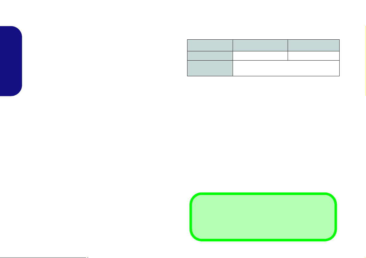
Model Differences
This notebook series includes two different model types
that mainly differ as indicated in the table below.
Feature Model A Model B
3D
Video Adapters
Supported
Not Supported Supported
See "Specifications" on page 34 for a full list
of video adapters supported by each model.
Table 1 - Model Differences
System Software
Your computer may already come with system software
pre-installed. Where this is not the case, or where you are
re-configuring your computer for a different system, you
will find this manual refers to Microsoft Windows 7.
HDD RAID Support
Your hard disk(s) can be set up in AHCI mode or RAID
mode (for increased performance or protection). Note that
setting up your hard disk(s) in RAID mode needs to be
done prior to installing the Windows OS (see "RAID Set-
up" on page 5).
4
Page 11

RAID Setup
You may use your hard disks in combination with Striping
(RAID 0), Mirroring (RAID 1), Parity Across Disks
(RAID 5) for either fault tolerance or performance.
RAID Level Description
Identical drives reading and writing data in par-
RAID 0
(at lease two
hard disks
needed)
RAID 1
(at lease two
hard disks
needed)
RAID 5
(three hard
disks
needed)
allel to increase performance. RAID 0 implements a striped disk array and the data is
broken into blocks and each block is written to
a separate disk drive.
RAID 0 (a striped array) is not fault-tolerant.
The failure of one drive will result in the loss of
all data in the array.
Identical drives in a mirrored configuration used
to protect data. Should a drive that is part of a
mirrored array fail, the mirrored drive (which
contains identical data) will handle all the data.
When a new replacement drive is installed,
data to the new drive is rebuilt from the mirrored drive to restore fault tolerance.
RAID 1 (mirrored array) provides full data protection, as data can simply be copied from a
healthy disk to a replacement for any failed
disk.
Identical drives (at least three drives must be
used) in a parity across disks configuration are
used to protect data and increase perfor-
mance. A RAID 5 array can withstand a single
disk failure without losing access to data.
Prepare the following before setting up your serial ATA
hard disks in RAID mode:
•The Microsoft Windows 7 OS disc.
•A second hard disk installed in the Primary HDD bay for
RAID level 0 or 1
.
OR
A second hard disk installed in the Primary HDD bay, and
a third hard disk in the Secondary HDD bay for RAID
level 5.
•The Device Drivers & Utilities + User’s Manual disc.
• A USB Flash drive or external USB hard disk drive with
the RAID folder from the Device Drivers & Utilities +
User’s Manual disc copied on to it.
RAID Setup Procedure
Part I: BIOS
1. Start-up your computer and press F2 to enter the BIOS.
2. Go to the Advanced menu, select SATA Mode and press
Enter.
3. Select RAID Mode.
4. Press Esc and go to the Boot menu.
5. Set the CD/DVD-ROM Drive (make sure the Microsoft
Windows OS disc is inserted) as the first device in the boot
order from the Boot menu.
6. Select Save Changes and Reset from the Exit menu (or press
F4) and press Enter to exit the BIOS and reboot the computer.
English
Table 2 - RAID Description
5
Page 12

Part II: Intel Matrix
Figure 2
RAID
Created
1. Press Ctrl + i to enter RAID configuration menu.
2. Select 1.Create RAID Volume and press Enter.
3. Type the RAID volume name and then press Tab or Enter to
advance to the next field.
4. Specify (use the up and down arrow keys) the RAID level
(RAID 0 or RAID 1 or RAID 5 - see Table 2 on page 5) and
then press Tab or Enter to advance to the next field.
5. Press Enter and the system will select the physical disks to use.
English
6. Press Enter and select (if applicable) the Strip Size (best set to
default).
7. Press Enter and select the Capacity size (best set to default).
8. Press Enter to select Create Volume.
9. Press Enter to create the volume, and confirm the selection by
pressing Y.
10. This will now return to the main menu.
11. Select 4.Exit and press Enter, then press Y to exit the RAID
configuration menu.
12. Make sure the Windows 7 OS DVD is in the DVD drive and as
the computer starts up it will automatically boot from the
Windows 7 OS DVD (you will be prompted to press a key to
boot from the DVD).
13. Press Enter to continue installing the operating system as
normal (see your Windows documentation if you need help on
installing the Windows OS).
A driver is included on the Device Drivers & Utilities +
User’s Manual disc that will need to be installed as part of
the Windows installation procedure. However you will
need to go to an operable computer and copy the driver to
a USB Flash drive or external USB hard disk.
1. Go to the operable computer and copy the 00IRST folder from
the location below (D: denotes your DVD drive) on the Device
Drivers & Utilities + User’s Manual disc to the USB Flash drive
or external USB hard disk.
• Windows 7 32bit
D:\Option\00IRST\f6flpy\RSTe_f6_iaStorA_32\
• Windows 7 64bit
D:\Option\00IRST\f6flpy\RSTe_f6_iaStorA_64\
2. Install Windows from your Microsoft Windows 7 disc and click
to select Load Driver when the “Where do you want to install
Windows?” screen appears.
3. Click Browse and browse to the location you copied the files to
on your USB Flash drive or external USB hard disk (X: denotes
your USB Flash drive or external USB hard disk):
• Windows 7 32bit
X:\00IRST\f6flpy\RSTe_f6_iaStorA_32\
• Windows 7 64bit
X:\00IRST\f6flpy\RSTe_f6_iaStorA_64\
4. Follow the on-screen instructions to install the Windows 7
operating system.
6
Page 13

System Map: Front View with LCD Panel Open
Figure 3
Front View with LCD
Panel Open
1. PC Camera (Optional)
2. Built-In Microphone
3. PC Camera LED
4. LCD
5. LED Status Indicators
6. Touch Sensor Instant
Keys
7. Speakers
8. 3D IR Emitter (Model B
Only)
9. Power Button
10. Keyboard
11. Touchpad & Buttons
12. Fingerprint Reader
13. LCD Panel Color LED
13
2
1
6
8
9
5
3
Wireless Device
Operation Aboard
Aircraft
The use of any portable
electronic transmission
devices (e.g. WLAN or
Bluetooth) aboard aircraft is usually prohibited. Make sure any
wireless modules are
OFF if you are using the
computer aboard aircraft.
Use the appropriate
function key combination/touch sensor instant
key to toggle power to
any wireless modules,
and check the indicators
to see if any modules
are powered on or not
(see Table 4 on
page 8).
10
4
2
7
7
7
11
7
12
7
English
7
Page 14
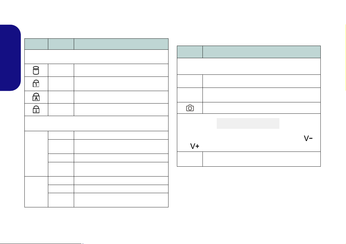
LED Indicators
The LED indicators on the computer display helpful information about the current status of the computer.
Icon
Color Description
Touch Sensor Instant Keys
Press the touch sensor instant keys on the computer to toggle the appropriate function on/off. When a module is
powered on the appropriate icon will be highlighted blue.
Icon Description
English
8
Green Hard Disk Activity
Green
Green Caps Lock Activated
Green Scroll Lock Activated
Orange The AC/DC Adapter is Plugged In
Blinking
Orange
Green The Computer is On
Blinking
Green
Orange The Battery is Charging
Green The Battery is Fully Charged
Blinking
Orange
Number Lock (Numeric Keypad) Acti-
vated
The powered USB 3.0 Port is on
(see page 14)
The Computer is in Sleep Mode
The Battery Has Reached Critically Low
Power Status
Table 3 - LED Indicators
Bluetooth Module Power Toggle
Wireless LAN Module Power Toggle
PC Camera Module Power Toggle
Volume Control (Press and hold your finger at either end /
of the volume control to adjust the system volume)
Mute Toggle
Table 4 - Touch Sensor Instant Keys
Page 15
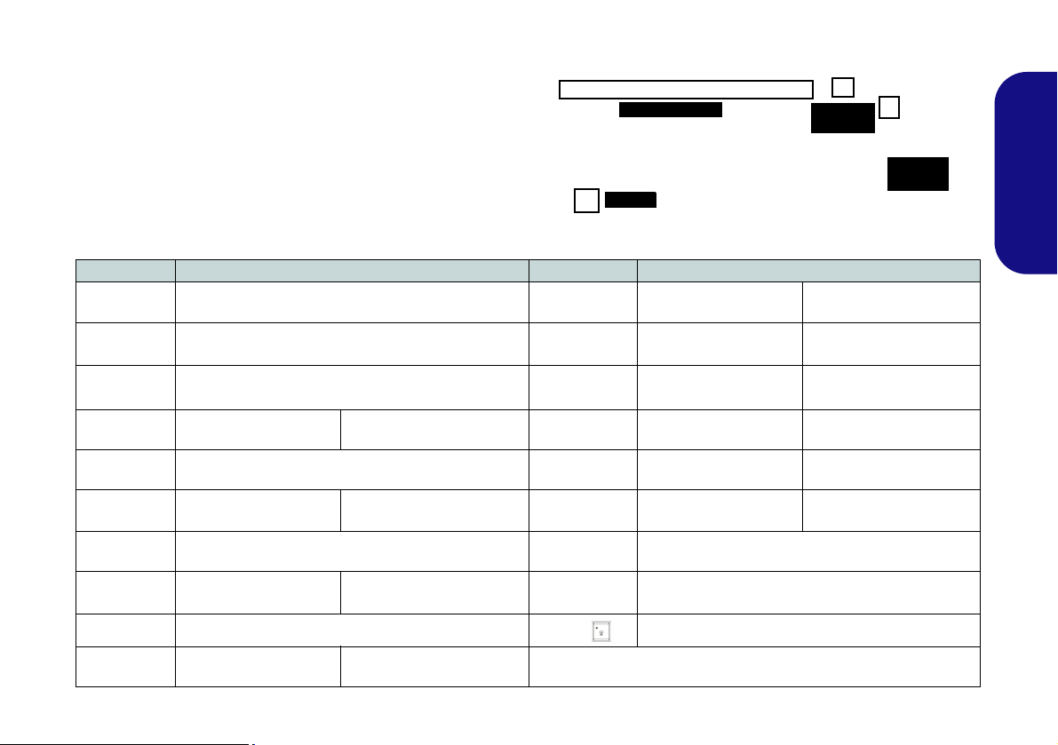
Keyboard & Function Keys
Function Keys
Numeric
Keypad
Fn Key
ScrLk &
NumLk
Figure 4 - Keyboard
The keyboard includes a numeric keypad (on the right side
of the keyboard) for easy numeric data input. Pressing Fn
+ NumLk turns on/off the numeric keypad. It also features
function keys to allow you to change operational features
instantly. The function keys (F1 - F12 etc.) will act as hot
keys when pressed while the Fn key is held down. In addition to the basic function key combinations, visual indicators are available when the hot key driver is installed.
Keys Function/Visual Indicators Keys Function/Visual Indicators
Fn + ~ Play/Pause (in Audio/Video Programs)
Fn + 1 Fan Automatic Control/ Full Power
Fn + 5
Fn + F1 Touchpad Toggle Fn + NumLk Number Lock Toggle
Audio Toggle - Toggle between Standard and
Enhanced Audio (see page 20)
Fn + F10/
Fn + F11/
Fn + F12/
PC Camera Power
Toggle
WLAN Module Power
Toggle
Bluetooth Module
Power Toggle
English
Fn + F2
Fn + F3/
Fn + F4 Sleep Toggle
Fn + F5/F6
Fn + F7 Display Toggle
Fn + F8/F9
(Press a key to or use Touchpad to turn on)
Mute Toggle Caps Lock Caps Lock Toggle
Volume Decrease/
Brightness Decrease/
Turn LCD Backlight Off
Increase
Increase
Fn + ScrLk Scroll Lock Toggle
Fn + Power
Button
Fn + Esc Control Center Toggle (see page 11)
Fn +
Powered USB Port Power Toggle (see page 14)
Keyboard LED Toggle (see page 10)
Table 5 - Function Keys & Visual Indicators
9
Page 16
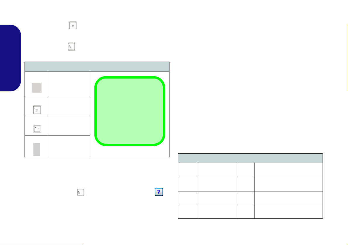
Keyboard LED
*Illumination Keys
Note that the keyboard illumination (increase/decrease) keys may be
used to configure the keyboard LED in Custom
Mode only.
Help Button
Keyboard Sections
Effects Buttons
Color Swatches
Press Fn plus the key to toggle the keyboard LED on/
off. The keyboard LED may be configured using the Fn +
key combination outlined in the table below. In addition
press Fn plus the key to launch the keyboard backlight
application to configure the settings.
• Click a section of the keyboard and the color buttons will
be displayed.
• Click a color swatch to apply the color to the selected section when not overidden by any effect applied.
• Click on any of the effect buttons to apply random colors,
wave or flashing effects etc.
English
Keyboard Backlight Application
The Keyboard Backlight application can be accessed by
pressing the Fn plus key. Click the Help button in
the application to display the configuration keys.
• Click the Custom button to display the three sections
10
Keyboard LED Function key Combinations
Fn +
Fn +
Fn +
Fn +
Launch the
Keyboard
Backlight
Application
Toggle the
Keyboard LED
On/Off
*Keyboard LED
Illumination
Decrease
*Keyboard LED
Illumination
Increase
Table 6 - Keyboard LEDs
of the keyboard which may be configured.
Figure 5 - Keyboard Backlight Application
Effects Buttons & Help
LED Effects Buttons
Random Color Up/Down Wave
Dancing Effect Breathing (All Colors)
Tempo Beat
Flashing
Table 7 - LED Effects Buttons
Cycle (Colors as Selected in
RGB)
Custom - Display & Configure
Keyboard Sections & Colors
Page 17

Control Center
Press the Fn + Esc key combination, or double-click the icon in the notification area of the taskbar to toggle the
Control Center on/off. The Control Center gives quick access to frequently used controls, and enables you to quickly
turn modules on/off.
Figure 6 - Control Center
Click on any button to turn any of the modules (e.g. Touchpad, Camera) on/off. Click on Power Conservation to switch
between Performance, Balanced or Energy Star modes. Click on the buttons (or just click and hold the mouse button)
to adjust the slider for Brightness/Volume. Click on Display Switch/Time Zone/ Desktop Background to bring up
the appropriate Windows control panel. Click on the Sleep button to put the computer into Hibernate or Sleep modes.
English
11
Page 18
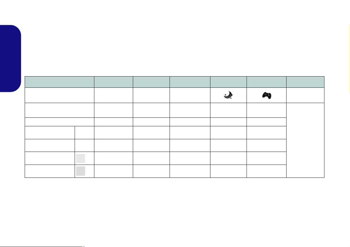
Power Modes
You can set a Power Mode by clicking the appropriate icon at the top of the Control Center. Each power mode will
affect the power status of modules (e.g. WLAN or Camera), screen brightness, Touchpad power and Silent Mode. You
can click a Control Center icon to set an overall power mode and then click individual icons in the Control Center to
power on/off any modules etc.
Table 8 illustrates the basic settings for each power mode. If you choose User Defined the settings will correspond to
your selected system settings.
English
Modes Power Saving Flight Entertainment Quiet Performance User Defined
Icon
Power Plan Power Saver Balanced Power Saver Power Saver
Power Conservation Mode Energy Star BIOS Default Energy Star Energy Star Performance
Brightness 14 42 100 42 100
WLAN OFF OFF ON ON ON
PC Camera OFF OFF OFF ON ON
Touchpad ON ON ON ON ON
Table 8 - Power Modes
High Perfor-
mance
12
User Defined
Page 19

Power Status
The Power Status icon will show
whether you are currently powered by
the battery, or by the AC/DC adapter
plugged in to a working power outlet.
The power status bar will show the
current battery charge state.
Brightness
The Brightness icon will show the
current screen brightness level. You
can use the slider to adjust the screen
brightness or the Fn + F8/F9 key combinations, or use the Fn + F2 key combination to turn off the LED backlight
(press any key to turn it on again).
Note that screen brightness is also effected by the Power Mode selected.
Volume
The Volume icon will show the current volume level. You can use the
slider to adjust the Volume or the Fn +
F5/F6 key combinations, or use the
Fn + F3 key combination to mute the
volume.
Power Conservation
This system supports Energy Star
power management features that place
computers (CPU, hard drive, etc.) into
a low-power sleep mode after a designated period of inactivity. Click either
the Performance, Balanced or Ener-
gy Star button.
Sleep
Click the Sleep button to bring up the
Hibernate or Sleep buttons,
and click either button to have the
computer enter the appropriate powersaving mode.
Display Switch
Click the Display Switch button to access the menu (or use the + P key
combination) and select the appropriate display mode.
Time Zone
Clicking the Time Zone button will
access the Date and Time Windows
control panel.
Desktop Background
Clicking the Desktop Background
button will allow you to change the
desktop background picture.
K/B LED
Click to access the keyboard setting
control to configure the keyboard
LED.
TouchPad/PC Camera/Wireless
LAN Module /Bluetooth Module
Click any of these buttons to toggle
the Touchpad or module’s power status. A crossed out icon will appear
over the top left of the icon when
it is off
. Note that the power status of a
module, and Touchpad power, is also
effected by the Power Mode selected.
English
13
Page 20

System Map: Front, Left & Right Views
Figure 7
Front, Left & Right Views
1. LED Power Indicators
2. Express Card Slot (54/34)
3. Multi-In-1 Card Reader
4. DVI-Out Port
5. RJ-45 LAN Jack
6. HDMI-Out Port
7. DisplayPort
8. USB 3.0 Ports
9. Combined eSATA/Powered
USB 3.0 Port (See Below)
10. Mini-IEEE 1394b Port
11. Optical Device Drive Bay
12. Headphone-In Jack
13. Microphone-In Jack
14. Line-In Jack
15. S/PDIF-Out Jack
16. USB 2.0 Ports
17. Sub Woofer
18. Security Lock Slot
3
6
4
5
7
2
1
Front
Left
Right
12
17
16
15
14
10
18
11
USB
The USB 3.0 ports
are colored blue. USB 3.0 will transfer data much faster than USB 2.0,
and is backwards-compatible with USB 2.0. When the powered USB 3.0 port
is on it will
supply power (for charging devices only, not for operating devices) when the system is off
but still powered by the AC/DC adapter plugged into a working outlet, or powered by the battery
with a capacity level above 20% (this may not work with certain devices - see page 33). Toggle
power to this port by using Fn + power button.
HDMI
Note that the HDMI Port supports video and audio signals to attached external displays (Note
THX Tru Studio Pro will be disabled when you are connecting to an external display through an
HDMI connection - see page 22).
8
9
9
8
13
8
16
English
14
Page 21
System Map: Rear & Bottom Views
Figure 8
Rear & Bottom Views
1. DC-In Jack
2. Vent
3. Component Bay Cover
4. Battery
5. Hard Disk Bay Cover
CPU
The CPU is not a user
serviceable part. Accessing the CPU in any
way may violate your
warranty.
Overheating
To prevent your computer from overheating
make sure nothing
blocks any vent while
the computer is in use.
2
2
1
3
5
2
2
Battery Information
Always completely discharge, then fully charge, a new battery before using it. Completely discharge and charge the battery at least once every 30 days or after about 20 partial discharges
(see the expanded User’s Manual on the Device Drivers & Utilities + User’s Manual disc).
4
2
2
English
15
Page 22

Video Features
You can switch display devices, and configure display options, from the Display control panel in Windows and/or
the NVIDIA Control Panel as long as the video driver is
installed.
Display Devices
Besides the built-in LCD, you can also use an external
VGA monitor (CRT)/external Flat Panel Display or TV
(connected to the DVI-Out port/HDMI-Out port/DisplayPort) as your display device.
To access Display control panel in Windows:
1. Click Start, and click Control Panel (or point to Settings and
English
click Control Panel).
2. Click Display (icon) - in the Appearances and
Personalization category.
3. Click Adjust Screen Resolution/Adjust resolution.
OR
4. Alternatively you can right-click the desktop and select Screen
resolution.
5. Use the dropbox to select the screen resolution.
6. Click Advanced settings.
To access the NVIDIA Control Panel:
1. Click Start, and click Control Panel (or point to Settings and
click Control Panel).
2. Click NVIDIA Control Panel (icon) - in the Appearances and
Personalization category.
OR
3. Right-click the desktop and select NVIDIA Control Panel from
the menu.
SLI Multi GPU Configuration
This computer features an NVIDIA Scalable Link Interface (SLI) that improves graphic quality and performance
by combining dual NVIDIA GPUs (two video cards are
required) in a single system. To enable/disable SLI Configuration:
1. Go to the NVIDIA Control Panel
2. Click “+” next to 3D Settings if its sub-items are not shown and
then click Set SLI Configuration.
Figure 9 - Set SLI Configuration
3. Click “Enable SLI technology (recommended)”.
4. Click to “Select the display to view the SLI rendered content
on.” (only a single display may be used).
5. Click Apply and Yes to restart the computer.
.
16
Page 23

NVIDIA 3D VISION Shutter Glasses Kit
Important Safety Instructions
Make sure you read all the enclosed safety instructions and
precautions included in the NVIDIA 3D Vision Kit before
setting up the 3D Glasses and IR Emitter. Follow the setup
instructions provided in the documentation to set up the 3D
Vision kit safely and take the “User Vision Test,” which will
initiate when you turn on your GeForce 3D Vision for the
first time. If you cannot see the image in 3D during the test,
you should DISCONTINUE USE IMMEDIATELY. Continued use may result in health-related complications.
3D Icon
USB Connection & 3D Glasses
The light on the glasses will flash amber while charging, and solid amber when fully charged.
The glasses hold approximately 40 hours of viewing per
full charge. Flashing red indicates that less than 2 hours
of charge are remaining.
The indicator light displays for about 30 seconds after
turning the glasses on.
The NVIDIA 3DVISION shutter glasses kit is supported
only by models which include the built-in 3D emitter and
shutter glasses kit.
The NVIDIA 3DVISION shutter glasses kit is supplied
with a single pair of shutter glasses and all necessary cables etc. Set up the hardware (run the set up wizard as indicated on page 18) as instructed in the manual supplied
with the kit, however make sure you have installed the
NVIDIA driver (see "USB 3.0" on page 24) from the
Device Drivers & Utilities + User’s Manual disc. For fur-
ther details contact your service center.
Stereoscopic 3D Hardware Setup
If your computer model features a built-in 3D IR emitter
the loaction is illustrated below. The effective viewing angles of the emitter are illustrated in Figure 11 on page 18.
Make sure that you are viewing the notebook screen within the area highlighted in order to get the proper stereoscopic 3D effect.
Figure 10 - IR Emitter Location
17
English
Page 24

Viewing Angles
75
Figure 12
Set Up
Stereo-
scopic 3D
Enable sterescopic 3D
The emitter’s horizontal viewing angle is 100 degrees.
The emitter’s vertical viewing angle is 75 degrees.
English
Figure 11 - Emitter - Viewing Angles
2. Double-click NVIDIA Control Panel (click "Classic View" from
the left of the menu if you are in Control Panel Home).
3. Double-click Stereoscopic 3D (if the sub-menus are not
visible), and then click Set up stereoscopic 3D.
4. Click Enable stereoscopic 3D (tickbox) to enable 3D Vision.
5. Click Apply to save the setting.
6. Select the drop-down menu at the bottom of the screen to Test
sterescopic 3D.
7. Select Run Setup Wizard from the drop-down menu (you can
also select Run Medical Image Tes t from this menu).
8. Follow the on-screen instructions to set up 3D Vision and click
“Next” to progress through the steps (this notebook has a builtin emitter).
Set Up Stereoscopic 3D
After the NVIDIA driver has been installed you can setup
NVIDIA 3D Vision.
1. Click Start, and click Control Panel (or point to Settings and
click Control Panel).
18
9. During the setup procedure you will need to click to answer
questions on what you see in 3D on the screen.
10. Configure the stereoscopic 3D from the control panels (make
sure you charge the 3D shutter glasses by plugging them into
one of the computer’s USB ports using the USB cable
provided).
11. The stereoscopic depth may be adjusted by using the control
panel slider.
Page 25

Power Options
Figure 13 - Power Options
Figure 14
Dual Power
Adapters &
Converter Box
The Power Options (Hardware and Sound menu) control panel icon in Windows allows you to configure power
management features for your computer. You can conserve power by means of power plans and configure the
options for the power button, sleep button (Fn + F4),
computer lid (when closed), display and sleep mode (the
default power saving state) from the left menu. Note that
the Power saver plan may have an affect on computer
performance.
Click to select one of the existing plans, or click Create a
power plan in the left menu and select the options to create a new plan. Click Change Plan Settings and click
Change advanced power settings to access further configuration options.
SLI Multi GPU Configuration & Power
Note that due to the high power and system demands created by enabling SLI Configuration, you should not power
the system using the battery only and you will require
identical dual power adapters, connected to a power converter box, to power the system.
English
• Only enable SLI configuration if the system is powered
by identical dual power adapters connected by means
of the power converter box (factory option).
• If the computer is currently powered by battery only do not
enable SLI configuration.
• If you have currently enabled SLI configuration, and the
computer is powered by the AC/DC adapter, do not switch
to battery power only (or go to the NVIDIA Control
Panel and disable SLI configuration before switching to
battery power only).
19
Page 26

Audio Features
Figure 15
Sound
Playback
Options
You can configure the audio options on your computer
from the Sound control panel in Windows, or from the
Realtek HD Audio Manager
tion area/control panel (right-click the notification area
icon to bring up an audio menu). The volume may also
be adjusted by means of the Fn + F5/F6 key combination.
English
Audio Notes (Fn + 5)
This computer features the Fn + 5 key combination to toggle between standard audio and enhanced audio. Note the
following which applies to software mode audio configuration through the computer’s internal speakers only (this
does not apply to surround sound when configured
through external Quadrophonic, 5.1 or 7.1 speaker systems):
• When the Speaker Configuration in Realtek HD Audio
Manager is set to Stereo, you can use the Fn + 5 key combination to help increase the volume through the speakers.
/ icon in the notifica-
Audio Setup for HDMI
HDMI supports video and audio signals. In some cases it
will be necessary to go to the Sound control panel and
manually configure the HDMI audio output.
1. Click Start, and click Control Panel (or point to Settings and
click Control Panel).
2. Click Sound (Hardware and Sound).
3. Click Playback (tab).
4. The playback device will be selected.
5. In some cases you may need to select the audio device and
click Set Default (button).
6. Double-click the device to access the control panel tabs.
7. Adjust the HDMI settings from the control panel tabs.
8. Click OK to close the Sound control panel.
• When the Speaker Configuration in Realtek HD Audio
Manager is set to Quadrophonic, 5.1/7.1 Speaker, the
best audio configuration will be obtained with the combination of the Speaker Configuration set to Quadro-
phonic, 5.1/7.1 Speaker, and the THX TruStudio AP
turned ON.
Note that the Fn + 5 key combination is a toggle so you
will need to press the key combination to test if the affect
is applied or not.
20
Page 27

Setup for Audio Recording
Figure 16
Realtek HD
Audio Man-
ager - Re-
cording
Setup
Figure 17
Speaker Con-
figuration
To record audio sources on your computer at optimum
quality follow the instructions below:
3. Click Speakers (tab) and click Speaker Configuration (tab).
4. Select 5.1 Speaker or 7.1 Speaker from the Speaker
Configuration pull-down menu.
1. Click Start, and click Control Panel (or point to Settings and
click Control Panel).
2. Click Realtek HD Audio Manager (or right-click the notification
area icon
3. Click Microphone Effects (tab) in Microphone (tab), and then
click to select Noise Suppression (button), or adjust the
Recording Volume level to around 60, to obtain the optimum
recording quality.
4. Click OK to close the Sound control panel.
and select Sound Manager).
Setup for 5.1 or 7.1 Surround Sound
To setup your system for 5.1 or 7.1 surround sound you
will need to connect the audio cables to the Line-In, Headphone-Out, Microphone-In and S/PDIF-Out jacks (7.1
Speaker only).
1. Click Start, and click Control Panel (or point to Settings and
click Control Panel) and make sure you are in Classic View.
2. Click Realtek HD Audio Manager (or right-click the notification
area icon
and select Sound Manager).
English
5. Plug the front speaker cables into the Headphone-Out Jack.
6. Plug in the cables (you may require an adapter to connect each
cable to the appropriate jack e.g a stereo mini to dual RCA
adapter) from your speakers as follows:
• Line-In Jack = Side Speaker Out
• Microphone-In Jack = Center/Subwoofer Speaker Out
• S/PDIF-Out Jack = Rear Speaker Out (7.1 Speaker only)
7. As you plug in each cable a dialog box will pop up.
8. Click to put a tick in the appropriate box according to the
speaker plugged-in (e.g. Rear Speaker Out), and the n click OK
to save the setting.
9. Click OK to exit Realtek HD Audio Manager.
Figure 18 - Connected Device Auto Popup
21
Page 28

Sound Blaster Audio
Figure 19
Creative
(Start)
Menu
Items
Figure 20
THX TruStudio
Pro HDMI Dis-
play Warning
THX Audio & HDMI
Note that the THX audio effects do not apply to
audio generated through an HDMI connection.
Install the Sound Blaster AP to allow you to configure
the audio settings to your requirements for the best performance in games, music and movies.
The Sound Blaster audio controls include the Sound
Blaster Console, desktop gadgets, Creative ALchemy,
Creative Music Server and the THX TruStudio Pro application.
English
Sound Blaster X-Fi MB-2 Audio AP Instal-
lation
1. Click Option Drivers (button).
2. Click 6.Install SBX-Fi MB2 AP > Yes.
3. Choose the language you prefer and click Yes.
4. Click Next > Full Installation (button).
5. Click Next > Finish to restart the computer.
Sound Blaster AP Activation
On the first run of Sound Blaster AP you will need to activate the application.
1. To activate the application you will need to be connected to the
internet.
2. Double-click the Sound Blaster icon on the desktop
and click the Activate button.
3. The program will connect to the internet to verify the activation
key.
4. Click Finish to complete the application activation.
5. Restart the computer.
22
Sound Blaster Application
The application can
be run from the
shortcut in the
Start menu (Start
> All Programs >
Creative > Sound
Blaster X-Fi MB-
2).
THX Tru Studio Pro & HDMI
1. When you connect an HDMI display to the HDMI-Out port, the
THX TruStudio Pro controls will be disabled.
2. A warning box will pop-up and will prompt “Do you want to
select another audio device now?”.
3. Click No to continue using the HDMI audio output from your
external display (do not attempt to select another audio device
when connected to the external HDMI display).
Page 29
Driver Installation
Driver Installation & Power
When installing drivers make sure your computer is
powered by the AC/DC adapter connected to a working
power source. Some drivers draw a significant amount
of power during the installation procedure, and if the remaining battery capacity is not adequate this may cause
the system to shut down and cause system problems
(note that there is no safety issue involved here, and the
battery will be rechargeable within 1 minute).
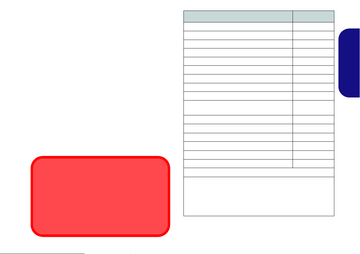
The Device Drivers & Utilities + User’s Manual disc con-
tains the drivers and utilities necessary for the proper operation of the computer. Insert the disc and click Install
Drivers (button), or Option Drivers (button) to access
the Optional driver menu. Install the drivers in the order
indicated in Table 9. Click to select the drivers you wish
to install (you should note down the drivers as you install
them). Note: If you need to reinstall any driver, you
should uninstall the driver first.
Manual Driver Installation
Click the Browse CD/DVD button in the Drivers Installer application and browse to the executable file in the ap-
propriate driver folder.
If a
Found New Hardware
stallation procedure, click Cancel and follow the installation procedure as directed.
wizard appears
during the in-
Driver (Windows 7 with SP1)* Page#
Chipset page 24
Video page 24
LAN page 25
CardReader page 24
Touchpad page 24
Hot Key page 24
USB 3.0 page 24
Intel MEI page 24
Audio page 24
Intel Rapid Storage Technology
(required for hard disks in AHCI mode)
PC Camera page 25
Wireless LAN Module (Optional)
Fingerprint Reader page 28
Bluetooth Module (Optional)
TPM page 31
Sound Blaster Audio page 22
Enable Windows Update
*Note all drivers provided are for Windows 7 with Service Pack 1.
**No driver installation required for 3rd party Bluetooth 2.1 mod-
ules.
***After installing all the drivers make sure you enable Windows
Update in order to get all the latest security updates etc. (all updates
will include the latest hotfixes from Microsoft).
Table 9 - Driver Installation
**
***
page 24
page 27
page 29
23
English
Page 30

Chipset
1. Click Install Drivers (button).
2. Click 1.Install Chipset Driver > Yes.
3. Click Next > Yes > Next > Next.
4. Click Finish to restart the computer.
USB 3.0
1. Click 2.Install USB 3.0 Driver > Yes.
English
2. Choose the language you prefer and click OK.
3. Click Next.
4. Click the button to accept the license and then click
Next.
5. Click Finish.
Video
1. Click 3.Install VGA Driver > Yes.
2. Click AGREE AND CONTINUE (button) to accept the
terms of the license agreement.
3. Click Next.
4. Click RESTART NOW to restart the computer.
LAN
1. Click 4.Install LAN Driver > Yes.
2. Click Install Drivers and Software (button).
3. Click Next.
4. Click the button to accept the license agreement and
click Next.
5. Click Next > Install > Finish.
CardReader
1. Click 4.Install Cardreader Driver > Yes.
2. Click Install > Finish.
Touchpad
1. Click 6.Install Touchpad Driver > Yes.
2. Click Next.
3. Click the button to accept the license and click Next.
4. Click Finish > Restart Now to restart the computer.
Hot Key
1. Click 7.Install Hotkey AP > Yes.
2. Click Next > Next.
3. Click Fini sh > Fin ish to restart the computer.
Intel MEI
1. Click 8.Install MEI Driver > Yes.
2. Click Next > Yes > Next > Next.
3. Click Finish.
Audio
1. Click 9.Install Audio Driver > Yes.
2. Click Next > Finish to restart the computer.
Intel Rapid Storage Technology
1. Click Option Drivers (button).
2. Click 7.Install IRST Driver > Yes.
3. Click Next > Yes > Next.
4. Click Finish to restart the computer (you will need to
restart the system again after the computer has rebooted).
24
Page 31

PC Camera
Before installing the PC Camera driver, make sure the PC
Camera module is powered on. Use the Fn + F10 key
combination
er to the PC Camera module. When the PC Camera module is powered on, the LED will be highighted and the
on-screen visual indicator will briefly be displayed.
PC Camera Driver Installation
1. Click Option Drivers (button).
2. Click 1.Install WebCam Driver > Yes.
3. Click Finish to restart the computer.
OR
Click Next > Finish.
4. Run the camera application from the desktop shortcut
(if the hardware is turned off use the Fn + F10 key
combination or touch sensor instant key to turn it on
again).
or touch sensor instant key to toggle pow-
PC Camera Audio Setup
If you wish to capture video & audio with your camera, it
is necessary to setup the audio recording options in Win-
dows.
English
1. Click Start, and click Control Panel (or point to Settings and
click Control Panel).
2. Click Sound (Hardware and Sound).
3. Click Recording (tab).
4. Right-click Microphone (Realtek High Definition Audio) and
make sure the item is not disabled.
5. Double-click Microphone (or select Properties from the rightclick menu).
6. Click Levels (tab), and adjust the Microphone and
Microphone Boost sliders to the level required.
7. Click OK and close the control panels.
8. Run the camera application from the desktop shortcut.
9. Go to the Devices menu heading and select Microphone
(Realtek....) (it should have a tick alongside it).
10. Go to the Capture menu heading and select Capture Audio (it
should have a tick alongside it).
11. To obtain the best sound recording quality enable Noise
Supression in the Realtek HD Audio Manager control panel
(see "Setup for Audio Recording" on page 21).
25
Page 32

Camera Application
The camera application is a video viewer useful for general purpose video viewing and testing, and can capture video files to .avi format.
1. Run the camera application from the desktop shortcut (it is recommended that you Set Capture File before the capture process - see “Set Capture File” below).
2. Go to the Capture menu heading (if you wish to capture audio
English
check "PC Camera Audio Setup" on page 25) and select
Start Capture.
3. Click OK (the file location will be di splayed in the pop-up b ox) to
start capturing the video, and press Esc to stop the capture
(you can view the file using the Windows Media Player).
Set Capture File
Prior to capturing video files you may select the Set Capture File... option in the File menu, and set the file name
and location before capture (this will help avoid accidentally overwriting files). Set the name and location then
click Open, then set the “Capture file size:” and click OK.
You can then start the capture process as above.
Reducing Video File Size
Note that capturing high resolution video files requires a
substantial amount of disk space for each file. After recording video, check the video file size (right-click the file
and select Properties) and the remaining free space on
your hard disk (go to Computer, right-click the hard disk,
and select Properties). If necessary you can remove the
recorded video file to a removable medium e.g. CD, DVD
or USB Flash drive.
Note that the Windows system requires a minimum of
15GB of free space on the C: drive system partition. In
order to prevent system problems it is recommended that
you save the captured video file to a location other than
the C: drive, limit the file size of the captured video or reduce video resolution.
To Reduce Video Resolution Output Size:
1. Run the camera application from the desktop shortcut.
2. Go to Options and scroll down to select Video Capture Pin....
3. Click the Output Size drop box and select a lower resolution
size in order to reduce the captured file size.
26
Page 33

Wireless LAN Module (Option)
Before installing the Wireless LAN driver, use the Fn +
F11 key combination or touch sensor instant key to
power ON the WLAN module. When the Wireless LAN
module is powered on, the LED will be highlighted and
the on-screen visual indicator will briefly be displayed.
WLAN Driver Installation
Follow the instructions below:
WLAN/WLAN and Bluetooth Combo (Intel)
1. Click Option Drivers (button).
2. Click 2.Install WLAN Driver > Yes.
3. Click Next > Next.
4. Click the button to accept the license and click Next.
5. Click Typical (buttom) or Custom (buttom).
6. Click Install > Finish.
WLAN and Bluetooth 4.0 Combo (Third Party)
1. Click Option Drivers (button).
2. Click 2.Install WLAN Driver > Yes.
3. Click Next.
4. Click Finish to restart the computer.
Connecting to a Wireless Network
The operating system is the default setting for Wireless
LAN control in Windows. Make sure the Wireless LAN
module is turned on.
1. Click the taskbar wireless icon , and then double-click an
access point to connect to or click to Open Network and Shar-
ing Center if you do not see a network you want to connect to
in the taskbar menu (a list of options will appear allowing setting
changes, and creating a new network)
2. You may need to enter a security key for any access point to
which you are trying to connect.
3. Click to selct a network location (e.g. Home, Work or Public).
4. Click “View or change settings in Network and Sharing
Center” to access further options for the connection.
5. Click the taskbar icon to see any currently connected
networks.
6. To disconnect from the wireless network you can click the
taskbar wireless icon , click the active connection and then
click Disconnect (button).
.
English
27
Page 34

Fingerprint Reader
Help
Click the Help icon and select a
help topic from the drop-down menu.
Get more help will provide a more comprehensive list of help topics.
Figure 21
AuthenTec
TrueSuite -
Settings
Install the driver and enroll your fingerprints as instructed
below before use.
Fingerprint Reader Driver Installation
1. Click Option Drivers (button).
2. Click 3.Install Fingerprint Driver > Yes.
English
3. Click Next.
4. Click the button to accept the license and click Next.
5. Click Next > Install.
6. Click Finish > Yes to restart the computer.
User Enrollment
1. Click Start > Programs/All Programs > AuthenTec TrueSuite.
2. Click Yes when you have identified your fingerprint sensor.
3. Click Yes when you are ready to enroll your fingerprints.
4. Click on the fingerprint diagram to select any finger to enroll.
5. You will be required to enter your Windows password (you will
be prompted to create a password if you have not already done
so) at this point (click OK to confirm the password entry).
6. Swipe the finger until the progress bar reaches 100% to enroll
that finger.
7. You will be prompted to select ano ther finger for enrol lment (it is
recommended that you enroll a number of fingers).
8. Click the button to continue once you have enrolled a number of
9. Enter the required information and click the button to register
fingerprints.
your software, or click to register later.
28
10. Your fingerprints will now be enrolled (you may enroll any
additional fingerprints at any time).
Settings
Click the Settings button on the menu bar to access the
personalization settings for AuthenTec TrueSuite. Here
you can choose to enable/disable Website Log On, QuickLaunch, Fast User Switching and the desktop icon. You
can also select the Theme and export/import identities.
Click the Save button to save any changes made.
Page 35

Bluetooth Module (Option)
Before installing the Bluetooth driver, use the Fn + F12
key combination or touch sensor instant key to power
ON the Bluetooth module. When the Bluetooth module is
powered on, the LED will be highlighted and the onscreen visual indicator will briefly be displayed.
Use the Fn + F11 and Fn + F12 key combinations
gle power to the Combo Bluetooth and WLAN module.
to tog-
Bluetooth Driver Installation
Follow the instructions below:
WLAN and Bluetooth Combo (Intel)
1. Click Option Drivers (button).
2. Click 4.Install Combo BT Driver > Yes.
3. Click Next > Next.
4. Click the button to accept the license and click Next.
5. Click Next > Finish.
WLAN and Bluetooth 4.0 Combo (Third Party)
1. Click Option Drivers (button).
2. Click 4.Install Combo BT Driver > Yes.
3. Click Next.
4. Click Finish to restart the computer.
English
29
Page 36

Bluetooth Configuration
High Speed Bluetooth Data Transfer
The Combination Wireless LAN & V3.0 Bluetooth
module supports high speed (V3.0) data transfer. How-
ever to achieve such transfer speeds, both devices
must support high speed data transfer.
To obtain high speed (V3.0) data transfer make sure that
the WLAN module is not turned off in the Windows Mo-
bility Center.
Check your Bluetooth compatible device’s documentation to confirm it supports high speed data transfer.
Setup your Bluetooth Device so the Computer Can Find it
1. Turn your Bluetooth device (e.g. PDA, mobile phone etc.) on.
2. Make the device discoverable (to do this check your device
documentation).
English
To Turn the Bluetooth Module on
1. Press the Fn + F12 key combination to power on the Bluetooth
module.
2. A Bluetooth icon will appear in the taskbar.
3. You can then do any of the following to access the Bluetooth
Devices control panel.
• Double-click the icon to access the Bluetooth Devices
control panel.
• Click/Right-click the icon and choose an option from the
menu.
Bluetooth Help
Click Start and select Help & Support and then type
Bluetooth in the Search Help box, and then click the
magnifying glass icon to find more information on Bluetooth transfer.
Figure 22 - Click Icon Menu
30
Page 37

Trusted Platform Module
Before setting up the TPM functions you must initialize
the security platform.
Activating TPM
1. Restart the computer.
2. Enter the Aptio Setup Utility pressing F2 during the POST.
3. Use the arrow keys to select the Security menu.
4. Select TPM Configuration and press Enter.
5. Select TPM Support and press Enter. Select Enable and
press Enter.
6. Select TPM State, press Enter and select Enable to change
the TPM state to enabled. You will then need to press F4 to
save the changes and restart the computer.
7. As the computer restarts press F2 to enter the BIOS again and
go to the TPM Configuration menu.
8. Select Pending TPM operation, press Enter and select the
option you require (if you are initializing TPM you should select
Enable Take Ownership). You will then need to press F4 to
save the changes and restart the computer.
9. You can now install the TPM driver and then initialize the TPM.
TPM Driver Installation
1. Click Option Drivers (button).
2. Click 5.Install TPM Driver > Yes.
3. Click Install > Next.
4. Click the button to accept the license and click Next.
5. Click Next > Next > Install.
6. Click Finish > Yes to restart the computer.
If you have installed the driver without enabling and activating the TPM first, a confirmation message will appear
on restart.
Press F10 to enable and activate the TPM. However it is
recommended that you enter the BIOS and take ownership
of the TPM before configuration in Windows. Alternatively press Esc to continue without making changes the
TPM.
English
31
Page 38

Initializing TPM
Figure 23
Security
Platform
Quick Initial-
ization Wiz-
ard
Figure 24
Infineon Secu-
rity Platform
Settings
1. Run the application from the Infineon Security Plat fo rm S olu-
tion > Manage Security Platform item in the Start > Programs/All Programs menu.
2. Click User Settings (tab) and click Yes, or right-click the icon
in the notification area of the taskbar, and select Security
Platform Initialization (or click the Security Platform State
taskbar bubble).
3. The Quick Initialization method will automatically be selected
English
for you (if you need to use advanced settings provided by your
network administrator then select Advanced Initialization).
4. You will need to use a removable media (e.g. a USB Flash
Drive) to store passwords and data (keep the media in a safe
place until required).
5. Select the drive you want to use from the drop-down menu and
click Next.
6. Choose the Security Platform Features you want to use by
clicking the appropriate tickbox.
7. Enter a Basic User Password (and re-type to confirm it) and
click Next.
8. Click Next to confirm the settings.
9. The computer will then initialize the settings.
10. Click Finish.
11. Click the tabs and control panels to adjust the settings.
12. Double-click the taskbar icon to access the Infineon
Security Platform Settin gs T ool, or right-click the taskba r icon
and select a menu item.
Infineon Security Platform Settings Tool
The Infineon Security Platform Settings Tool allows you
to manage and check the TPM state, manage your password information, and to backup and restore the TPM data. As TPM is usually administered within large
enterprises and organizations, your system administrator
will need to assist you in managing the information here.
32
Page 39

Troubleshooting
Problem Possible Cause - Solution
The Wireless LAN/Bluetooth
modules cannot be detected.
The Bluetooth module is off
after resuming from Sleep.
The captured video files from
the PC Camera are taking up
too much disk space.
No sound can be heard
through an HDMI connected
display device.
I have installed the Windows
7 operating system but cannot
hear any sound.
The computer is off (or in
Sleep Mode) but powered by
the AC/DC adapter plugged in
to a working outlet or powered
by the battery with a capacity
level above 20%. I have
plugged a device into the
powered USB port in order to
charge it, but the device is not
charging.
The modules are off. Check the appropriate touch sensor indicator to see if the modules are on or
off (see "Touch Sensor Instant Keys" on page 8). If the LED indicator is not illuminated, then
press the appropriate touch sensor instant key/function key combination in order to enable the
modules.
The Bluetooth module’s default state will be off after resuming from the Sleep power-saving state.
Use the key combination (Fn + F12) or touch sensor instant key to power on the Bluetooth
module after the computer resumes from Sleep.
Note that capturing high resolution video files requires a substantial amount of disk space for each
file. See "Reducing Video File Size" on page 26.
You have not confi gured the HDMI audio output. See "Audio Setup for HDMI" on page 20.
The audio driver is not installed. Install all the drivers as instructed in the section "Driver
Installation" and make sure you install the audio driver.
The port is not powered on. Toggle power to the port using the Fn + power button combination.
This function may not work with certain external USB compliant devices (check your device’s
documentation). If this is the case, power the computer on and connect the external USB
device in order to charge it.
English
33
Page 40

Specifications
Latest Specification Information
The specifications listed in this section are correct at the time of going to
press. Certain items (particularly processor types/speeds) may be
changed, delayed or updated due to
the manufacturer's release schedule.
Check with your service center for details.
RAM Module Speeds
Use either 1333MHz OR 1600MHz
DDR3 modules of the same brand.
Do not mix DRAM speeds/brands in
order to prevent unexpected system
behavior.
RAID Hard Disks
All hard disks in a RAID should be
identical (the same size and brand) in
order to prevent unexpected system
behavior.
English
Processor Options
Intel® Core™ i7-3960X (3.30GHz)
15MB L3 Cache, 32nm, DDR3-1600MHz,
TDP 130W
Intel® Core™ i7-3930K (3.20GHz)
12MB L3 Cache, 32nm, DDR3-1600MHz,
TDP 130W
Intel® Core™ i7-3820 (3.60GHz)
10MB L3 Cache, 32nm, DDR3-1600MHz,
TDP 130W
LCD (Model A)
17.3" (43.94cm) FHD LCD
LCD (Model B)
17.3" (43.94cm) FHD LCD
Supports 3D solution with NV 3D VISION Kit
(Shutter Glasses Only)
Core Logic
Intel® X79 Chipset
Memory
Four 204 Pin SO-DIMM Sockets Supporting
DDR3 1333/1600MHz Memory
Memory Expandable up to 32GB
(The real memory operating frequency
depends on the FSB of the processor.)
BIOS
AMI BIOS (64Mb SPI Flash-ROM)
Storage
Up to Three (Factory Option) Changeable
2.5" (6cm) 9.5mm (h) SATA (Serial) Hard
Disk Drives supporting RAID
One 12.7mm(h) Optical Device Type Drive
(Super Multi Drive/Blu-Ray Combo Drive/
Blu-Ray Writer Drive)
level 0/1/5
Video Adapter (Model A)
nVIDIA® GeForce GTX 680M PCIe Video
Card
4GB GDDR5 Video RAM on board
Microsoft DirectX® 11 Compatible
Supports nVIDIA® SLI Technology
nVIDIA® GeForce GTX 670MX PCIe Video
Card
3GB GDDR5 Video RAM on board
Microsoft DirectX® 11 Compatible
Supports nVIDIA® SLI Technology
Video Adapter (Model B)
nVIDIA® GeForce GTX 680M PCIe Video
Card
4GB GDDR5 Video RAM on board
Microsoft DirectX® 11 Compatible
Supports nVIDIA® SLI Technology
Supports 3DTV Play
Security
Security (Kensington® Type) Lock Slot
BIOS Password
Fingerprint Reader Module
TPM 1.2
34
Page 41

Keyboard
Illuminated Full-size “WinKey” keyboard
(with numeric keypad)
Pointing Device
Built-in Touchpad (scrolling key functionality
integrated)
Communication
Built-In Gigabit Ethernet LAN
(Factory Option) 2.0M FHD/ 2.0M HD USB
PC Camera Module
(Factory Option) Bluetooth 2.1 + EDR
(Enhanced Data Rate) Module
WLAN/ Bluetooth Half Mini-Card
Modules:
(Factory Option) Intel® Centrino® Ultimate-N 6300 Wireless LAN (802.11a/g/n)
(Factory Option) Intel® Centrino®
Advanced-N 6235 Wireless LAN (802.11a/g/
n) + Bluetooth 4.0
(Factory Option) Intel® Centrino® Wireless-N 2230 Wireless LAN (802.11b/g/n) +
Bluetooth 4.0
(Factory Option) Wireless LAN (802.11b/g/
n) + Bluetooth 4.0
Card Reader
Embedded Multi-In-1 Push-Push Card
Reader
MMC (MultiMedia Card) / RS MMC
SD (Secure Digital) / Mini SD / SDHC/
SDXC
MS (Memory Stick) / MS Pro / MS Duo
Slots
One ExpressCard (54/34) Slot
One Mini Card Slot for WLAN Module or
WLAN and Bluetooth Combo Module
Interface
Three USB 3.0 Ports (Including one AC/DC
Powered USB/eSATA port)
Two USB 2.0 Ports
One eSATA Port (USB 3.0 Port Combined)
One HDMI-Out Port
One DVI-Out Port
One S/PDIF Out Jack
One Headphone/Speaker-Out Jack
One Microphone-In Jack
One Line-In Jack
One Mini-IEEE1394b Port
One RJ-45 LAN Jack
One DC-In Jack
One DisplayPort
Note: External 7.1CH Audio Output Supported by Headphone, Microphone, Line-In
and S/PDIF Out Jacks
Audio
High Definition Audio Compliant Interface
S/PDIF Digital Output
Five Speakers
One Sub Woofer
Built-In Microphone
Sound Blaster® X-Fi™ MB2
Environmental Spec
Temperature
Operating: 10
Non-Operating: -20°C - 60°C
Relative Humidity
Operating: 20% - 80%
Non-Operating: 10% - 90%
°C - 35°C
Power
Full Range AC/DC Adapter
AC Input: 100 - 240V, 50 - 60Hz
DC Output: 19.5V, 16.92A (330W)
Removable Polymer Smart Li-Ion 78.44WH
Battery Pack
(Factory Option) Power Converter Box
Dimensions & Weight
419mm (w) * 286mm (d) * 57.9mm -
62.1mm (h)
Around 5.5kg with 1 Video Card, Battery and
ODD
English
35
Page 42

English
36
Page 43

Über das Ausführliche Benutzerhandbuch
Diese Kurzanleitung soll einen Überblick über die Schritte geben, die dazu notwendig s ind, das System zu starten. Dieses ist
nur eine Ergänzung und kein Ersatz für das erweiterte englischsprachige Benutzerhandbuch, das auf der mitgelieferten Disc
Device Drivers & Utilities + User's Manual im Adobe-Acrobat-Format vorliegt. Diese Disc enthält auch die Treiber und
Utility-Programme, die für einen einwandfreien Betrieb des Computers notwendig sind (Hinweis: Das Unternehmen behält
sich das Recht vor, diese Publikation ohne Vorankündigung zu überarbeiten und den Inhalt zu verändern).
Einige oder alle Funktionen des Computers sind bereits eingerichtet worden. Falls das nicht der Fall ist oder wenn Sie einzelne Teile des Systems neu konfigurieren (oder neu installieren) möchten, finden Sie eine Anleitung im erweiterten Benut-
zerhandbuch. Die Disc Device Drivers & Utilities + User's Manual enthält nicht das Betriebssystem.
Einhaltung gesetzlicher Vorschriften und Sicherheitshinweise
Beachten Sie sorgfältig die Hinweise zu gesetzlichen Vorschriften und zu Sicherheitshinweisen im erweiterten Benutzerhandbuch auf der Disc Device Drivers & Utilities + User's Manual.
© November 2012
Warenzeichen
Intel und Intel Core sind warenzeichen/eingetragenes warenzeichen der Intel Corporation.
Deutsch
37
Page 44

Hinweise zu Pflege und Betrieb
Der Computer ist zwar sehr stabil, kann aber de nnoch beschädigt werden. Damit es nicht dazu kommt, sollten Sie die folgenden Hinweise beachten:
• Das Gerät darf nicht herunterfallen und in anderer Form Stößen
ausgesetzt werden. Wenn der Computer fällt, können das Gehäuse
und andere Komponenten beschädigt werden.
• Das Gerät darf nicht nass werden und sich nicht überhitzen. Der
Computer und das Netzteil dürfen nicht in der Nähe einer Wärmequelle
stehen. Dies ist ein elektrisches Gerät. Wenn Wasser oder andere Flüssigkeiten eindringen, kann der Computer stark beschädigt werden.
• Vermeiden Sie Interferenzen mit anderen Geräten. Halten Sie den
Computer fern von magnetischen Feldern, die von Stromquellen,
Monitoren, Magneten etc. erzeugt werden. Die können die Leistung
beeinträchtigen und Ihre Daten beschädigen.
• Achten Sie auf die richtige Bedienung des Computers. Schalten Sie
ihn erst aus, wenn alle Programme geschlossen wurden (speichern Sie
Deutsch
Ihre Daten!). Speichern Sie regelmäßig Ihre Daten, da diese verloren
gehen können, wenn der Akku verbraucht ist.
• Beachten Sie, dass das Logo bei den Computern, die über ein galvanisch beschichtetes LCD-Logo verfügen, von einer Schutzfolie
bedeckt ist. Durch die natürliche Abnutzung kann diese Schutzfolie
beschädigt werden oder abgehen und die scharfen Kanten des frei
liegenden Logos freigeben. Seien Sie in solch einem Fall vorsichtig
bei der Handhabung des Computers, und vermeiden Sie es, das
herausstehende beschichtete LCD-Logo zu berühren. Legen Sie keine
Gegenstände in die Tragetasche, da diese während des Transports
gegen den Computer drücken können. Wenden Sie sich in einem
solchen Fall von Abnutzung an Ihr Service Center.
Strom- und Akkusicherheit
• V erwenden Sie nur einen AC/DC-Adapter , der für die Verwendung mit
diesem Computer zugelassen ist.
• V erwenden Sie nur da s Netzkab el und die Akku s, die in diesem Benutzerhandbuch spezifiziert sind.
• Der AC/DC-Adapter kann zwar für internationale Benutzung vorgesehen sein, benötigt aber trotzdem eine gleichmäßige, ununterbrochene Stromversorgung. Wenn Sie sich über Ihre lokalen
Stromspezifikationen nicht im klaren sind, wenden Sie sich an Ihren
Servicevertreter oder Ihre lokale Stromgellschaft.
• Der AC/DC-Adapter kann einen zwei- oder dreipoligen geerdeten
Netzstecker haben. Der dritte Pol hat eine wichtige Sicherheitsfunktion. Setzen Sie die nicht außer Kraft. Wenn Sie keinen Zugang zu
einer passenden Steckdose haben, lassen Sie von einem qualifizierten
Elektriker eine solche einbauen.
• Fassen Sie das Netzkabel am Stecker und nicht am Kabel an, wenn Sie
es vom Stromnetz trennen möchten.
• Achten Sie darauf, daß die Steckdose und alle verwendeten Verlängerungskabel die Gesamtstromlast aller angeschlossenen Geräte trägt.
• Achten Sie darauf, dass Ihr Computer ausgeschaltet ist, wenn Sie es
fur den Transport z.B. wahrend einer Reise in eine Tasche einpakken.
• Verwenden Sie nur Akkus, die für diesen Computer entwickelt
wurden. Ein falscher Akku-Typ kann explodieren, auslaufen oder den
Computer beschädigen.
• V erwenden Sie den Akku nicht mehr, wenn er heruntergefallen ist oder
in anderer Weise beschädigt (z.B. verzogen) ist. Auch wenn der Computer mit dem beschädigten Akku zu funktionieren schein, können
dadurch Stromkreise beschädigt werden, die schließlich einen Brand
verursachen können.
• Laden Sie die Akkus über den Computer auf. Durch falsches Laden
kann der Akku explodieren.
• Versuchen Sie nicht, Akkus zu reparieren. Lassen Sie die Akkupacks
durch den Servicevertreter oder qualifiziertes Fachpersonal reparieren
oder austauschen.
• Halten Sie Kinder vom Akku fern und entsorgen Sie beschädigte
Akkus sofort. Seien Sie vorsichtig bei der Entsorgung der Akkus.
Akkus können explodieren oder auslaufen, wenn sie Feuer ausgesetzt
sind oder unsachgemäß behandelt oder entsorgt werden.
• Halten Sie den Akku von Metallgeräten fern.
• Bringen Sie Klebeband auf den Akkukontakten an, bevor Sie den
Akku entsorgen.
• Entsorgen Sie die Akkus nicht in Feuer. Sie können explodieren.
Richten Sie sich nach den regional gültigen Entsorgungsvorschriften.
• Berühren Sie die Akkukontakte nicht mit Ihren Händen oder mit
metallenen Gegenständen.
38
Page 45

Polymer Akku Sicherheitshinweise
Entsorgen der Akkus/Batterien & Achtung
Das von Ihnen gekaufte Produkt enthält einen aufladbaren
Akku. Dier Akku ist wiederverwertbar. Nach verschiedenen
nationalen und regionalen Getzgebungen kann es verboten in,
einen nicht mehr gebrauchsfähigen Akku in den normalen
Hausmüll zu werfen. Informieren Sie sich bei Ihrem regionalen
Entsorgungsunternehmen über Recycling-Möglichkeiten oder
korrekte Entsorgung.
Wenn ein falscher Akku eingesetzt wird, besteht Explosionsgefahr. Tauschen Sie den Akku nur durch den gleichen oder
einen baugleichen Typ aus, der vom Hersteller empfohlen
wird. Entsorgen Sie den verbrauchten Akku entsprechend der
Anweisungen des Herstellers.
Beachten Sie die folgenden Hinweise, die sich speziell auf Polymer Akkus beziehen. Diese Hinweise haben zudem Vorrang gegenüber den Allgemeinen Akku Sicherheitshinweisen.
• Polymer Akkus können sich etwas ausdehnen oder anschwellen. Dies
ist Teil des Sicherheitsmechan ismus des Akkus und kein Anlass zur
Sorge.
• Seien Sie vernünftig im Umgang mit Polymer Akkus. Verwenden Sie
keine Polymer Akkus in Umgebungen mit hohen Temperaturen und
lagern Sie keine ungenutzten Akkus über längere Zeiträume.
Reparatur
Nehmen Sie vor dem Reinigen des Wenn Sie versuchen, den
Computer selbst zu reparieren, können Ihre Garantieansprüche
verloren gehen. Außerdem beste ht Stromschlaggefahr für Ihre
Gesundheit und das Gerät durch frei liegende Teile. Lassen Sie
Reparaturarbeiten nur von qualifizierten Reparaturfachleuten
durchführen, insbesondere wenn folgende Umstände vorliegen:
• Wenn das Netzkabel oder der AC/DC-Adapter beschädigt oder zerschlissen sind.
• Wenn der Computer Regen ausgesetzt war oder mit Flüssigkeiten in
Berührung gekommen ist.
• Wenn der Computer unter Beachtung der Bedienungsanweisungen
nicht korrekt arbeitet.
• Wenn der Computer heruntergefallen ist oder beschädigt wurde
(berühren Sie nicht die giftige Flüssigkeit des LCD-Bildschirms).
• Wenn ein ungewöhnlicher Geruch, Hitze oder Rauch aus dem Computer entweicht.
Reinigung
• Reinigen Sie den Computer mit einem weichen, sauberen Tuch.
Tragen Sie das Reinigungsmittel nicht direkt auf den Computer auf.
• Verwenden Sie keine flüchtigen Reinigungsmittel (Petroleumdestillate) oder Scheuermittel zum Reinigen des Computers.
• Nehmen Sie vor dem Reinigen des Computers den Akku heraus, und
trennen Sie es von allen externen Stromquellen, Peripheriegeräten und
Kabeln (einschließlich Telefonkabel) ab.
39
Deutsch
Page 46

Schnellstart
135
o
Abb. 1 - Öffnen des
Deckels/LCD/Compu-
ters mit angeschlos-
senem AC/DC-
Adapter
Herunterfahren
Bitte beachten Sie, daß der Computer immer mit dem Befehl
Herunterfahren im Menü
Start heruntergefahren werden muß.
Dadurch werden Festplatten- bzw. Systemprobleme vermieden.
1. Entfernen Sie das gesamte Verpackungsmaterial.
2. Legen Sie den Computer auf eine stabile Unterlage.
3. Setzen Sie den Akku ein, und ziehen Sie die Schrauben an.
4. Schließen Sie alle Peripheriegeräte, die Sie mit dem Computer
verwenden wollen (z. B. Tastatur und Maus), an die
entsprechenden Schnittstellen an.
5. Schließen Sie den AC/DC-Adapter an die DC-Eingangsbuchse an
der Rückseite de
Netzkabel mit einer Netzsteckdose und dem AC/DC-Adapter.
6. Klappen Sie den Deckel/LCD vorsichtig mit einer Hand auf, und
öffnen Sie ihn auf einen angenehmen Sichtwinkel (jedoch nicht
weiter als 135°). Mit der anderen Hand halten Sie das Unterteil
des Computers fest (siehe Abb. 1) (Hinweis: Heben Sie den
Deutsch
Computer niemals am Deckel/LCD hoch).
7. Drücken Sie auf den Netzschalter, um den Computer
einzuschalten.
s Computers an. Verbinden Sie dann das
Modellunterschiede
Diese Notebookserie umfasst zwei verschiedene Modelltypen, die sich hauptsächlich in Folgendem unterscheiden.
Funktion Modell A Modell B
3D Nicht unterstützt Unterstützt
Videoadaptern
unterstützt
Tabelle 1 - Modellunterschiede
Unter "Technische Daten" auf Seite 70
finden Sie eine vollständige Liste von
Videoadaptern, die von den einzelnen
Modellen unterstützt werden.
Systemsoftware
Möglicherweise wurde das Notebook bereits mit vorinstallierter Software ausgeliefert. Ist das nicht der Fall, oder
wenn Sie das Notebook für ein anderes System neu konfigurieren möchten, finden Sie dazu eine Anleitung in diesem
Handbuch zu Microsoft Windows 7.
40
HDD RAID-Unterstützung
Die Festplatte(n) können im AHCI-Modus und im RAIDModus (für eine erhöhte Leistung oder Sicherheit) eingerichtet werden. Die Einrichtung der Festplatte(n) im RAID-Modus muss vor der Installation des Windows-Betriebssystems
erfolgen (siehe "RAID Setup" auf Seite 41).
Page 47

RAID Setup
Sie können Ihre Festplatten für jede beliebige Fehlertoleranz
oder Leistung in Kombination mit Striping (RAID 0), Mirroring (RAID 1), oder Parity Across Disks (RAID 5) ver-
wenden.
Tabelle 2 - RAID-Beschreibung
RAID-Ebene Beschreibung
Identische Laufwerke lesen und schreiben Daten
parallel, um die Leistung zu verbessern. Bei RAID 0
RAID 0
(mindestens
zwei Fest-
platten erforder-
lich)
RAID 1
(mindestens
zwei Fest-
platten erforder-
lich)
RAID 5
(drei Fest-
platten erforder-
lich)
wird ein Striped-Disk-Array verwendet, die Daten werden in Blöcke aufgeteilt, und je der Block wird auf ein
anderes Laufwerk geschrieben.
Ein Striped Array (RAID 0) ist NICHT fehlertolerant,
sodass der Ausfall eines Laufwerks zum Verlust aller
Daten im Array führen kann.Ein Striped Array ist
NICHT fehlertolerant, sodass der Ausfall eines
Laufwerks zum Verlust aller Daten im Array führen
kann.
Identische Laufwerke mit einer Mi rror-Konfiguration
zum Schutz von Daten. Wenn ein Laufwerk, das Teil
eines "gespiegelten" Arrays ist, nicht funktionieren,
übernimmt das andere Laufwerk (das dieselben Daten
enthält) die weiteren Funktionen. Wenn ein neues
Ersatzlaufwerk installiert wird, werden die Daten aus
dem Mirror-Laufwerk auf dieses Lauf wer k gesp ielt, um
die Fehlertoleranz wieder herzustellen.
RAID 1 (Mirrored Array) bietet einen vollständigen
Datenschutz, da die Daten dabei von einer gesunden
Disk auf eine beschädigte Disk kopiert werden können.
In einer Parität werden identische Laufwerke (mindestens drei Laufwerke erforderlich) über eine Diskkonfiguration verwendet, u m Daten zu schützen und
die Leistung zu erhöhen. Ein RAID 5-Array kann
einem Festplattenproblem standhal ten, ohne dass der
Datenzugriff verloren geht.
Um die Serial ATA-Festplatten im RAID-Modus einrichten
können, benötigen Sie Folgendes:
•Die Microsoft Windows 7 Betriebssystem-Disc.
•Für RAID 0 oder 1 muss eine zweite Festplatte im primären
HDD-Schacht installiert sein.
Oder
Für RAID 5 muss eine zweite Festplatte im primären HDDSchacht und eine dritte Festplatte im sekundären HDD-Schacht
installiert sein.
•Die Disc Device Drivers & Utilities + User's Manual.
• Ein USB-Stick oder eine externe USB-Festplatte, auf den/die
der RAID-Ordner der Disc Device Drivers & Utilities + User's
Manual kopiert wurde.
Beschreibung des RAIDSetup
Teil I: BIOS
1. Starten Sie den Computer und drücken Sie auf die T aste F2, um in
das BIOS zu gelangen.
2. Gehen Sie zum Menü Advanced, wählen Sie SATA Mode und
drücken Sie auf Enter.
3. Wählen Sie " RAID Mode".
4. Drücken Sie auf Esc und gehen Sie zum Menü Boot.
5. Legen Sie im Menü Boot das CD/DVD-ROM-Laufwerk (stellen
Sie sicher, dass die Betriebssystem-Disc mit Microsoft Windows
eingelegt ist) als das in der Bootreihenfolge erste Gerät fest.
6. Wählen Sie Save Changes and Reset aus dem Menü Exit (oder
drücken Sie auf F4) und drücken Sie auf Enter um das BIOS zu
verlassen und den Computer neu zu starten.
Deutsch
41
Page 48

Teil II: Intel Matrix
Abb. 2
Erzeugtes
RAID
1. Drücken Sie auf Ctrl + i, um in das RAID-Konfigurationsmenü zu
gelangen.
2. Wählen Sie 1.Create RAID Volume und drücken Sie auf Enter.
3. Geben Sie den Namen des RAID-V olumens ein, und drücken Sie
auf Tab oder Enter, um zum nächsten Feld zu wechseln.
4. Wählen Sie (mit den Pfeltasten) das RAID-Level (RAID 0, RAID
1, oder RAID 5 - siehe Tabelle 2 auf Seite 41), und drücken Sie
auf Tab oder Enter, um zum nächsten Feld zu wechseln.
5. Drücken Sie auf Enter. Das System wählt nun die physikalischen
Disks, die verwendet werden sollen.
6. Drücken Sie auf Enter, und wählen Sie (wenn zutreffend) die
Strip-Größe (am besten Standard).
7. Drücken Sie auf Enter, und wählen Sie die Kapazität (am besten
Deutsch
Standard).
8. Drücken Sie auf Enter, um die Option Create Volume zu wählen.
9. Drücken Sie auf Enter, um das Volumen zu erstellen, und
bestätigen Sie die Auswahl mit Y.
10. Sie gelangen in das Hauptmenü zurück.
11. Wählen Sie 4.Exit, und drücken Sie auf Enter, danach auf Y, um
das RAID-Konfigurationsmenü zu beenden.
12. Stellen Sie sicher, dass sich die Windows 7-DVD im DVDLaufwerk befindet. Während der Computer hochfährt, startet
dieser automatisch von der Windows 7-DVD (Sie werden
aufgefordert, eine Taste zu drücken, um den Systemstart von der
DVD auszuführen).
13. Drücken Sie auf Enter, um die Installation des Betriebssystems
wie herkömmlich fortzusetzen (die Anleitung zur Installation des
Windows-Betriebssystems finden Sie in der WindowsDokumentation).
Auf der Disc Device Drivers & Utilities + User's Manual
befindet sich der Treiber, der während der Windows-Installa-
tion installiert werden muss. Dazu müssen Sie den Treiber
zunächst von einem Computer auf einen USB-Stick oder
eine externe USB-Festplatte kopieren.
1. Kopieren Sie mit dem Computer aus dem unten angegebenen
Verzeichnis (D: steht für das DVD-Laufwerk) der Disc Device Dri-
vers & Utilities + User's Manual den Ordner 00IRST auf den USBStick oder auf eine externe USB-Festplatte.
• Windows 7 32bit
D:\Option\00IRST\f6flpy\RSTe_f6_iaStorA_32\
• Windows 7 64bit
D:\Option\00IRST\f6flpy\RSTe_f6_iaStorA_64\
2. Installieren Sie von Ihrer Microsoft Windows 7-Disc das
Betriebssystem Windows. Wählen Sie bei der Meldung “Wo
möchten Sie Windows installieren?” die Option Treiber laden.
3. Klicken Sie auf Durchsuchen, und wählen Sie das Verzeichnis, in
das Sie die Dateien auf dem USB-Stick oder auf der externen
USB-Festplatte gespeichert haben (X: steht für den USB-Stick
oder die externe USB-Festplatte):
• Windows 7 32bit
X:\00IRST\f6flpy\RSTe_f6_iaStorA_32\
• Windows 7 64bit
X:\00IRST\f6flpy\RSTe_f6_iaStorA_64\
4. Folgen Sie den Anweisungen auf dem Bildschirm, um das
Windows 7-Betriebssystem zu installieren.
42
Page 49

Systemübersicht: Ansicht von vorne mit geöffne-
Abb. 3
Ansicht von vorne mit
geöffnetem LCD-Bild-
schirm
1. PC-Kamera (optional)
2. Mikrofon
3. LED-Anzeige der PCKamera
4. LCD-Bildschirm
5. LED-Statusanzeigen
6. BerührungssensorTasten
7. Lautsprecher
8. 3D-Sender (nur Modell
B)
9. Netzschalter
10. Tastatur
11. Touchpad mit Tasten
12. Fingerabdruckleser
13. LED-Farbanzeige auf
dem LCD-Bildschirm
13
Die Benutzung drahtlos
angeschlossener
Geräte in Flugzeugen
In der Regel ist die Benutzung jeglicher tragbarer
elektronischer Funkgeräte in Flugzeugen verboten
(z.B. WLAN oder Bluetooth). Achten Sie
darauf, daß die
Wireless-Module AUSGESCHALTET sind,
wenn Sie den Computer
im Flugzeug benutzen.
Mit der entsprechenden
Funktionstastenkombination/BerührungsensorTaste können Sie zu
einem beliebigen
Wireless-Modul wechseln. Prüfen Sie die Anzeigen, um festzustellen,
ob die Module ein- oder
ausgeschaltet sind (siehe
Tabelle 4 auf Seite 44).
2
1
6
8
9
5
3
10
4
2
7
7
7
11
7
12
7
tem LCD-Bildschirm
Deutsch
43
Page 50

LED-Anzeigen
Die LED-Anzeigen auf dem Computer zeigen wichtige
Informationen über den aktuellen Status des Computers.
Symbol Farbe Beschreibung
Grün Es wird auf die Festplatte zugegriffen
Berührungssensor-Tasten
Drücken Sie auf eine Berührungssensor-Taste des Computers, um die jeweilige Funktion ein-/auszuschalten. Wenn ein
Modul eingeschaltet ist, wird das dazugehörige Symbol
hervorgehoben blau dargestellt
Symbol Beschreibung
.
Deutsch
44
Grün Die Nummerntastatur ist aktiviert
Grün Caps-Lock ist aktiviert
Grün Scroll-Lock ist aktiviert
Orange
Lampe blinkt
Orange
Grün Der Computer ist angeschaltet
Lampe blinkt
grün
Orange Der Akku wird geladen
Grün Der Akku ist voll geladen
Lampe blinkt
orange
Der AC/DC-Adapter ist angeschlos-
sen
Der eingeschaltete USB 3.0
Anschluss ist eingeschaltet
(siehe Seite 50)
Das System ist im konfigurierten
Energiesparmodus
Der Akku hat einen kritisch niedrigen
Stromstatus erreicht
Tabelle 3 - LED-Anzeigen
Bluetooth-Modul aktivieren/deaktivieren
Wireless-LAN-Modul aktivieren/deaktivieren
PC-Kamera aktivieren/deaktivieren
Lautstärkeregler (Drücken Sie Ihren Finger länger auf das ent-
sprechende Ende / des Lautstärkereglers, um die Sys-
temlautstärke einzustellen).
Stummschaltung/Stummschaltung aufheben
Tabelle 4 - Berührungssensor-Tasten
Page 51

Tastatur & Funktionstasten
Numeric
Abb. 4 - Tastatur
Funktionstasten
Nummemtastatur
Fn Taste
Num & Rollen
Die Tastatur hat eine eingebettete Nummerntastatur für einfache
Zahleneingabe. Durch Drücken auf Fn + Num wird die
Nummerntastatur ein- und ausgeschaltet. Zusätzlich gibt es Funktionstasten, über die Sie direkt zwischen den Funktionen umschalten können. Wenn die Funktionstasten (F1 - F12)
gleichzeitig mit der Fn-Taste gedrückt werden, funktionieren sie
wie Hotkeys. Neben den Tastenkombinationen für die
Grundfunktionen gibt es visuelle Anzeigen, wenn der Hotkey
Treiber installiert ist.
Tasten Funktion/Visuelle Anzeigen Tasten Funktion/Visuelle Anzeigen
Fn + ~ Wiedergabe/Pause (in Audio /Videoprogrammen)
Fn + 1 Automatische Lüftersteuerung/ Volle Leistung
Fn + 5
Fn + F1
Fn + F2
Fn + F3/
Fn + F4 Wechsel Schlaf/Wiederaufnahme
Fn + F5/F6
Fn + F7 Wechseln der Anzeigegerate
Fn + F8/F9
Audio-Umschaltung – Umschalten zwischen Standard-Audio
und Enhanced-Audio (siehe Seite 56)
Touchpad
aktivieren/deaktivieren
LCD-Hintergrundlicht ausschalten (zum Einschalten
beliebige Taste drücken oder Touchpad berühren)
Stummschaltung/Stummschal-
tung aufheben
Audio-Lautstärke
verringern/erhöhen
LCD-Helligkeit verringern/erhö-
hen
Fn + F10/
Fn + F11/
Fn + F12/
Fn + Num
Fn + Rollen
Fn +
Netzschalter
Fn + Esc
Fn +
Tabelle 5 - Funktionstasten & visuelle Anzeigen
PC-Kamera
aktivieren/deaktivieren
Wireless-LAN-Modul
aktivieren/deaktivieren
Bluetooth-Modul
aktivieren/deaktivieren
Ein-/Ausschalten der
Nummerntastatur
Ein-/Ausschalten des
Scroll-Modus
Ein-/Ausschalten der
Feststelltaste
Ein-/Ausschalten des eingeschalteten USB
Anschlusses (siehe Seite 50)
Ein-/Ausschalten des Control Center (Steuerzent-
rum) (siehe Seite 47)
Ein-/Ausschalten der Tastatur-LED (siehe Seite 46)
Deutsch
45
Page 52

Tastatur-LED
*Tastenbeleuchtung
Die Tasten für die Tastaturbeleuchtung (erhöhen/verringern) können
nur im Custom Modus
verwendet werden, um
die Tastatur-LED zu
konfigurieren.
Effekttasten
Tastaturbereiche
Farbschaltflächen
Hilfe-Taste
Drücken Sie auf die Fn- und die -Taste, um die TastaturLED ein-/auszuschalten. Die Tastatur-LED kann mit einer
Tastenkombination aus Fn + beliebiger Taste wie unten beschrieben konfiguriert werden. Drücken Sie die Fn-Taste
gleichzeitig mit der Taste zum Starten des Hintergrundlichts,
um die Einstellungen zu konfigurieren.
Tastatur-LED Funktionstastenkombinationen
Fn +
Startet die Anwendung
für das Tastatur-Hinter-
grundlicht
Fn +
Deutsch
Anwendung für das Tastatur-Hintergrundlicht
Die Anwendung für das Tastatur-Hintergrundlicht wird
durch Drücken der Fn- und der -Taste gestartet. Klicken
Sie in der Anwendung auf die Hilfe-Taste , um die
Konfigurationstasten anzuzeigen.
• Klicken Sie auf die die Taste Custom , um die drei Bereiche
46
Schaltet das Tastatur-
Hintergrundlicht ein/aus
Fn +
*Tastatur-LED Beleuch-
tung verringern
Fn +
*Tastatur-LED Beleuch-
tung erhöhen
Tabelle 6 - Tastatur-LED
der Tastatur aufzurufen, die konfiguriert werden können.
• Wenn Sie auf einen der Tastaturbereiche klicken, werden die
Farbtasten angezeigt.
• Klicken Sie auf eine Farbschaltfläche, um diese Farbe auf den
ausgewählten Bereich anzuwenden, falls diese nicht von einem
anderen Effekt überlagert wird.
• Klicken Sie auf eine beliebige Effekt-Taste, um z. B. Zufallsfarben, Wellen- oder Blinkeffekte anzuwenden.
Abb. 5 - Anwendung für das Tastatur-Hintergrundlicht
Effekttasten & Hilfe
LED-Effekttasten
Zufallsfarbe Auf- und Abbewegung
Tanzeffekt Atem (alle Farben)
Taktschlag
Blinken
Tabelle 7 - LED-Effekttasten
Zyklus (bei RGB ausgewählte Far-
ben RGB)
Custom (Benutzerdefiniert):
Tastaturbereiche und –farben
anzeigen und konfigurieren
Page 53

Control Center (Steuerzentrum)
Drücken Sie auf die Tastenkombination Fn + Esc, oder doppelklicken Sie auf das Symbol im Infobereich auf der Taskleis-
um das Control Center (Steuerzentrum) ein-/auszuschalten. Das Control Center (Steuerzentrum) bietet den schnellen Zu-
te
griff auf häufig verwendete Funktionen, und Sie haben hier die Möglichkeit, Module direkt ein-/auszuschalten.
Abb. 6 - Control Center
Klicken Sie auf eine beliebige Taste, um ein Modul (z. B. Touchpad, Kamera) ein-/auszuschalten. Klicken Sie auf Power
Conservation (Stromsparmodi), um einen der Modi Performance (Leistung), Balanced (Ausgeglichen) oder Energy Star
auszuwählen.Klicken Sie auf die Tasten (oder drücken Sie nur auf die Maustaste, und halten Sie diese gedrückt), um die
Helligkeit/Lautstärke (Brightness/Volume) einzustellen. Klicken Sie auf Display Switch (Anzeige wechseln)/Time Zone
(Zeitzone)/Desktop Background (Desktop-Hintergrund), um das entsprechende Windows-Systemsteuerungsfenster aufzurufen. Klicken Sie auf den Sleep (Schalter) für den Ruhezustand, um den Computer in den Ruhezustand oder in einen Ener-
giesparmodus zu versetzen.
Deutsch
47
Page 54

Energiemodi
Sie können einen Energiemodus einstellen, indem Sie im Control Center auf das entsprechende Symbol klicken. Jeder
Energiemodus wirkt sich auf den Stromstatus der Module (z. B. WLAN oder Kamera), die Bildschirmhelligkeit, die Stromversorgung des Touchpads und den Lautlos-Modus aus. Klicken Sie auf das Control Center-Symbol, um einen allgemein
gültigen Energiemodus einzustellen. Klicken Sie dann auf die einzelnen Symbol e des Control Centers, um die Module ein/auszuschalten.
In Tabelle 8 finden Sie die Grundeinstellungen für jeden Energiemodus. Wenn Sie die Option User Defined (Benutzerdefiniert) wählen, werden die von Ihnen konfigurierten Einstellungen angezeigt.
Modi
Symbol
Deutsch
Energiesparplan
Power Conservation
Mode (Stromsparmodus)
Brightness
(Helligkeits)
WLAN AUS AUS AN AN AN
PC-Kamera AUS AUS AUS AN AN
Touchpad
Power Saving
(Stromsparmodus)
Energiesparmodus Ausbalanciert Energiesparmodus
Energy Star
14 42 100 42 100
AN AN AN AN AN
Flight
(Flugmodus)
BIOS-
Standard
Entertainment
(Unterhaltungsmodus)
Energy Star Energy Star
Quiet
(Lautlosmodus)
Energiesparmo-
dus
Tabelle 8 - Energiemodus
48
Performance
(Leistungsmodus)
Höchstleistung
Performance (Leis-
tung)
User Defined
(Benutzerdefiniert)
Benutzerdefiniert
Page 55

Power Status (Energiestatus)
Das Energiestatus-Symbol zeigt an, ob
die Stromversorgung aktuell über den
Akku oder über das an das Stromnetz
angeschlossene Netzteil erfolgt. Die
Energiestatus-Anzeige zeigt den aktuellen Akkuladestatus an.
Brightness (Helligkeits)
Das Helligkeits-Symbol zeigt die aktuell
eingestellte Bildschirmhelligkeit an.Sie
können die Bildschirmhelligkeit entweder mit dem Schieberegler oder mit der
Tastenkombination Fn + F8/F9 ändern.
Mit der Tastenkombination Fn + F2 wird
das LED-Hintergrundlicht ausgeschaltet
(drükken Sie auf eine beliebige Taste, um
es wieder einzuschalten). Beachten Sie,
dass die Bildschirmhelligkeit auch vom
eingestellten Energiemodus abhängt.
Volume (Lautstärke)
Das Lautstärke-Symbol zeigt die aktuelle Lautstärke an.Sie können die Lautstärke entweder mit dem Schieberegler
oder mit der Tastenkombination Fn + F5/
F6 einstellen. Mit der Tastenkombination
Fn + F3 wird der Ton ausgeschaltet.
Power Conservation (Strom sparen)
Dieses System unterstützt die Energy
Star-Stromsparfunktionen, die Compu-
ter (CPU, Festplatte usw.) nach einer
längeren Zeit der Inaktivität in einen Ruhemodus versetzen, bei dem weniger
Strom verbraucht wird. Klicken Sie entweder auf die Taste Performance,
Balanced oder Energy
Star.
Sleep (Schalter)
Klicken Sie auf den Schalter für den Ruhezustand, um die Schaltflächen Ruhezu-
oder Schlaf aufzurufen.
stand
Klicken Sie dann auf eine der beiden
Tasten, um den Computer in den
jeweiligen Modus zu versetzen.
Display Switch (Anzeige wechseln)
Klicken Sie auf die Taste zum Wechseln
des Anzeigegeräts, um das Menü aufzurufen (Sie können dazu auch die
Tastenkombination + P verwenden),
und wählen Sie einen Anzeigemodus aus.
Time Zone (Zeitzone)
Wenn Sie auf die Schaltfläche Zeitzone
klicken, wird das Windows-Systemsteue-
rungsfenster Datum und Uhrzeit aufgerufen.
Desktop Background (DesktopHintergrund)
Wenn Sie auf die Schaltfläche DesktopHintergrund klicken, können Sie das
Bild für den Desktophintergrund einstellen.
K/B LED
Klicken Sie hier, um die Tastatureinstellung aufzurufen, wo Sie die TastaturLED konfigurieren können.
TouchPad/PC-Kamera/WirelessLAN-Modul/Bluetooth-Modul-Modul
Klicken Sie auf eine dieser Tasten, um
das TouchPad ein- oder auszuschalten.Ist
es ausgeschaltet, erscheint links oben am
Symbol
dass sowohl der Energiemodus eines Moduls und des TouchPads auch vom ausgewählten Energiemodus abhängen.
ein Kreuz. Beachten Sie,
Deutsch
49
Page 56

Systemübersicht:
USB
Die USB 3.0 Anschlüsse sind blau. Die Datenübertragung ist bei USB 3.0 viel schneller als bei
USB 2.0, und USB 3.0 ist rückwärts kompatibel mit USB 2.0. Wenn der eingeschaltete USB 3.0 Anschluss ist, kann er andere Geräte auch bei ausgeschaltetem System mit Strom versorgen
(jedoch nur zum Aufladen, nicht für den Betrieb der Geräte), sofern das System mit dem AC/
DC-Adapter mit dem Stromnetz verbunden oder über einen Akku mit mehr als 20 % Ladung mit
Strom versorgt wird (die Stromversorgung kann bei bestimmten Geräten u. U. nicht funktionieren siehe Seite 69). Dieser Anschluss wird mit der Tastenkombination Fn + Netzschalter eingeschaltet.
HDMI
Der HDMI-Ausgangsanschluss unterstützt sowohl Video- als auch Audiosignale angeschlossener
externer Anzeigegeräte (THX Tru Studio Pro wird deaktiviert, wenn Sie ein externes Anzeigegerät
über den HDMI-Ausgangsanschluss anschließen - siehe Seite 58).
8
9
Vorderseite
Linke Seite
Rechte Seite
3
6
4
5
7
2
1
12
17
16
15
14
10
18
11
9
8
13
8
16
Abb. 7
Ansicht von vorne, links
und rechts
1. LED-Stromanzeigen
2. ExpressCard (54/34)-Steckplatz
3. Multi-in-1 Kartenlese r
4. DVI-Ausgangsanschluss
5. RJ-45 LAN-Buchse
6. HDMI-Ausgangsanschluss
7. DisplayPort
8. USB 3.0 Anschlüsse
9. Kombinierter eSATA/(eingeschaltete) USB 3.0
Anschluss (Siehe folgenden
Hinweis)
10. Mini-IEEE 1394b Anschluss
1 1. Schacht für optisches
Laufwerk
12. Kopfhörer-Ausgangsbuchse
13. Mikrofon-Eingangsbuchse
14. Line-Eingangsbuchse
15. S/PDIF-Ausgangsbuchse
16. USB 2.0 Anschlüsse
17. Subwoofer
18. Sicherheitsschloß-Buchse
Ansicht von vorne, links und rechts
Deutsch
50
Page 57

Systemübersicht:
Abb. 8
Ansicht von hinten und
unten
1. DC-Eingangsbuchse
2. Luftungsoffnung
3. Komponentenfachabdekkung
4. Akku
5. Abdeckung des Festplattenschachts
CPU
Die CPU darf nicht vom
Anwender repariert werden. Jeglicher Zugriff auf
die CPU führt zum Verlust der Garantieansprüche.
Überhitzung
Zum Schutz vor Überhitzung Ihres Computers
dürfen die Luftungsoffnung(en) nicht während
das Notebook in Betrieb
ist verdeckt werden.
Hinweis zum Akku
Ein neuer Akku sollte bei seiner ersten Verwendung zuerst einmal vollständig entladen und dann
komplett wieder geladen werden. Entladen und laden Sie den Akku mindestens einmal im Monat oder
nach etwa 20 Teilentladungen einmal
vollständig.
2
2
1
3
5
2
2
4
2
2
Ansicht von hinten und unten
Deutsch
51
Page 58

Grafikfunktionen
Wenn der Grafiktreiber installiert ist, können Sie bei
Windows im Einstellfenster Anzeige und/oder in der
NVIDIA Systemsteuerung die Anzeigegeräte wechseln
und Anzeigeoptionen konfigurieren.
So öffnen Sie das Einstellfenster Anzeige:
1. Klicken Sie Start (Menü) und klicken Sie Systemsteuerung (oder
zeigen auf Einstellungen und klicken Systemsteuerung).
2. Klicken Sie auf Anzeige (Symbol) - im Kategorie Darstellung und
Anpassung.
3. Klicken Sie auf Bildschirmauflösung anpassen/Auflösung
anpassen.
Deutsch
Oder
4. Sie können auch mit der rechten Maustaste auf den Arbeitsplatz
klicken und dann die Option Bildschirmauflösung wählen.
5. Wählen Sie aus dem Drop-down-Menü die Bildschirmauflösung.
6. Klicken Sie auf Erweiterte Ein stell ung en.
So öffnen Sie die NVIDIA Systemsteuerung :
1. Klicken Sie Start (Menü) und klicken Sie Systemsteuerung (oder
zeigen auf Einstellungen und klicken Systemsteuerung).
2. Klicken Sie auf NVIDIA Systemsteuerung (Symbol) - im
Kategorie Darstellung und Anpassung.
Oder
3. Klicken Sie mit der rechten Maustaste auf den Desktop und dann
aus dem Menü die Option NVIDIA Systemsteuerung wählen.
Anzeigegeräte
Neben dem integrierten LCD-Monitor können Sie auch
einen externen VGA-Monitor/Flachbildschirm oder ein
Fernsehgerät (an den DVI-Ausgangsanschluss/HDMI-Ausgangsanschluss/DisplayPort angeschlossen) als Anzeigegerät anschließen.
SLI Multi-GPU-Konfiguration
Für eine verbesserte Grafikqualität und -leistung verfügt der
Computer über eine NVIDIA Scalable Link InterfaceSchnittstelle (SLI), bei der zwei NVIDIA-GPUs (zwei Videokarten sind erforderlich) in einem System kombiniert
sind. So wird die SLI-Konfiguration aktiviert/deaktiviert:
1. Gehen Sie in der NVIDIA Systemsteuerung.
2. Klicken Sie auf das "+" neben 3D-Einstellungen (wenn seine
Unterelemente nicht angezeigt werden) und klicken Sie dann auf
SLI-Konfiguration einrichten.
Abb. 9 - SLI-Konfiguration einrichten
3. Klicken Sie auf “SLI-Technologie aktivieren (empfohlen)”.
4. Klicken Sie auf "Die Anzeige auswählen, auf der der SLI-
gerenderte Inhalt anzeigt werden soll." (es kann nur ein
Anzeigegerät verwendet werden).
5. Klicken Sie auf Übernehmen und Ja, um den Computer neu zu
starten.
52
Page 59

NVIDIA 3D VISION-Shutterbrillenset
Wichtige Sicherheitsanweisungen
Lesen Sie sich unbedingt alle im NVIDIA 3D Vision Kit enthaltenen Sicherheitsanweisungen und Vorsichtshinweise durch,
bevor Sie die 3D-Brille und den IR-Emitter installieren. Folgen
Sie den Installationsanweisungen der Dokumentation, um das
3D Vision Kit sicher zu installieren. Führen Sie den “User Vision Test” (Benutzer-Sichttest) durch, der gestartet wird, wenn
Sie den GeForce 3D Vision das erste Mal verwenden. Wenn
Sie während dieses Tests kein 3D-Bild sehen können, sollten
Sie DAS GERÄT UMGEHEND STOPPEN. Anderenfalls
können gesundheitliche Probleme auftreten.
3D-Symbol
USB-Schnittstelle und 3D-Brille
Während die Brille aufgeladen wird, blinkt die LED an der
Brille gelb, wenn sie vollständig aufgeladen ist, leuchtet sie
dauerhaft gelb.
Mit einer vollständigen Aufladung kann die Brille ca. 40
Stunden lang verwendet werden. Wenn die LED rot blinkt,
reicht die Restladung für nur noch ca. 2 Stunden.
Nachdem Sie die Brille eingeschaltet haben, leuchtet die
Anzeige-LED ca. 30 Sekunden lang.
Das NVIDIA 3DVISION-Shutterbrillenset wird nur von den
Modellen unterstützt, bei denen ein 3D-Sender und ein Shutterbrillenset enthalten sind.
Das NVIDIA 3DVISION-Shutterbrillenset besteht aus einer
Shutterbrille sowie allen notwendigen Kabeln. Installieren
Sie die Hardware gemäß Anleitung (starten Sie den Installationsassistenten wie auf Seite 54 beschrieben) ausgeführt
haben). Achten Sie darauf, dass der NVIDIA-Treiber (siehe
"Video" auf Seite 60) von der Disc Device Drivers & Utili-
ties + User’s Manual und nicht von der mit dem Zubehör
mitgelieferten CD installiert wird. Weitere Informationen erhalten Sie bei unseren Service Centern.
Installieren der Stereo-3D-Hardware
Wenn Ihr Computer über einen eingebauten 3D IR-Sender
verfügt, befindet dieser sich an der in der Abbildung unten
dargestellten Position. Die effektiven Sichtwinkel des Senders sind abgebildet in Abb. 11 auf Seite 54. Den eigentlichen Stereo-3D-Effekt erhalten Sie, wenn Sie innerhalb des
gekennzeichneten Bereichs auf den Notebookbildschirm
sehen.
Deutsch
Abb. 10 - Position des IR-Senders
53
Page 60

Sichtwinkel
75
Abb. 12
NVIDIA
System-
steuerung
- SetupAssistenten
ausführen
Stereoskopische 3D-Funktion aktivieren
Der horizontale Sichtwinkel des Senders beträgt 100°. Der
vertikale Sichtwinkel beträgt 75°.
Deutsch
Abb. 11 - Sender - Sichtwinkel
Stereoskopische 3D-Funktion einrichten
Nach der Installation des NVIDIA-Treibers können Sie
NVIDIA 3D Vision einrichten.
1. Klicken Sie Start (Menü) und klicken Sie Systemsteuerung (oder
zeigen auf Einstellungen und klikken Systemsteuerung).
2. Klicken Sie doppelt auf NVIDIA Systemsteuerung (klicken Sie
auf der Startseite der Systemsteuerung links im Menü auf
"Klassische Ansicht").
54
3. Klicken Sie doppelt auf Stereoskopische 3D-Funktion (wenn
seine Unterelemente nicht angezeigt werden) und klicken Sie
Stereoskopische 3D-Funktion einrichten.
4. Klicken Sie auf Stereoskopische 3D-Funktion aktivieren
(Kontrollkästchen), um 3D Vision zu aktivieren.
5. Klicken Sie auf Übernehmen, um die Einstellung zu speichern.
6. Wählen Sie aus dem Drop-down-Menü (Stereoskopisches 3D-
Bild testen) die Option Setup-Assistenten ausführen (aus
diesem Menü können Sie auch die Option Medizinisches
Prüfbild ausführen auswählen).
7. Folgen Sie zum Einrichten von 3D Vision den Anweisungen auf
dem Bildschirm, und klicken Sie zum Fortfahren auf “Weiter”
(dieses Notebook verfügt über einen integrierten Sender).
8. Während dieses Vorgangs müssen Sie Fragen beantworten, was
Sie auf dem Bildschirm in 3D sehen können.
9. Konfigurieren Sie über die Bedienfelder die Stereoskopische 3DFunktion (Laden Sie die 3D-Shutterbrille auf, indem Sie sie mit
dem mitgelieferten USB-Kabel an einen USB-Anschluss des
Computers anschließen).
10. Die stereoskopische Tiefe kann mit Hilfe des Reglers auf dem
Bedienfeld.
Page 61

Energieoptionen
Abb. 13 - Energieoptionen
Abb. 14
Zwei Netzadap-
ter & Stromkon-
verter
Die Energieoptionen von Windows ermöglichen Ihnen die
Konfiguration der Optionen für das Energiemanagement des
Computers. Sie können Strom sparen, indem Sie Ener-
giesparpläne erstellen und im linken Menü können Sie die
Optionen für den Netzschalter, die Energiespartasten (Fn
+ F4) und Zuklappeinstellung (beim Schließen des
Dekkels) und den Anzeige- und Energiesparmodus (die
Standardeinstellung Energie sparen) konfigurieren.
Beachten Sie, dass sich die Energiesparpläne (Ener-
giesparmodus) auf die Computerleistung auswirken.
Wählen Sie einen bestehenden Plan aus, oder klicken Sie im
linken Menü auf Energiesparplan erstellen, und wählen Sie
die Optionen, um einen neuen Plan zu erstellen. Klicken Sie
auf Energieplaneinstellungen ändern, und klicken Sie auf
Erweiterte Energieeinstellungen ändern, um weitere Optionen für die Konfiguration aufzurufen.
SLI Multi-GPU und Akkustrombetrieb
Beachten Sie, dass der Computer aufgrund des hohen
Strombedarfs und der Systemanforderungen durch Aktivieren der SLI-Konfiguration nicht allein über den Akku mit
Strom versorgt werden sollte. Sie benötigen zwei identische
Netzadapter, die an einen Stromkonverter angeschlossen
sind, um das System mit Strom zu versorgen.
Deutsch
• Aktivieren Sie die SLI-Konfiguration nur , wenn das System von
zwei identischen Netzadaptern versorgt wird, die an die
Stromkonverterbox angeschlossen sind (Werkseitige Option).
• Aktivieren Sie nicht die SLI-Konfiguration, wenn der Com-
puter nur über Akkustrom betrieben wird.
• Wenn der mit der SLI-Konfiguration laufende Computer über
den AC/DC-Adapter mit Strom versorgt wird, wechseln Sie
nicht zur Stromversorgung über den Akku (dann sollten Sie
erst in der NVIDIA Systemsteuerung die SLI-Konfiguration
deaktivieren).
55
Page 62

Audiofunktionen
Abb. 15
Klangwieder-
gabeoptionen
Die Audioeinstellungen können Sie bei Windows durch Anklicken des Soundsymbols oder des Realtek HD Audio
Manager -Symbols / im Infobereich/in der System-
steuerung aufrufen (wenn Sie mit der rechten Maustaste auf
das Symbol im Infobereich klikken, wird das Audiomenü
aufgerufen). Die Lautstärke können Sie durch Drücken der
Tastenkombination Fn + F5/F6 ändern.
Hinweise zur Audiofunktion (Fn + 5)
Der Computer verfügt über die Tastenkombination Fn + 5,
mit der Sie zwischen Standard-Audio und Enhanced-Audio
umschalten können. Das Folgende trifft nur auf die Softwa-
Deutsch
re-Audiokonfiguration über die internen Lautsprecher
des Computers zu (nicht auf Surround-Sound, wenn die
Konfiguration über die externen Quadraphonic-, 5.1- oder
7.1-Lautsprechersysteme erfolgt):
• Wenn die Lautsprecherkonfiguration im Realtek HD Audio
Manager auf Stereo eingestellt ist, können Sie die Lautstärke
der Lautsprecherausgabe mit der Tastenkombination Fn + 5
erhöhen.
• Wenn die Lautspr echerkonfiguration im Realtek HD Audio
Manager auf Quadrophonie, 5.1/7.1 Lautspreche r eingestellt
ist, erhalten Sie die beste Audiokonfiguration mit der Laut-
sprecherkonfiguration Quadrophonie, 5.1/7.1 Lautsprecher
und gleichzeitig eingeschaltetem THX TruStudio AP.
Audio-Setup für HDMI
HDMI unterstützt Video- und Audiosignale. Es gibt Fälle, in
denen Sie in der Systemsteuerung bei Sound manuell die
HDMI-Audioausgabe konfigurieren müssen.
1. Klicken Sie auf Start (Menü) und klicken Sie auf Systemsteue-
rung (oder zeigen Sie auf Einstellungen und klicken Sie auf Systemsteuerung).
2. Klicken Sie auf Sound (Hardware und Sound).
3. Klicken Sie auf Wiedergabe (Registerkarte).
4. Das Wiedergabegerät wird ausgewählt.
5. In manchen Fällen muss das Audiogerät ausgewählt werden und
klicken Sie Als Standard (Schaltfläche).
6. Klicken Sie doppelt auf das Gerät, um die Registerkarten
aufzurufen.
7. Konfigurieren Sie in den Registerkarten die HDMI-Einstellungen.
8. Klicken Sie auf OK, um das Fenster Sound zu schließen.
Die Tastenkombination Fn + 5 ist eine Umschaltfunktion.
Sie müssen sie also nicht zum Prüfen der Funktion drücken.
56
Page 63

Einrichten der Audioaufnahme
Abb. 16
Laut-
sprecherkonfig
uration
Wenn Sie auf Ihrem Computer Audioaufnahmen mit optimaler Qualität machen möchten, führen Sie die folgenden
Schritte aus:
1. Klicken Sie auf Start (Menü) und klicken Sie auf Systemsteuerung (oder zeigen Sie auf Einstellungen und klicken Sie auf Systemsteuerung).
2. Klicken Sie auf Realtek HD Audio-Manager (oder klicken Sie mit
der rechten Maustaste auf das Symbol
wählen Sie Sound-Manager).
3. Klicken Sie bei Mikrofon (Registerkarte) auf Mikrofoneffekt
(Registerkarte). Klicken Sie dann auf Rauschunterdrückung
(Schaltfläche), oder regeln Sie die Lautstärke bei
Aufnahmelautstärke auf ca. 60. So erhalten Sie eine optimale
Aufnahmequalität.
4. Klicken Sie auf OK, um das Fenster Sound zu schließen.
im Infobereich, und
Einrichten des 5.1 oder 7.1 Surround Sound
Um das System für 5.1 oder 7.1 Surround Sound einzurichten, müssen Sie die Audiokabel an die Anschlüsse LineEingangsbuchse, die Kopfhörer-Ausgangsbuchse, die Mikrofon-Eingangsbuchse und S/PDIF-Ausgangsbuchse (nur
7.1 Lautsprecher) anschließen.
1. Klicken Sie auf Start (Menü) und klicken Sie auf Systemsteuerung (oder zeigen Sie auf Einstellungen und klicken Sie auf Systemsteuerung). Sie müssen sich in der Klassischen Ansicht
befinden.
2. Klicken Sie auf Realtek HD Audio-Manager (oder klicken Sie mit
der rechten Maustaste auf das Symbol
wählen Sie Sound-Manager).
3. Klicken Sie auf Lautsprecher (Registerkarte) und klicken Sie auf
Lautsprecherkonfiguration (Registerkarte).
im Infobereich und
4. Wählen Sie bei Lautsprecherkonfiguration die Option 5.1
Lautsprecher oder 7.1 Lautsprecher.
5. Schließen Sie die Kabel der vorderen Lautsprecher an die
Kopfhörer-Ausgangsbuchse an.
6. Schließen Sie die Kabel an (möglicherweise benötigen Sie einen
Adapter, um die Kabel an die entsprechenden Anschlüsse
anzuschließen (z. B. einen Stereo-mini-auf-dual-RCA-Adapter).
Stellen Sie die folgenden Kabelverbindungen her:
• L ine-Eingangsbuchse = Seit enlautsprecherausgabe
• Mikrofon-Eingangsbuchse = Mitten-/Subwoofer-Laut-
sprecherausgang
• S/PDIF-Ausgang = Lautsprecherausgang hinten (nur 7.1 Laut-
sprecher)
7. Sobald ein Stecker angeschlossen wird, erscheint ein Dialogfeld.
8. Setzen Sie ein Häkchen in die Felder der angeschlossenen
Lautsprecher (z. B. Lautsprecherausgang hinten), und speichern
Sie die Einstellung mit OK.
9. Klicken Sie auf OK, um den Realtek HD Audio-Manager zu
verlassen.
Abb. 17 - Entsprechend den angeschlossenen Geräten au-
tomatisch angezeigtes Dialogfeld
57
Deutsch
Page 64

Sound Blaster Audio
Abb. 18
Creative
(Start-)
Menüein-
träge
Menu
Abb. 19 -
Warnmeldung
von THX Tru-
Studio Pro bei
HDMI-An-
zeigegeräten
THX Audio & HDMI
Die THX-Audioeffekte können nicht verwendet werden,
wenn der Klang über einen HDMI-Anschluss erzeugt wird.
Mit der Anwendung Sound Blaster können Sie die Audioeinstellungen nach Ihren Anforderungen konfigurieren, um
eine bestmögliche Audioleistung bei Spielen und der
Wiedergabe von Musik und Videos zu erreichen.
Die Sound Blaster-Regler umfassen die Sound Blaster Con-
sole, Desktop-Gadgets, Creative ALchemy, Creative Music Server und die Anwendung THX TruStudio Pro.
Installation der Anwendung Sound Blaster XFi MB-2 Audio
1. Klicken Sie auf Option Drivers (Schaltfläche).
2. Klicken Sie auf 6.Install SBX-Fi MB2 AP > Ja.
Deutsch
3. Wählen Sie eine Sprache und klicken auf Ja.
4. Klicken Sie auf Weiter > Vollinstallation
5. Klicken Sie auf Weiter > Fertig stellen, um den
Computer neu zu starten.
Aktivierung der Anwendung Sound Blaster
Wenn Sie Sound Blaster AP das erste Mal starten, müssen
Sie diese Anwendung aktivieren.
1. Um die Anwendung zu aktivieren, müssen Sie zunächst eine Verbindung zum Internet herstellen.
2. Klicken Sie doppelt auf das Symbol Sound Blaster auf
dem Desktop und klicken Sie auf Aktivieren.
3. Das Programm stellt eine Verbindung zum Internet her, um den
Aktivierungsschlüssel zu prüfen.
4. Klicken Sie auf Finish (Fertig stellen), um die Aktivierung der
Anwendung abzuschließen.
5. Starten Sie den Computer neu.
58
(Schaltfläche).
Anwendung Sound Blaster
Die Anwendung kann
über die Verknüpfung
im Menü Start (Start
> Programme/Alle
Programme > Creative > Sound Blaster
X-Fi MB-2) gestartet
werden.
THX Tru Studio Pro & HDMI
1. Wenn Sie ein HDMI-Anzeigegerät an den HDMI-Ausgangsanschluss anschließen, werden die Steuertasten von THX Tru S tudio
Pro deaktiviert.
2. Die Warnmeldung “Möchten Sie jetzt ein anderes Audiogerät
auswählen?” erscheint.
3. Klicken Sie auf Nein, wenn Sie weiterhin den HDMI Audioausgang Ihres externen Anzeigegeräts verwenden möchten
(wählen Sie kein anderes Audiogerät aus, wenn ein HDMIAnzeigegerät angeschlossen ist).
Page 65

Installation der Treiber
Treiberinstallation und Stromversorgung
Während die Treiber installiert werden, muss der Computer
über den AC/DC-Adapter mit Strom versorgt werden. Einige
Treiber benötigen für den Installationsvorgang sehr viel Strom.
Wenn der Akku nicht mehr über genügend Strom verfügt, kann
sich das System während der Installation ausschalten, was zu
Systemfehlern führen kann (das ist kein Sicherheitsproblem,
und der Akku ist innerhalb von einer Minute wieder aufladbar).
Die Disc Device Drivers & Utilities + User's Manual enthält
die Treiber und Hilfsprogramme, die für das einwandfreie
Funktionieren des Computers notwendig sind. Möglicherweise wurden diese bereits vorinstalliert. Ist das nicht der Fall,
legen Sie die Disc ein, und klicken Sie auf Install Drivers
(Schaltfläche) oder Option Drivers (Schaltfläche), um das
Treibermenü Optional aufzurufen.
in der in Abb. 9 angegebenen Reihenfolge. Markieren Sie die
Treiber, die installiert werden sollen (notieren Sie zum späteren Nachlesen die Treiber, die Sie installiert haben). Hinweis:
Muss ein Treiber neu installiert werden, sollten Sie den alten
Treiber zunächst deinstallieren.
Manuelle Treiber-Installation
Klicken Sie in der Anwendung Drivers Installer auf die
Schaltfläche Browse CD/DVD und navigieren Sie zu der ausführbaren Datei in dem Ordner für Ihren Treiber. Wenn während des Installationsvorgangs der Assistent Neue Hardware
gefunden erscheint, klicken Sie auf Abbrechen. Befolgen Sie
dann die Installationsanweisungen.
Installieren Sie die Treiber
Treiber (Windows 7 mit SP1)* Seite#
Chipsatz Seite 60
Video
LAN
Kartenleser
Touchpad Seite 60
Hot-Key Seite 60
USB 3.0
Intel MEI
Audio Seite 60
Intel Rapid Storage Technology
(erforderlich für Festplatten im AHCI-Modus)
PC-Kamera
Wireless-LAN-Modul (Option)
Fingerabdruckleser Seite 64
Bluetooth-Modul (Option)** Seite 65
TPM
Sound Blaster Audio Seite 58
Windows Update aktivieren***
*Alle mitgelieferten Treiber sind für Windows 7 mit Service Pack 1
vorgesehen.
**Ein Treiber muss nicht installiert werden für die Bluetooth 2.1module von anderer Hersteller.
***Nachdem Sie alle Treiber installiert haben, sollten Sie die Funktion Windows Update aktualisieren, um immer die neuesten Sicherheits-Updates usw. zu erhalten (die Updates enthalten die neuesten
Fehlerbehebungen von Microsoft).
Tabelle 9 - Installationsvorgang
Seite 60
Seite 60
Seite 60
Seite 60
Seite 60
Seite 60
Seite 61
Seite 63
Seite 67
59
Deutsch
Page 66

Chipsatz
1. Klicken Sie auf Install Drivers.
2. Klicken Sie auf 1.Install Chipset Driver > Ja.
3. Klicken Sie auf Weiter > Ja > Weiter > Weiter.
4. Klicken Sie auf Fertig stellen, um den Computer neu zu
starten.
Video
1. Klicken Sie auf 2.Install VGA Driver > Ja.
2. Klicken Sie auf ZUSTIMMEN UND FORTFAHREN
(Schaltfläche), um die Bedingungen der Lizenzvereinbarung
zu akzeptieren.
3. Klicken Sie auf Weiter.
4. Klicken Sie auf Jetzt neu starten, um den Computer neu zu
starten.
Deutsch
LAN
1. Klicken Sie auf 3.Install LAN Driver > Ja.
2. Klicken Sie auf Treiber und Software installieren
(Schaltfläche).
3. Klicken Sie auf Weiter.
4. Klicken Sie auf die Schaltfläche Ich bin mit den
Bedingungen der Lizenzvereinbarung einverstanden, und
dann auf Weit er.
5. Klicken Sie auf Weiter > Installieren > Fertig stellen.
Kartenleser
1. Klicken Sie auf 4.Install Cardreader Driver > Ja.
2. Klicken Sie auf Installieren > Fertig stellen.
Touchpad
1. Klicken Sie auf 5.Install Touchpad Driver > Ja.
2. Klicken Sie auf Weiter.
3. Klicken Sie auf die Schaltfläche Ich akzeptiere diesen
Vertrag, und dann auf Weiter.
4. Klicken Sie auf Fertig stellen > Jetzt neu starten, um den
Computer neu zu starten.
Hot-Key
1. Klicken Sie auf 6.Install Hotkey AP > Ja.
2. Klicken Sie auf Next
3. Klicken Sie auf Finish > Finish, um den Computer neu zu
starten.
> Next.
USB 3.0
1. Klicken Sie auf 7.Install USB 3.0 Driver > Ja.
2. Klicken Sie auf Weiter.
3. Klicken Sie auf die Schaltfläche Ich bin mit den
Bedingungen der Lizenzvereinbarung einverstanden, und
dann auf Weiter.
4. Klicken Sie auf Installieren > Fertig stellen.
Intel MEI
1. Klicken Sie auf 8.Install MEI Driver > Ja.
2. Klicken Sie auf Weiter > Ja > Weiter > Weiter > Fertig
stellen.
Audio
1. Klicken Sie auf 9.Install Audio Driver > Ja.
2. Klicken Sie auf Weiter > Weiter > Fertig stellen, um den
Computer neu zu starten.
Intel Rapid Storage Technology
1. Klicken Sie auf Option Drivers.
2. Klicken Sie auf 7.Install IRST Driver > Ja.
3. Klicken Sie auf Weiter > Ja > Weiter.
4. Klicken Sie auf Fertig stellen, um den Computer neu zu
starten (Nach dem erneuten Hochfahren des Computers muss
das System neu gestartet werden).
60
Page 67

PC-Kamera
Bevor Sie den Treiber der PC-Kamera installieren, muss
das PC-Kameramodul eingeschaltet werden. Mit der
Tastenkombination Fn + F10 oder Berührungsensor-Taste
können Sie das PC-Kameramodul ein- oder ausschalten.
Wenn das PC-Kamera-Modul eingeschaltet wird, die LEDAnzeige wird dann hervorgehoben dargestellt, und auf
dem Bildschirm wird kurz das Symbol angezeigterscheint kurz die Anzeige.
Installieren des PC-Kamera-Treibers
5. Klicken Sie auf Option Drivers (Schaltfläche).
6. Klicken Sie auf 1.Install WebCam Driver > Ja.
7. Klicken Sie auf Finish, um das Computer neu zu starten.
Oder
Klicken Sie auf
8. Starten Sie die Kameranwendung über die Verknüpfung
auf dem Desktop (wenn die Hardware ausgeschaltet
wurde, können Sie sie mit der Tastenkombination Fn +
F10 oder Berührungsensor-Taste wieder einschalten).
Weiter > Fertig stellen.
Audio-Setup für die PC-Kamera
Wenn Sie mit der Kamera Video- und Audio-Daten
aufnehmen möchten, müssen Sie bei Windows die Optionen
für die Audio-Aufnahme einstellen.
1. Klicken Sie Start (Menü) und klicken Sie Systemsteuerung (oder
zeigen auf Einstellungen und klicken Systemsteuerung).
2. Klicken Sie auf Sound (Hardware und Sound).
3. Klicken Sie auf Aufnahme (Registerkarte).
4. Klicken Sie mit der rechten Maustaste auf Mikrofon (Realtek High
Definition Audio) und stellen Sie sicher, dass die Funktion nicht
deaktiviert ist.
5. Klicken sie doppelt auf Mikrofon (oder wählen Sie aus dem
Rechtsklick-Menü die Option Eigenschaften).
6. Klicken Sie auf Pegel (Registerkarte), und regeln Sie die
Einstellungen von Mikrofon and Mikrofonverstärkung.
7. Klicken Sie auf OK und schließen Sie alle Fenster.
8. Starten Sie die Kameranwendung über die Verknüpfung auf dem
Desktop.
9. Rufen Sie das Menü Geräte auf, und wählen Sie Mikrofon
(Realtek....) (es sollte mit einem Häkchen gekennzeichnet sein).
10. Rufen Sie das Menü Aufnahme auf, und wählen Sie Audio
aufnehmen (es sollte mit einem Häkchen gekennzeichnet sein).
11. Für eine sehr gute Aufnahmequalität sollten Sie beim Realtek HD
Audio-Manager die Option Rauschunterdrückung aktivieren
(siehe "Einrichten der Audioaufnahme" auf Seite 57).
Deutsch
61
Page 68

Kameranwendung
Die Kameranwendung ist ein Videowiedergabegerät für die
allgemeine Videowiedergabe und -prüfung. Die Videodateien werden im Format .avi aufgenommen.
1. Starten Sie die Kameranwendung über die Verknüpfung auf dem
Desktop (es wird empfohlen, vor der Aufnahme die
Aufnahmedatei einzustellen - siehe "Einstellen der
Aufnahmedatei" weiter unten).
2. Gehen Sie zum Menü Aufnahme (wenn Sie Ton aufnehmen
möchten, siehe "Audio-Setup für die PC-Kamera" auf Seite 61)
und wählen Sie dann Aufnahme starten.
3. Klicken Sie auf OK (der Speicherort der Datei wird im Pop-upFenster angezeigt), um die Aufzeichnung zu starten, und auf Esc,
Deutsch
um sie zu stoppen (Die Datei können Sie sich dann mit Windows
Media Player ansehen).
Einstellen der Aufnahmedatei
Vor dem Aufnehmen von Videodateien können Sie im Menü
Datei die Option Aufnahmedatei einst. wählen und den
Dateinamen und den Speicherort für die aufgenommene
Datei festlegen (dadurch können Sie vermeiden, dass andere
Dateien versehentlich überschrieben werden). Wählen Sie
den Namen und den Speicherort, und klicken Sie auf Öffnen.
Legen Sie dann bei "Capture file size:" die Größe der
Aufnahmedatei fest, und klicken Sie auf OK. Nun können
Sie den Aufnahmevorgang wie oben beschrieben starten.
Reduzieren der Videodateigröße
Beachten Sie, dass die Dateien beim Aufnehmen von Videodateien mit großer Auflösung sehr viel Speicherplatz in Anspruch nehmen. Prüfen Sie nach dem Aufnehmen des Videos
die Dateigröße (klicken Sie mit der rechten Maustaste auf die
Datei, und wählen Sie Eigenschaften) und den freien
Speicherplatz auf der Festplatte (klicken Sie auf Computer,
danach mit der rechten Maustaste auf die Festplatte, und
wählen Sie dann Eigenschaften). Wenn nötig, können Sie
die aufgenommene Videodatei auf einem austauschbaren
Datenträger speichern, z. B. CD, DVD oder USB-Speicher.
Beachten Sie, dass das Be trieb ssystem Windows mindestens
15GB freien Speicher auf der Systempartition Laufwerk C:
benötigt. Um Probleme mit dem Betriebssystem zu vermeiden, sollten Sie die Videodateien nicht auf Laufwerk C:
speichern, die Dateigröße beschränken oder die Auflösung
der Videoaufnahmen verringern.
So verringern Sie die Größe der Videoauflösung:
1. Starten Sie die Kameranwendung über die Verknüpfung auf dem
Desktop.
2. Gehen Sie zu Optionen, und wählen Sie dort Video Aufnahme
konfigurieren....
3. Klicken Sie das Feld Ausgabegröße an, und wählen Sie eine
niedrigere Auflösung, um die Größe der Aufnahmedateien zu
verringern.
62
Page 69

Wireless-LAN-Modul (Option)
Bevor Sie den Treiber des Wireless-LAN-Moduls installieren, müssen Sie das Wireless-LAN-Modul mit der
Tastenkombination Fn + F11 oder Berührungsensor-Taste
einschalten. Wenn das Wireless-LAN-Modul eingeschaltet ist, leuchtet die LED grün und erscheint kurz die Anzeige .
Installieren des WLAN-Treibers
Führen Sie die folgenden Schritte aus:
WLAN/WLAN und Bluetooth Combo (Intel)
1. Klicken Sie auf Option Drivers (Schaltfläche).
2. Klicken Sie auf 2.Install WLA N Driver > Ja.
3. Klicken Sie auf Weiter > Weiter.
4. Klicken Sie auf die Schaltfläche Ich akzeptiere die
Bedingungen der Lizenzvereinbarung, und dann auf
Weiter.
5. Klicken Sie auf Standard (Schaltfläche) oder
Benutzerdefiniert (Schaltfläche).
6. Klicken Sie auf
WLAN/WLAN und Bluetooth 4.0 Combo (andere Hersteller)
1. Klicken Sie auf Option Drivers (Schaltfläche).
2. Klicken Sie auf 2.Install WLA N Driver > Ja.
3. Klicken Sie auf Weiter.
4. Klicken Sie auf Fertig stellen, um den Computer neu zu
starten.
Installieren > Fertig stellen.
Anschließen an ein Drahtlosnetzwerk
Das Betriebssystem ist die Standardeinstellung für die Steue-
rung des Wire less LAN
das Wireless-LAN-Modul aktiviert ist.
1. Klicken Sie auf das Wireless LAN-Symbol in der Taskleiste,
klicken Sie dann doppelt auf einen Zugriffspunkt, zu dem die Verbindung hergestellt werden soll, oder klicken Sie auf Netzwerk-
und Freigabecenter öffnen, wenn im Taskleisten-Menü nicht das
Netzwerk angezeigt wird, zu dem die Verbindung hergestellt werden soll (es erscheint eine Liste mit Optionen zum Ändern von
Einstellungen und Erstellen eines neuen Netzwerks).
2. Möglicherweise müssen Sie für die Verbindung zu einem
Zugriffspunkt einen Sicherheitsschlüssel eingeben.
3. Klicken Sie die Position des Netzwerks an (z. B. Heimnetzwerk,
Arbeitsplatznetzwerk oder Öffentliches Netzwerk).
4. Klicken Sie auf “Einstellungen im Netzwerk- und
Freigabecenter anzeigen oder ändern”, um weitere Optionen für
die Verbindung aufzurufen.
5. Klicken Sie auf das Taskleistensymbol , um die aktuell
angeschlossenen Netzwerke anzuzeigen.
6. Wenn Sie die Verbindung zum Drahtlosnetzwerk trennen
möchten, klicken sie auf das Wireless LAN-Symbol in der
Taskleiste, dann auf die aktive Verbindung und dann auf Trennen
(Schaltfläche).
bei Windows. Stellen Sie sicher, dass
Deutsch
63
Page 70

Fingerabdruckleser
Hilfe
Klicken Sie auf das Hilfe-Symbol
,
und wählen Sie aus dem DropdownMenü ein Hilfe-Thema aus. Bei “Weitere
Hilfe” erhalten Sie eine umfassendere
Liste der Hilfe-Themen.
Abb. 20
AuthenTec TrueSui-
te - Einstellungen
Installieren Sie die Treiber und melden Sie Ihre Fingerabdrücke vor dem Benutzen wie unten beschrieben an.
Installieren des FingerabdruckleserTreibers
1. Klicken Sie auf Option Drivers (Schaltfläche).
2. Klicken Sie auf 3.Install Fingerprint Driver > Ja.
3. Klicken Sie auf Weiter.
4. Klicken Sie auf die Schaltfläche Ich akzeptiere die
Bedingungen der Lizenzvereinbarung, und dann auf
Weiter.
5. Klicken Sie auf Weiter >
Deutsch
6. Klicken Sie auf Fertig stellen > Ja, um den Computer neu
zu starten.
Benutzerregistrierung
1. Klicken Sie auf Start > Programme/ Alle Programme > Authen-
Tec TrueSuite
2. Klicken Sie auf Ja, wenn Sie den Fingerabdrucksensor gefunden
haben.
3. Klicken Sie auf Ja, wenn Sie bereit sind, Ihre Fingerabdrücke
anzumelden.
4. Wählen Sie in der Abbildung den Finger aus, der angemeldet
werden soll.
5. An dieser Stelle müssen Sie Ihr Windwos-Passwort eingeben
(wenn noch keins besteht, müssen Sie es hier festlegen). Klicken
Sie auf OK, um das Passwort zu bestätigen.
6. Führen Sie den Finger zum Registrieren des Abdrucks so lange
über den Sensor, bis der Fortschrittsbalken 100% erreicht hat.
7. Sie werden nun aufgefordert, einen weiteren Finger anzumelden
(es wird empfohlen, mehrere Finger anzumelden ).
64
.
Installieren > Weiter.
8. Wenn Sie mehrere Fingerabdrücke angemeldet haben, klicken Sie
zum Fortfahren auf die Schaltfläche.
9. Geben Sie die erforderlichen Daten ein, und klicken Sie auf die
Schaltfläche, um die Software zu registrieren. Sie können die
Software auch zu einem späteren Zeitpunkt registrieren.
10. Ihre Fingerabdrücke werden jetzt angemeldet (Sie können
jederzeit weitere Fingerabdrücke anmelden).
Einstellungen
Klicken Sie in der Menüleiste auf Einstellungen , um die
Einstellungen bei AuthenTec TrueSuite zu konfigurieren.
Hier können Sie das Website-Logon (Website-Anmeldung),
QuickLaunch, Fast User Switching (Schnelle Benutzerumschaltung) und das Desktopsymbol aktivieren/deaktivieren.
Sie können auch das Thema auswählen und Identitäten exportieren/importieren. Klicken Sie auf Speichern, um alle
Änderungen zu speichern.
Page 71

Bluetooth-Modul (Option)
Bevor Sie den Treiber des Bluetooth-Moduls installieren,
muss das Bluetooth-Modul eingeschaltet werden. Mit der
Tastenkombination Fn + F12 oder Berührungsensor-Taste
können Sie das Bluetooth-Modul ein- oder ausschalten.
Wenn das Bluetooth-Modul eingeschaltet ist, die LED-Anzeige wird dann hervorgehoben dargestellt, und auf dem
Bildschirm wird kurz das Symbol angezeigt.
Mit den Tastenkombinationen Fn + F11 und Fn + F12
können Sie das kombinierte Bluetooth- und Wireless LANModul ein- oder ausschalten.
Installieren des Bluetooth-Treibers
Führen Sie die folgenden Schritte aus:
WLAN und Bluetooth Combo (Intel)
1. Klicken Sie auf Option Drivers (Schaltfläche).
2. Klicken Sie auf 4.Install Combo BT Driver > Ja.
3. Klicken Sie auf Weiter > Weiter.
4. Klicken Sie auf die Schaltfläche, um die Lizenzvereinbarung
anzunehmen und klicken Sie dann auf Weiter.
5. Klicken Sie auf Weiter > Fertig stellen.
WLAN und Bluetooth 4.0 Combo (andere Hersteller)
1. Klicken Sie auf Option Drivers (Schaltfläche).
2. Klicken Sie auf 4.Install Combo BT Driver > Ja.
3. Klicken Sie auf Weiter.
4. Klicken Sie auf Fertig stellen > Ja, um den Computer neu
zu starten.
Deutsch
65
Page 72

Bluetooth-Konfiguration
Abb. 21 - Beim Anklikken des Symbols angezeigtes Menü
High-Speed Bluetooth Datentransfer
Das kombinierte WLAN & V3.0 Bluetooth Modul unterstützt High-Speed (V3.0) Datentransfer. Um solche Transfergeschwindigkeiten allerdings zu erreichen, müssen beide
Geräte High-Speed Datentransfer unterstützen.
Um eine Hochgeschwindigkeits-Datenübertragung (V3.0) zu
erreichen, stellen Sie sicher, dass das WLAN-Modul im
Windows-Mobilitätscenter eingeschaltet ist.
Prüfen Sie die Anleitung Ihres Bluetooth-fähigen Gerätes, um
herauszufinden, ob es High-Speed Datentransfer unterstützt.
Richten Sie Ihr Bluetooth-Gerät so ein, dass
der Computer es erkennen kann
1. Schalten Sie Ihr Bluetooth-Gerät (z. B. PDA, Mobiltelefon) ein.
2. Schalten Sie das Gerät in den Erkennbar-Modus (eine
Beschreibung dazu finden Sie in der dazugehörigen
Dokumentation).
Einschalten des Bluetooth-Moduls
1. Schalten Sie das Bluetooth-Modul mit der Tastenkombination Fn +
F12 ein.
2. In der Taskleiste erscheint das Bluetooth-Symbol .
3. Führen Sie dann einen der folgenden Schritte aus, um das
Deutsch
Fenster Bluetooth-Geräte aufzurufen.
• Klicken Sie doppelt auf das Symbol , um das Fenster Bluetooth-Geräte aufzurufen.
• Klicken/klicken Sie mit der rechten Maustaste auf das Symbol
und wählen Sie eine Option aus dem Menü.
Bluetooth-Hilfe
Klicken Sie auf Start, wählen Sie Hilfe und Support, und
geben Sie in das Feld Suchen das Wort Bluetooth ein. Klikken Sie dann auf das Lupen-Symbol. Sie erhalten dann weitere Informationen zur Bluetooth-Übertragung.
66
Page 73

TPM (Trusted Platform Module)
Bevor Sie die TPM-Funktionen einrichten, müssen Sie die
Sicherheitsplattform initialisieren.
Aktivieren der TPM-Funktionen
1. Starten Sie das Notebook neu.
2. Rufen Sie das Aptio Setup Utility auf, indem Sie während des
POST-Vorgangs auf F2 drücken.
3. Wählen Sie mit den Pfeiltasten das Menü
4. Wählen Sie TPM Configuration und drücken Sie auf die
Eingabetaste.
5. Wählen Sie TPM Support und drücken Sie auf die Eingabetaste.
Wählen Sie Enable und drücken Sie auf die Eingabetaste.
6. Wählen Sie TPM State, drücken Sie auf die Eingabetaste und
wählen Sie Enable (Aktivieren), um den TPM Status auf Aktiviert
zu setzen. Sie müssen anschließend auf F4 drücken, um die
Änderungen zu speichern und den Computer neu zu starten.
7. Drücken Sie beim Neustart des Computers auf F2, um das BIOS
erneut aufzurufen und gehen Sie zum Menü TPM Configuration.
8. Wählen Sie Pending TPM operation (Laufende TPM Operation),
drücken Sie auf die Eingabetaste und wählen Sie die benötigte
Option aus (wenn Sie TPM initialisieren, sollten Sie Enable Take
Ownership (Besitz übernehmen aktivieren) auswählen). Sie
müssen anschließend auf F4 drücken, um die Änderungen zu
speichern und den Computer neu zu starten.
9. Sie können jetzt den TPM Treiber installieren und anschließend
den TPM initialisieren.
Security.
Installieren des TPM-Treibers
1. Klicken Sie auf Option Drivers (Schaltfläche).
2. Klicken Sie auf 5.Install TPM Driver > Ja.
3. Klicken Sie auf Installieren > Weiter.
4. Klicken Sie auf die Schaltfläche, um die Lizenzvereinbarung
anzunehmen und klicken Sie dann auf Weiter.
5. Klicken Sie auf Weiter > Weiter >Installieren.
6. Klicken Sie auf Fertig stellen > Ja, um den Computer neu zu
starten.
Deutsch
Wenn Sie den Treiber installiert haben, ohne zuerst den TPM
zu aktivieren, wird beim Neustart eine Meldung angezeigt.
Drücken Sie auf F10, um den TPM zu aktivieren. Es wird
jedoch empfohlen, das BIOS aufzurufen und selbst den TPM
zu ändern, bevor Sie ihn in Windows konfigurieren. Sie
können auch auf Esc drücken, um fortzufahren, ohne den
TPM zu ändern.
67
Page 74

Initialisieren des TPM
Abb. 22
Assistent
für die
schnelle Ini-
tialisierung
der Security
Platform
Abb. 23 - Paramet-
rierungstool der
Infineon Security
Platform
1. Die Software des TPM wird über den Eintrag Infineon Security
Platform Lösung > Security Platform verwalten im Menü Start
> Programme/Alle Programme gestartet.
2. Klicken Sie auf Benutzereinstellungen, und dann auf Ja, oder
klicken Sie mit der rechten Maustaste auf das Symbol im
Benachrichtigungsbereich der T askleiste und wählen Sie Security
Platform-Initialisierung (oder klicken Sie auf die Sprechblase
des Security Platform-Status in der Taskleiste).
3. Die Schnelle Initialisierung Methode wird automatisch für Sie
ausgewählt (falls Sie die erweiterten Einstellungen Ihres
Netzwerkadministrators verwenden müssen, wählen Sie
Erweiterte Initialisierung).
4. Sie müssen einen Wechseldatenträger (z.B. ein USB Flash-
Deutsch
Laufwerk) zum Speichern von Kennwörtern und Daten verwenden
(bewahren Sie das Medium an einem sicheren Ort auf, bevor Sie
es benötigen).
9. Der Computer wird die Einstellungen anschließend initialisieren.
10. Klicken Sie auf Fertig stellen.
11. Klicken Sie auf die Registerkarten und Fenster, um die
Einstellungen anzupassen.
12. Klicken Sie doppelt auf das Taskleisten-Symbol zum Aufruf
des Parametrierungstools der Infineon Security Platform oder
klicken Sie mit der rechten Maustaste auf das T askleisten-Symbol
und wählen eine Menüoption.
Parametrierungstool der Infineon Security Platform
Mit dem Parametrierungstool der Infineon Security Platform
können Sie den TPM Status verwalten und überprüfen, Ihre
Kennwortinformationen verwalten und Ihre TPM Daten sichern und wiederherstellen. Da ein TPM normalerweise in
großen Unternehmen und Organisationen verwaltet wird, benötigen Sie bei der Verwaltung der hiesigen Informationen
die Hilfe Ihres Systemadministrators.
5. Wählen Sie das zu benutzende Laufwerk aus der Liste aus und
klicken Sie auf Weiter .
6. Wählen Sie die gewünschten Funktionen der Security Platform
durch Anklicken der entsprechenden Kästchen aus.
7. Geben Sie ein Basic User Password (Benutzerkennwort) ein
(und ein zweites Mal zur Bestätigung) und klicken Sie auf Weiter.
8. Klicken Sie auf Weiter, um die Einstellungen zu bestätigen.
68
Page 75

Fehlerbehebung
Problem Mögliche Ursache - Lösung
Die Module Wireless-LAN/Bluetooth
können nicht erkannt werden.
Das Bluetooth-Modul ist aus, wenn das
Gerät aus dem Energiesparmodus
zurückkehrt.
Die mit der PC-Kamera aufgenommenen
Dateien benötigen zu viel Speicherplatz.
Es ist kein Ton zu hören, wenn ein
Anzeigegerät an den HDMI
angeschlossen ist.
Ich habe das Betriebssystem Windows 7
installiert, es ist aber kein Ton zu hören.
Der Computer ist ausgeschaltet (oder im
Energiesparmodus), wird aber über den
an das Stromnetz angeschlossenen AC/
DC-Adpater mit Strom versorgt oder über
einen Akku mit mehr als 20 % Ladung mit
Strom versorgt wird. Ich habe ein Gerät
an den eingeschalteten USB Anschluss
angeschlossen, um es aufzuladen, was
aber nicht geschieht.
Das/Die Modul(e) ist/sind ausgeschaltet. Prüfen Sie anhand der Berührungssensor-
Anzeige, ob die Module ein- oder ausgeschaltet sind (siehe "Berührungssensor-
Tasten" auf Seite 44). Wenn die LED-Anzeige nicht leuchtet, drücken Sie auf die
entsprechende Berührungssensor-Taste/Funktionstaste, um das Modul zu aktivieren.
Das Bluetooth-Modul ist standardmäßig ausgeschaltet, wenn es aus dem
Energiesparmodus zurückkehrt. Drücken Sie die Tastenkombination (Fn + F12) oder
Berührungsensor-Taste , um das Bluetooth-Modul nach der Rückkehr aus dem
Energiesparmodus wieder einzuschalten.
Videodateien, die mit hoher Auflösung aufgenommen werden, erfordern sehr viel
Speicherplatz. Siehe Reduzieren der Videodateigröße auf Seite 62.
Der HDMI-Audioausgang wurde nicht konfiguriert. Siehe Audio-Setup für HDMI auf
Seite 56.
Der Audiotreiber wurde nicht installiert. Installieren Sie alle Treiber entsprechend der
Anleitung unter "Installation der Treiber". Stellen Sie sicher, dass auch der
Audiotreiber installiert wird.
Der Anschluss ist nicht eingeschaltet. Schalten Sie den Anschluss mit der
Tastenkombination Fn + Netzschalter ein.
Bei manchen externen USB-Geräten funktioniert die Stromversorgung nicht (lesen Sie
dazu in der Dokumentation zum Gerät nach). Ist das der Fall, schließen Sie das
externe USB-Gerät an, und laden Sie es bei eingeschaltetem Computer auf.
Deutsch
69
Page 76

Technische Daten
Aktualität der technischen Daten
Die in diesem Anhang aufgeführten
technischen Daten sind zum Zeitpunkt
der Druckstellung richtig. Bestimmte
Elemente (insbesondere Prozessortypen/-geschwindigkeiten) können im
Rahmen des Entwicklungsplans des
Herstellers zwischenzeitlich geändert
oder aktualisiert werden. Detailinformationen erhalten Sie bei Ihrem Servicezentrum.
RAM-Modulgeschwindigkeiten
Verwenden Sie entweder DDR3-Module mit 1333MHz ODER 1600MHz derselben Marke. Mischen Sie bei den
DRAM keine unterschiedlichen Geschwindigkeiten/Marken, um ein unerwartetes Systemverhalten zu
vermeiden.
RAID-Festplatten
Alle Festplatten in einem RAID sollten
identisch sein (gleiche Größe und Marke), um ein unerwartetes Systemverhalten zu vermeiden.
Deutsch
Prozessor Typen
Intel® Core™ i7-3960X (3,30GHz)
15MB L3 Cache, 32nm, DDR3-1600MHz,
TDP 130W
Intel® Core™ i7-3930K (3,20GHz)
12MB L3 Cache, 32nm, DDR3-1600MHz,
TDP 130W
Intel® Core™ i7-3820 (3,60GHz)
10MB L3 Cache, 32nm, DDR3-1600MHz,
TDP 130W
LCD (Modell A)
17,3" (43,94cm) FHD TFT LCD
LCD (Modell B)
17,3" (43,94cm) FHD TFT LCD
Unterstützt mit dem NV 3D VISION Kit die
3D-Funktion (nur Shutter-Brille)
Core Logic
Intel® X79 Chipsatz
Speicher
Vier 204-Pin SODIMM-Sockel,
Unterstützung von DDR3 1333/1600MHz
Speicher
Speicher auf bis zu 32GB erweiterbar
(Die tatsächliche Speicherarbeitsfrequenz
hängt vom FSB des Prozessors ab.)
BIOS
AMI BIOS (64Mb SPI Flash-ROM)
Speicher
Bis zu drei (Werkseitige Option)
austauschbare, 9,5mm hohe 2,5" (6cm)SATA-Festplatten (seriell), die RAID Level 0/
1/5 unterstützen
(Werkseitige Option) Ein austauschbares
optisches Laufwerk (12,7 mm Höhe) (Super
Multi-Laufwerk/kombinierte
Laufwerk/Blu-Ray-Writer-Laufwerk)
Blu-Ray-
Videoadapter (Modell A)
nVIDIA® GeForce GTX 680M PCI-E-Video
karte
4GB GDDR5 Video-RAM On Board
Kompatibel mit MS DirectX® 11
Unterstützt die SLI-Technologie von
nVIDIA®
nVIDIA® GeForce GTX 670M PCI-E-Video
karte
3GB GDDR5 Video-RAM On Board
Kompatibel mit MS DirectX® 11
Unterstützt die SLI-Technologie von
nVIDIA®
Videoadapter (Modell B)
nVIDIA® GeForce GTX 680M PCI-E-Video
karte
4GB GDDR5 Video-RAM On Board
Kompatibel mit MS DirectX® 11
Unterstützt die SLI-Technologie von
nVIDIA®
Unterstützt 3DTV Play
70
Page 77

Sicherheit
Öffnung für Sicherheitsschloß (Typ
Kensington)
BIOS-Paßwort
Fingerabdruckleser
TPM 1.2
Tastatur
Beleuchtete Tastatur in Originalgröße mit
Nummerntastatur
Zeigegerät
Eingebautes Touchpad (integrierte
Rolltastenfunktion)
Kommunikation
1Gbit PCI-Express Fast-Ethernet-LAN
(Werkseitige Option) 2.0M FHD/ 2.0M HD
USB PC-Kamera-Modul
(Werkseitige Option) USB Bluetooth 2.1 +
EDR-Modul
WLAN/ Bluetooth Half Mini-Card Module:
(Werkseitige Option) Intel® Centrino®
Ultimate-N 6300 Wireless LAN (802.11a/g/n)
(Werkseitige Option) Intel® Centrino®
Advanced-N 6235 Wireless LAN (802.11a/g/
n) und Bluetooth 4.0
(Werkseitige Option) Intel® Centrino®
Wireless-N 2230 Wireless LAN (802.11b/g/
n) und Bluetooth 4.0
(Werkseitige Option) Wireless LAN
(802.11b/g/n) und Bluetooth 4.0
Kartenleser
Festes Multi-in-1 Push-Push KartenleserModul
MMC (MultiMedia Card) / RS MMC
SD (Secure Digital) / Mini SD / SDHC/
SDXC
MS (Memory Stick) / MS Pro / MS Duo
Steckplätze
Ein ExpressCard (54/34)-Steckplatz
Ein Mini-Card-Steckplatz für WLAN-Modul
oder Kombinierte Bluetooth und WLANModul
Schnittstellen
Drei USB 3.0-Anschlüsse (Verfügt über
einen über den USB-Anschluss mit Strom
versorgten USB/eSATA-Anschluss)
Zwei USB 2.0-Anschlüsse
Ein eSATA-Anschluss (kombinierter USB
3.0-Anschluss)
Ein HDMI-Ausgangsanschluss
Ein DVI-Ausgangsanschluss
Eine S/PDIF-Ausgangsbuchse
Eine Kopfhörer-Ausgangsbuchse
Eine Mikrofon-Eingangsbuchse
Ein Mini-IEEE 1394b-Anschluss
Eine Line-Eingangsbuchse
Eine RJ-45 LAN-Buchse
Eine DC-Eingangsbuchse
Ein DisplayPort
Hinweis: Externe 7.1CH-Audioausgabe bei
Kopfhörer-, Mikrofon-, Line-Eingang, und S/
PDIF-Ausgangsbuchsen
Audio
High-Definition-Audio-kompatible
Schnittstelle
S/PDIF Digtalausgang
Fünf Lautsprecher
Ein Subwoofer
Eingebautes Mikrofon
Sound Blaster® X-Fi™ MB2
Umgebungsbedingungen
Temperatur
In Betrieb: 10ºC – 35ºC
Bei Aufbewahrung: -20ºC – 60ºC
Relative Luftfeuchtigkeit
In Betrieb: 20 – 80 %
Bei Aufbewahrung: 10 – 90 %
Stromversorgung
AC/DC-Adapter für den gesamten
Spannungsbereich
AC-Eingang: 100-240 V, 50-60Hz
DC-Ausgang:19,5V, 16,92A (330W)
Herausnehmbares Polymer smart LithiumIonen-Akkupack, 78,44WH
(Werkseitige Option) Stromkonverterbox
Abmessungen und Gewicht
419 (B) x 286 (T) x 57,9 - 62,1 (H) mm
Ca. 5,5kg mit 1 VGA-Karte, Akku und
optischem Laufwerk
Deutsch
71
Page 78

Deutsch
72
Page 79

A propos de ce Guide Utilisateur Concis
Ce guide rapide est une brève introduction à la mise en route de votre système. Il s’agit d’un supplément, et non pas d’une
alternative au Manuel de l’Utilisateur en Anglais complet au format Adobe Acrobat s ur le disque Device Drivers & Utilities
+ User's Manual fourni avec votre ordinateur . Ce disque contient aussi les pilo tes et utilitaires nécessaires au fonctionnement
correct de votre ordinateur (Remarque: La compagni e se réserve le droit de revoir cette publication ou de modifier son contenu sans préavis).
Certains ou tous les éléments de l’ordinateur peuvent avoir été déjà installés. Si ce n’est pas le cas, ou si vous avez l’intention
de reconfigurer (ou réinstaller) des portions du système, reportez-vous au Manuel de l’Utilisateur complet. Le disq ue Device
Drivers & Utilities + User’s Manual ne contient pas de système d’exploitation.
Informations de réglementation et de sécurité
Prêtez attention aux avis réglementaires et informations de sécurité contenus dans le Manuel de l'Utilisateur se trouvant sur
le disque Device Drivers & Utilities + User’s Manual.
© Novembre 2012
Marques déposées
Intel et Intel Core sont des marques déposées ou enregistrées d’Intel Corporation.
Français
73
Page 80

Instructions d’entretien et d’utilisation
L’ordinateur est robuste, mais il peut toutefois être endommagé. Afin d’éviter ceci, veuillez suivre ces recommandations :
• Ne le laissez pastomber. Ne l’exposez à aucun choc ou vibration. Si
l’ordinateur tombe, le boîtier et d’autres éléments pourraient être endommagés.
• Gardez-le sec. Ne le laisser pas surchauffer. Tenez l’ordinateur et son
alimentation externe à distance de toute source de chaleur. Il s’agit d’un
appareil électrique. Si de l’eau ou tout autre liquide venait à pénétrer à
l’intérieur de votre ordinateur, il pourrait être sérieusement endommagé.
• Evitez les interférences. Tenez l’ordinateur à distance de transforma-
teurs à haute capacité, moteurs électriques, et autres appareils générateurs de champs magnétiques importants. Ceux-ci peuvent gêner ses
performances normales et endommager vos données.
•
Suivez les procédures appropriées d’utilisation de votre ordinateur.
Arrêtez l’ordinateur correctement, et fermez tous vos programmes (n’oubliez
pas d’enregistrer votre travail). N’oubliez pas d’enregistrer vos données
régulièrement puisqu’elles peuvent être perdues si la batterie est vide.
• Notez que dans les ordinateurs ayant un logo fixé par dépôt électroly-
tique, le logo est recouvert par une protection adhésive. À cause de
l’usure générale, cette protection adhésive se détériore avec le temps et
le logo exposé peut former des angles coupants. Faites bien attention
Français
lorsque vous manipulez l'ordinateur, et évitez de toucher le logo fixé
par dépôt électrolytique. Dans la sacoche de voyage, ne mettez pas
d’autres objets qui risquent de se frotter contre l’ordinateur pendant le
transport. En cas d’une telle usure, contactez votre centre de services.
Sécurité de l'alimentation et de la batterie
• Utilisez uniquement un adaptateur AC/DC agréé avec votre ordinateur.
• Utilisez uniquement le cordon d’alimentation et les batteries indiqués
dans ce manuel.
• Votre adaptateur AC/DC peut avoir été conçu pour les voyages interna-
tionaux mais il lui faut tout de même une source de courant régulière et
ininterrompue. Si vous n’êtes pas sûr des caractèristiques du réseau
électrique local, consultez notre représentant de service ou la compagnie électrique locale.
• L’adaptateur AC/DC que vous utilisez, peut être à 2 broches ou à 3
broches, comprenant une prise de terre. Cette prise de terre est un des
éléments de sécurité importants, ne vous en passez pas ! Si une prise
murale compatible n’est pas disponible, demandez à un électricien qualifié de vous en installez une.
• Quand vous voulez débrancher le cordon d’alimentation, ne tirez pas
sur le fil, mais attrapez la tête de la prise.
• Assurez-vous que la prise murale et la (les) rallonge(s) que vous utilisez peuvent supporter la consommation électrique de tous les appareils
qui y sont reliées.
• Assurez-vous que votre ordinateur est complètement éteint avant de le
mettre dans un sac de voyage (ou tout autre bagage similaire).
• Utilisez uniquement des batteries conçues pour votre ordinateur. Un
mauvais type de batterie peut provoquer des explosions, des fuites et/ou
endommager votre ordinateur.
• Ne continuez pas d'utiliser une batterie qui est tombée, ou qui paraît
endommagée (ex: tordue ou vrillée) d'une manière quelconque. Même
si l'ordinateur continue de fonctionner avec la batterie en place, cela
peut détériorer le circuit, pouvant déclencher un incendie.
• Rechargez les batteries en utilisant le système de l’ordinateur. Un
rechargement incorrect peut provoquer l’explosion de la batterie.
• N’essayez jamais de réparer la batterie. Au cas où votre batterie aurait
besoin d’être réparée ou changée, veuillez vous adresser à votre représentant de service ou à des professionnels qualifiés.
• Gardez les batteries endommagées hors de portée des enfants et débarrassez-vous en le plus vite possible. Veuillez toujours jeter les batteries
avec précautions. Les batteries peuvent exploser ou se mettre à fuire si
elles sont exposées au feu ou si elles sont manipulées ou jetées d’une
façon non appropriée.
• Gardez la batterie loin des appareils métalliques.
• Placez un morceau de scotch sur les contacts de la batterie avant de la
jeter.
• Ne jetez pas les batteries dans le feu. Elles peuvent exploser . Consultez
la réglementation locale pour des instructions de recyclage possibles.
• Ne touchez pas les contacts de la batterie avec les mains ou avec des
objects en métal.
74
Page 81

Précautions concernant les batteries polymères
Elimination de la batterie & avertissement
Le produit que vous venez d’acheter contient une batterie rechargeable. Cette batterie est recyclable. Quand elle n’est
plus utilisable, en fonction des lois locales des différents états
et pays, il peut être illégal de s’en débarrasser en la jetant
avec les ordures ménagères normales. Vérifiez auprès du
responsable local de l’élimination des déchets solides de
votre quartier pour vous informer des possibilités de recyclage
ou de la manière appropriée de la détruire.
Il existe un danger d’explosion si la batterie est remise de façon incorrecte. Remplacez-la uniquement par des batteries
de même type ou de type équivalent, recommandées par le
fabricant. Eliminez les batteries usagées selon les instructions
du fabricant.
Notez les informations suivantes spécifiques aux batteries polymères, et le cas échéant, celles-ci remplacent les informations générales de précaution sur les batteries.
• Les batteries polymères peuvent présenter une légère dilatation ou gonflement, mais cela est inhérent au mécanisme de sécurité de la batterie
et ne représente pas une anomalie.
• Manipulez les batteries polymères de façon appropriée lors de leur utilisation. Ne pas utiliser de batteries polymères dans des environnements
présentant une température ambiante élevée, et ne pas stocker les batteries non utilisées pendant de longues périodes.
Révision
Si vous essayez de réparer l'ordinateur par vous-même, votre
garantie sera annulée et vous risquez de vous exposer et d'exposer l'ordinateur à des chocs électriques. Confiez toute réparation à un technicien qualifié, particulièrement dans les cas
suivants:
• Si le cordon d’alimentation ou l’adaptateur AC/DC est endommagé,
abimé ou effiloché.
• Si votre ordinateur a été exposé à la pluie ou tout autre liquide.
• Si votre ordinateur ne fonctionne pas normalement bien que vous ayez
suivi les instructions de mise en marche à la lettre.
• Si votre ordinateur est tombé par terre ou a été endommagé (si l'écran
LCD est cassé, ne touchez pas le liquide car il contient du poison).
• Si une odeur inhabituel, de la chaleur ou de la fumée apparaissait sortant de votre ordinateur.
Nettoyage
• Utilisez un chiffon propre et doux pour nettoyer l'ordinateur, mais
n'appliquez pas d'agent de nettoyage directement sur l'ordinateur.
• N’utilisez pas de produit de nettoyage volatil (des distillés pétrôle) ou
abrasifs sur aucun des éléments de l’ordinateur.
• Avant de nettoyer l'ordinateur, retirez la batterie et assurez-vous que
l'ordinateur est débranché de toute alimentation électrique externe,
périphériques et câbles (y compris les lignes téléphoniques).
75
Français
Page 82

Guide de démarrage rapide
135
o
Figure 1
Ouvrir le couvercle/
LCD/ordinateur avec
un adaptateur AC/DC
branché
Arrêt
Veuillez noter que vous devriez toujours éteindre votre ordinateur en utilisant la commande Arrêter du menu Démarrer. Cette
précaution évite des problèmes de disque dur ou de système.
1. Enlevez tous les emballages.
2. Posez l’ordinateur sur une surface stable.
3. Installez la batterie et serrez les vis.
4. Connectez fermement les périphériques que vous souhaitez
utiliser avec votre ordinateur (par ex. clavier et souris) à leurs ports
respectifs.
5. Branchez l'adaptateur AC/DC à la prise d'entrée DC à l’arrière de
l’ordinateur, branchez ensuite le cordon secteur à une prise
murale, puis à l’adaptateur AC/DC.
6. D'une main, soulevez soigneusement le couvercle/LCD pour
obtenir un angle de vision confortable (ne pas dépasser 135
degrés), de l'autre main (comme illustré dans la Figure 1)
maintenez la base de l'ordinateur (Remarque : Ne soulevez
jamais l'ordinateur par le couvercle/LCD).
7. Pressez le bouton de mise en marche pour allumer.
Différences de modèles
Cette série d’ordinateurs portables inclut deux types de modèles dont les principales différences sont indiquées dans le
tableau ci-dessous.
Caractéristique Modèle A Modèle B
3D
Adaptateurs vidéo
pris en charge
Tableau 1 - Différences de modèles
Non supporté Supporté
Voir "Spécifications" à la page 106 pour la
liste complète des adaptateurs vidéo pris en
charge par chaque modèle.
Logiciel système
Votre ordinateur peut être livré avec un logiciel système préinstallé. Si ce n’est pas le cas, ou si vous re-configurez votre
ordinateur pour un système différent, vous const aterez que ce
manuel fait référence à Microsoft Windows 7.
Français
76
Prend en charge les disques durs RAID
Votre disque dur peut être configuré en mode AHCI ou RAID
(pour améliorer les performances ou la protection) Notez que
la configuration de votre disque dur en mode RAID doit être
faite avant d'installer le SE Windows (reportez-vous à "Con-
figuration RAID" à la page 77).
Page 83

Configuration RAID
Vous pouvez utiliser vos disques durs en RAID 0 (Striping),
RAID 1 (Mirroring) ou RAID 5 (Parity Across Disks) pour
améliorer la tolérance aux pannes et les performances.
Tableau 2 - Description RAID
Niveau RAID Description
Disques identiques lisant et é crivant des données en
RAID 0
(deux disques
durs minimum
sont néces-
saires)
RAID 1
(deux disques
durs minimum
sont néces-
saires)
RAID 5
(trois disques
durs sont
nécessaires)
parallèle pour améliorer les performances. RAID 0
implémente une matrice de disques agrégés et les
données sont décomposées en blocs et chaque bloc
est écrit sur un disque séparé.
Une matrice agrégée (RAID 0) NE tolère PAS de
panne étant donné que la panne d'un lecteur entraînera la perte de toutes les donn ées dans la matrice.
Des disques identiques dans une configuration en
miroir utilisée pour protéger les données. Si un
disque faisant partie d'une matrice en miroir tombe en
panne, le disque en miroir (qui contient des données
identiques) gèrera toutes les données. Quand un nouveau disque de rechange est installé, les données sont
reconstruites sur le nouvea u disque à partir du disque
en miroir pour rétablir la tolérance de faute.
RAID 1 (matrice de mise en miroir) fournit une complète protection des données, car les données sont
simplement copiées à partir d'un disque en bon état
vers un disque de remplacement en cas de défaillance
de disque.
Des disques identiques (au moin s trois disques doivent être utilisés) en RAID 5 (Parité à travers les
disques durs) sont utilisés pour protéger les données
et améliorer les performances. Une série de disques
en RAID 5 peut résister à la moindre défaillance de
disque sans perte d'accès aux données.
Avant de configurer votre disque dur Serial ATA en mode
RAID, vous devrez préparer ce qui suit :
• Le disque de SE Microsoft Windows.
•Un second disque dur est installé dans la baie du disque dur pri-
maire pour le RAID niveau 0 ou 1.
OU
Un second disque dur installé dans la baie du disque dur primaire, et un troisième disque dur dans la baie du disque dur
secondaire pour le RAID niveau 5.
• Le disque Device Drivers & Utilities + User’s Manual.
• Un lecteur flash USB ou un disque dur USB externe avec le dossier RAID depuis le disque Device Drivers & Utilities + User’s
Manual copié sur celui-ci.
Français
Procédure de configuration RAID
1ère Partie : BIOS
1. Allumez l’ordinateur et appuyez sur F2 pour aller dans le BIOS.
2. Allez au menu Advanced, sélectionnez SATA Mode et appuyez
sur Entrée.
3. Sélectionnez "RAID Mode".
4. Appuyez sur Échap et allez au menu Boot.
5. Configurez le lecteur de CD-ROM/DVD-ROM (assurez-vous que
le disque SE Microsoft Windows est inséré) comme premier
périphérique dans l'ordre de boot dans le menu Boot.
6. Sélectionnez Save Changes and Reset du menu Exit (ou
appuyez sur F4 et appuyez sur Entrée pour sortir du BIOS et
démarrer l'ordinateur.
77
Page 84

2ère Partie: Intel Matrix
Figure 2
RAID créé
1. Appuyez sur Ctrl + i pour aller dans le menu de configuration
2. RAIDSélectionnez 1.Create RAID Volume et appuyez sur Entrée.
3. Tapez le nom du volume RAID puis appuyez sur Tab ou Entrée
pour passer au champ suivant.
4. Spécifiez (utilisez les touches fléchées haut et bas) le niveau
RAID (RAID 0, RAID 1 ou RAID 5 - voir le Tableau 2 à la page
77) puis appuyez sur Tab ou Entrée pour passer au champ
suivant.
5. Appuyez sur Entrée et le système sélectionnera les disques
physiques à utiliser.
6. Appuyez sur Entrée et sélectionnez (si applicable) la taille de la
bande (meilleure configuration par défaut).
7. Appuyez sur Entrée et sélectionnez la taille de la capacité
(meilleure configuration par défaut).
8. Appuyez sur Entrée pour sélectionner Créer le volume.
9. Appuyez sur Entrée pour créer le volume, et confirmez la
sélection en appuyant sur Y.
10. Vous retournerez maintenant au menu principal.
Français
11. Sélectionnez 4.Exit (Quitter) et appuyez sur Entrée, puis appuyez
sur Y pour quitter le menu de configuration RAID.
12. Vérifiez que le DVD du SE Windows 7 est dans le lecteur de
DVD, ainsi l'ordinateur démarrera automatiquement à partir du
DVD du SE Windows 7 (vous serez invité à appuyer sur une
touche pour démarrer à partir du DVD).
13. Appuyez sur Entrée pour continuer à installer le système
d'exploitation normalement (voir votre documentation de
Windows si vous avez besoin d'instructions pour installer le
Système d'Exploitation Windows).
Un pilote est inclus sur le disque Device Drivers & Utilities
+ User’s Manual qui devra être installé dans le cadre de la
procédure d'installation de Windows. Cependant, vous aurez
besoin d'aller à un ordinateur utilisable et copier le pilote sur
un lecteur flash USB ou sur un disque dur USB externe.
1. Allez à l'ordinateur utilisable et copiez le dossier 00IRST depuis
l'emplacement ci-dessous (D: représente votre lecteur de DVD) du
disque Device Drivers & Utilities + User’s Manual sur le lecteur
flash USB ou le disque dur USB externe.
• Windows 7 32bit
D:\Option\00IRST\f6flpy\RSTe_f6_iaStorA_32\
• Windows 7 64bit
D:\Option\00IRST\f6flpy\RSTe_f6_iaStorA_64\
2. Installez Windows à partir de votre disque Microsoft Windows 7
et cliquez pour sélectionner Charger le pilote lorsque l’écran «
Où voulez-vous installer Windows? » apparaît.
3. Cliquez sur Parcourir et allez à l'emplacement où vous avez
copié les fichiers sur votre lecteur flash USB ou votre disque dur
externe USB (X: représente votre lecteur flash USB ou votre
disque dur externe USB):
• Windows 7 32bit
X:\00IRST\f6flpy\RSTe_f6_iaStorA_32\
• Windows 7 64bit
X:\00IRST\f6flpy\RSTe_f6_iaStorA_64\
4. Suivez les instructions à l'écran pour installer le SE Windows 7.
78
Page 85

Carte du système: Vue de face avec l’écran LCD
Figure 3
Vue de face avec l’écran
LCD ouvert
1. Caméra PC (optionnelle)
2. Microphone
3. Indicateur LED indicateur
de caméra PC
4. Écran LCD
5. Indicateurs LED d’etat
6. Touches de raccourci du
capteur tactile
7. Haut-parleur
8. Émetteur 3D (Modèle B
seulement)
9. Bouton d'alimentation
10. Clavier
11. Pavé tactile (Touchpad) et
boutons
12. Lecteur d'empreintes
digitales
13. LED lumineux de l'écran
LCD
13
Utilisation des appareils
sans fil à bord d'un
avion
L'utilisation de tout appareil électronique de transmission est généralement
interdite à bord d'un avion
(p.ex. WLAN ou Bluetooth). Assurez-vous
que les modules sans fil
sont éteints si vous utilisez l'ordinateur à bord
d'un avion.
Utilisez la combinaison de
touches de fonction appropriée/touche de raccourci du capteur tactile
pour commuter l'alimentation sur n'importe quel module sans fil, et consultez
les indicateurs pour voir si
les modules sont allumés
ou pas (voir le Tableau 4
à la page 80).
2
1
6
8
9
5
3
10
4
2
7
7
7
11
7
12
7
ouvert
Français
79
Page 86

Indicateurs LED
Les indicateurs LED sur votre ordinateur affichent des infor mations utiles sur l’état actuel de votre ordinateur.
Icône Couleur Description
Vert Le disque dur est en cours d'utilisation
Touches de raccourci du capteur tactile
Appuyez sur les touches de raccourci du capteur tactile de
l'ordinateur pour activer/désactiver la fonction souhaitée.
Quand un module est allumé, l'icône correspondante s'allumera en bleu.
Icône Description
Français
80
Vert
Vert Verrouillage majuscule activé
Vert Verrouillage défilement activé
Orange L'adaptateur AC/DC est branchée
Orange
clignotant
Vert L’ordinateur est allumé
Vert
clignotant
Orange La batterie est en charge
Vert La batterie est complètement chargée
Orange
clignotant
Verrouillage numérique (pavé numé-
rique) activé
Le port USB 3.0 alimenté est activé
(voir la page 86)
Le système est dans le mode de Veille
configuré
La batterie a atteint le niveau bas cri-
tique
Tableau 3 - Indicateurs LED
Activer/Désactiver le module Bluetooth
Activer/Désactiver le module LAN sans fil
Activer/Désactiver le module caméra PC
Commande de volume (Appuyez et maintenez votre doigt à chaque
extrémité / de la commande de volume pour régler le
volume du système)
Allume/Éteind le son
Tableau 4 - Touches de raccourci du capteur tactile
Page 87

Clavier & touches fonction
ScrLk Keys
Numeric
Figure 4 - Clavier
Touches Fonction
Touche Fn
Pavé
numérique
Verr Num &
ArrêtDét
Le clavier est doté d'un pavé numérique intégré pour une saisie des données numériques plus facile. Le fait d'appuyer sur
Fn + Verr Num active ou désactive le pavé numérique. Il est
également doté de touches fonction pour vous permettre de
changer instantanément de mode opérationnel. Les touches de
fonctions (F1 - F12 etc.) agiront comme touches de raccourci
(hot-key) quand pressée en maintenant Fn appuyée. En plus
des combinaisons des touches de fonction de base, les indicateurs visuels sont disponibles quand le pilote de touches de
raccourci est installé.
Touches Fonction/ indicateurs visuels Touches Fonction/ indicateurs visuels
Fn + ~ Lecture/Pause (dans les programmes audio/vidéo)
Fn + 1 Contrôle Automatique du Ventilateur / Pleine Puissance
Fn + 5
Fn + F1
Fn + F2
Fn + F3/
Fn + F4 Permutation veille
Fn + F5/F6
Fn + F7 Alternance d'affichage Fn + Esc
Fn + F8/F9
Bascule audio - Pour basculer entre le son classique et le
Eteindre le rétroéclairage LCD (Appuyez sur une touche
Diminution/Augmentation de
la luminosité de l’écran LCD
son enrichi (voir la page 92)
Activer/Désactiver le
Touchpad
ou utilisez le Touchpad pour allumer)
Allume/Éteind le son
Diminution/Augmentation
du volume sonore
Fn + F10/
Fn + F11/
Fn + F12/
Fn + Verr Num
Fn + ArrêtDét
Fn + bouton
d’alimentation
Fn +
Activer/Désactiver le
module caméra PC
Activer/Désactiver le
module LAN sans fil
Activer/Désactiver le
module Bluetooth
Activer/Désactiver le pavé
numérique
Activer/Désactiver l'arrêt
défilement
Basculer entre majuscule et
minuscule
Permutation de l’alimentation du port USB alimenté
(voir la page 86)
Bascule de LED du clavier (voir la page 82)
Basculer entre les centres de contrôle (Control Center)
(voir la page 83)
Tableau 5 - Touches de fonctions & indicateurs visuels
Français
81
Page 88

LED du clavier
*Touches d'éclairage
A noter que les touches
d'éclairage du clavier (augmenter/diminuer) peuvent
être utilisées pour configurer la LED du clavier en
Mode Custom seulement.
Bouton aide
Boutons d’effets
?
Sections du clavier
Nuanciers
Appuyez sur Fn plus sur la touche pour allumer/éteindre
la LED du clavier. La LED du clavier peut être config urée en
utilisant la combinaison Fn + touche décrites dans le tableau
ci-dessous. De plus appuyez sur Fn plus la touche pour lancer
l'application de rétroéclairage du clavier afin de configurer
les paramètres.
Combinaisons de touches de fonction de LED du clavier
Fn +
Fn +
Fn +
Fn +
Français
Application de rétroéclairage du clavier
Vous pouvez accéder à l'application de rétroéclairage du clavier en appuyant sur Fn plus la touche . Cliquez sur le
bouton aide
de configuration.
• Cliquez sur le bouton Custom pour afficher les trois sec-
tions du clavier qui peuvent être configurées.
82
Lancer l'application
de rétroéclairage du
clavier
Activer/désactiver le
rétroéclairage du
clavier
*Diminution de l’illu-
mination de la LED
du clavier
*Augmentation de
l’illumination de la
LED du clavier
dans l'application pour afficher les touches
Tableau 6 - LED du clavier
• Cliquez sur une section du clavier et les boutons de couleur
s'afficheront.
• Cliquez sur un nuancier pour appliquer la couleur à la section
sélectionnée lorsqu’elle n'est pas remplacée par un effet appliqué.
• Cliquez sur l’un des boutons d'effet pour appliquer des effets
aléatoires de couleurs, de vagues ou clignotants etc.
Figure 5 - Application de rétroéclairage du clavier
Boutons d’effets & aide
Boutons d’effets LED
Couleurs
aléatoires
Effet de
danse
Battement de
tempo
Clignotant
Tableau 7 - Boutons d’effets LED
Vague montante et descendante
Respiration (Toutes les couleurs)
Cycle (Couleurs sélectionnées en
RVB)
Personnalisé: Afficher et configurer
les sections de clavier et les couleurs
Page 89

Control Center (Centre de contrôle)
Appuyez sur la combinaison de touches Fn + Echap ou double-cliquez sur l'icône dans la zone de notification de la
barre des tâches pour activer/désactiver le Control Center (Centre de contrôle). Le Control Center (Centre de contrôle)
donne un accès rapide aux commandes fréquemment utilisées, et vous permet de rapidement d'activer/désactiver des modules.
Figure 6 - Control Center
Cliquez sur un bouton pour activer/désactiver l'un des modules (par ex emple, Touchpad, Appareil photo). Cliquez sur Power
Conservation (Modes d'économie d'énergie) pour basculer entre les mod es Performance (Performances), Balanced (Equi-
libré) ou Energy Star. Cliquez sur les boutons (ou cliquez et maintenez simplement le bouton de la souris) pour ajuster le
curseur de Luminosité (Brightness)/Volume. Cliquez sur Display Switch (Permutation d’affichage)/Time Zone (Fuseau ho-
raire)/Desktop Background (Fond d'écran du bureau) pour faire appa raît re le panneau de configuration de Windows appro-
prié. Cliquez sur le bouton Veille pour mettre l'ordinateur en mode Veille prolongée ou Veille.
Français
83
Page 90

Modes d’alimentation
Vous pouvez définir un Mode d’alimentation en cliquant sur l'icône appropriée au dessus du Control Center (Centre de
contrôle). Chaque mode d'alimentation aura une incidence sur l’état d’alimentation des modules (par exempl e WLAN ou Appareil photo), la luminosité de l'écran, le T ouchpad et le Mode Silencieux. Vous pouvez cliquer sur l’icône du Contr ol Center
(Centre de contrôle) pour définir un mode d'alimentation générale, puis cliquer sur les icônes individuelles dans le Control
Center (Centre de contrôle) pour activer/désactiver des modules etc.
Le Tableau 8 illustre les paramètres de base pour chaque mode d'alimentation. Si vous choisissez User Defined (Personna-
lisé), les paramètres correspondront aux paramètres sélectionnés de votre système.
Power Saving
Modes
Icône
Mode de gestion de l'alimentation
Power Conservation
Français
Mode (Mode Economie
d'énergie)
Brightness
(Luminosité)
LAN sans fil Désactivé Désactivé Activé Activé Activé
Caméra PC Désactivé Désactivé Désactivé Activé Activé
Touchpad Activé Activé Activé Activé Activé
(Economie
d’énergie)
Economie d'énergie Usage normal
Energy Star BIOS par défaut Energy Star Energy Star
14 42 100 42 100
Flight
(Avion)
Entertainment
(Divertissement)
Economie d'éner-
gie
Quiet
(Silencieux)
Economie
d'énergie
Tableau 8 - Modes d’alimentation
84
Performance
(Performances)
Performances
élevées
Performance
(Performances)
User Defined
(Personnalisé)
Personnalisé
Page 91

Power Status (Etat d'alimentation)
L'icône Etat d'alimentation indique si
vous êtes actuellement alimenté par la
batterie, ou par l'adaptateur CA/CC branché à une prise de courant. La barre d’état
d’alimentation indiquera l'état de charge
actuel de la batterie.
Brightness (Luminosité)
L'icône Luminosité indiquera le niveau
de luminosité actuel de l'écran. Vous pouvez utiliser le curseur pour ajuster la luminosité de l'écran ou les combinaisons
de touches Fn + F8/F9, ou utiliser la
combinaison de touches Fn + F2 pour
éteindre le rétroéclairage LED (appuyez
sur une touche pour le rallumer). Notez
que la luminosité de l'écran est également
affectée par le Mode d'alimentation
choisi.
Volume
L'icône Volume indiquera le niveau du
volume actuel. Vous pouvez utiliser le
curseur pour régler le volume ou les combinaisons de touches Fn + F5/F6, ou utiliser les combinaisons de touches Fn +
F3 pour couper le volume.
Power Conservation (Economie
d'énergie)
Ce système prend en charge les fonctionnalités de gestion d’alimentation Energy
Star qui placent les ordinateurs (CPU,
disque dur, etc.) dans des modes veille à
faible consommation d'énergie après une
période d'inactivité donnée. Cliquez sur
le bouton Performance (Performances),
Balanced (Equilibré) ou Energy Star.
Sleep (Vieille)
Cliquez sur le bouton Vieille pour faire
apparaître les boutons Veille Prolongée
ou Vieille , et cliquez sur l’un des
boutons pour que l'ordinateur entre dans
le mode d’économie d'énergie approprié.
Display Switch (Permutation d’affichage)
Cliquez sur le bouton Permutation d’affichage pour accéder au menu (ou utili-
sez la combinaison de touches + P) et
sélectionnez le mode d'affichage approprié.
Time Zone (Fuseau horaire)
Cliquer sur le bouton Fuseau horaire
permet d’accéder au panneau de configuration de Date et heure de Windows.
Desktop Background (Fond
d'écran du bureau)
Cliquer sur le bouton Fond d'écran du
bureau vous permettra de changer
l'image du fond d'écran du bureau.
K/B LED
Cliquez pour accéder au contrôle de paramétrage du clavier pour configurer la
LED du clavier.
Touchpad/caméra PC/module LAN
sans fil/module Bluetooth
Cliquez sur l’un de ces boutons pour activer l’état d’alimentation du TouchPad
ou du module. Une icône barrée apparaît
au-dessus du coin supérieur gauche de
l'icône
quand elle est désactivée.
Notez que l'état de l'alimentation d'un
module, et l'alimentation du TouchPad,
est également affecté par le mode d'ali-
mentation choisi.
Français
85
Page 92

Carte du système: Vues de face, gauche & droite
Figure 7
Vues de face, gauche &
droite
1. Indicateurs d’alimentation
LED
2. Logement d'ExpressCard
(54/34)
3. Lecteur de carte multi-en-1
4. Prise de sortie DVI
5. Prise réseau RJ-45
6. Prise de sortie HDMI
7. DisplayPort
8. Ports USB 3.0
9. Port combiné eSATA et
USB 3.0 (alimenté) (Voir la
remarque ci-dessous)
10. Port Mini-IEEE 1394b
11. Baie de périphérique
optique
12. Prise de sortie casque
13. Prise d'entrée de
microphone
14. Prise d'entrée de ligne
15. Prise de sortie S/PDIF
16. Ports USB 2.0
17. Baie de périphérique
optique
18. Fente de verrouillage de
sécurité
USB
Les ports USB 3.0 sont colorés en bleu. USB 3.0 transfèrera des données bien plus rapidement que l’USB 2.0, et il est compatible en amont avec USB 2.0. Lorsque le port USB 3.0 alimenté
est activé il fournit du courant (pour charger les appareils uniquement, pas pour les faire
fonctionner) lorsque le système est éteint mais toujours alimenté par l'adaptateur AC/DC branché
sur une prise qui fonctionne ou alimenté par la batterie avec un niveau de capacité supérieur à 20%
(ceci peut ne pas fonctionner avec certains appareils - voir la page 105). Basculer l’alimentation
sur ce port en utilisant la combinaison Fn + bouton d’alimentation.
HDMI
Remarquez que la prise de sortie HDMI prend en charge les signaux vidéo et audio sur les écrans
externes connectés (Remarquez que THX TruStudio Pro est désactivé lorsque vous connectez un
écran externe via une connexion HDMI - voir la page 94).
8
9
Face
Gauche
Droit
3
6
4
5
7
2
1
12
17
16
15
14
10
18
11
9
8
13
8
16
Français
86
Page 93

Carte du système: Vues arrière & du dessous
Figure 8
Vues arrière & du des-
sous
1. Prise d’entrée DC
2. Ventilation
3. Couvercle de baie de
composant
4. Batterie
5. Couvercle de baie de
disque dur
CPU
Veuillez ne pas essayer d’ouvrir ou de forcer le processeur
UC de votre ordinateur. Le fait
d'accéder au CPU de quelque
manière que ce soit risque de
violer la garantie.
Surchauffe
Afin de ne pas causer une
surchauffe de votre ordinateur, verifiez que rien ne
bouche la (les) ventilation(s)
quand le systeme est allumé.
Informations batterie
Décharger puis rechargez toujours complètement une batterie neuve avant de l'utiliser. Déchargez
complètement puis rechargez la batterie au moins une fois tous les 30 jours ou après environ 20 décharges partielles (consultez le Manuel de l’Utilisateur complet sur le d isque Device Drivers & U tilit ies
+User’s Manual).
2
2
1
3
5
2
2
4
2
2
Français
87
Page 94

Caractéristiques vidéo
Vous pouvez permuter les dispositifs d'affichage et
configurer les options d'affichage depuis le panneau de
contrôle Affichage dans Windows et/ou le Panneau de
configuration NVIDIA, à partir du moment où le pilote
vidéo est installé.
Pour accéder au panneau de contrôle Affichage:
1. Cliquez sur le menu Démarrer, et cliquez sur Panneau de confi-
guration (ou pointez sur Paramètres et cliquez sur Panneau de
configuration).
2. Cliquez sur Affichage dan Apparence et personnalisation
(catégorie).
3. Cliquez sur Modifier la résolution de l’écran/Ajuster la
résolution.
OU
4. Autrement, vous pouvez cliquer-droit sur le bureau et sélectionner
la Résolution d’écran.
5. Utilisez le menu déroulant pour sélectionner la résolution d’écran.
Français
6. Cliquez sur Paramètres avancés.
Pour accéder au Panneau de configuration NVIDIA:
1. Cliquez sur le menu Démarrer, et cliquez sur Panneau de confi-
guration (ou pointez sur Paramètres et cliquez sur Panneau de
configuration).
2. Cliquez sur Panneau de configuration NVIDIA dan Apparence
et personnalisation (catégorie).
OU
3. Cliquez-droit sur le bureau et sélectionnez Panneau de
configuration NVIDIA dans le menu.
88
Périphériques d’affichage
En plus du LCD intégré, vous pouvez aussi utiliser un moniteur VGA externe/écran plat ou TV (connecté à la prise de
sortie DVI/HDMI/au DisplayPort) comme périphérique d'affichage.
Configuration SLI Multi GPU
Cet ordinateur intègre une interface SLI (Scalable Link Interface) NVIDIA améliorant la qualité graphique et les performances en combinant des GPU NVIDIA doubles (deux
cartes vidéo sont requises) en un seul système pour permettre
à deux cartes graphiques de fonctionner en parallèle. Pour
activer/désactiver la configuration SLI:
1. Allez au Panneau de configuration NVIDIA
2. Cliquez sur le « + » à côté de Paramètres 3D (si ses éléments
ne sont pas affichés) et puis cliquez sur Définir la configuration
SLI.
Figure 9 - Set SLI Configuration
3. Cliquez sur “Activer la technologie SLI (recommandé)”.
4. Cliquez pour “Sélectionner l 'affichage à utiliser pour le
contenu de rendu SLI.” (seulement un seul écran peut être
utilisé).
5. Cliquez sur Appliquer > Oui pour redémarrer votre ordinateur.
.
Page 95

Kit de lunettes NVIDIA 3D VISION
Instructions de sécurité importantes
Lisez toutes les instructions de sécurité et les précautions
d’emploi indiquées dans le kit de vision NVIDIA 3D avant de
configurer les lunettes 3D et l’émetteur infrarouge. Suivez les
instructions de configuration fournies dans la documentation
pour configurer le kit de vision 3D et effectuez le « Test de vision de l’utilisateur, » qui démarre quand vous allumez votre
GeForce 3D Vision la première fois. Si vous ne pouvez pas
voir l’image en 3D pendant le test, ARRÊTER IMMÉDIATEMENT L'UTILISATION. Si vous continuez l’utilisation, vous
risquez des complications de santé.
Icône 3D
Connexion USB et lunettes 3D
Le voyant sur les lunettes clignote en orange pendant le chargement, et devient orange fixe une fois le chargement terminé.
Les lunettes ont une autonomie d’environ 40 heures de visionnage avec une charge complète. Rouge clignotant indique
qu’il reste moins de 2 heures de charge.
Le voyant lumineux s’affiche pendant environ 30 secondes
après avoir allumé les lunettes.
Le kit de lunettes à obturation de NVIDIA 3DVISION est
pris en charge uniquement par des modèles qui incluent
l’émetteur 3D intégré et le kit de lunettes à obturation.
Le kit de lunettes à obturation de NVIDIA 3DVISION se
compose d’une paire de lunettes à obturation avec tous les
câbles nécessaires, etc. Installez le mat ériel (exécutez l’assistant d’installation comme indiqué dan la page 90) comme indiqué dans le manuel fourni avec le kit, cependant vérifiez
que vous avez installé le pilote NVIDIA (reportez-vous à
"Vidéo" à la page 96) depuis le disque Device Drivers &
Utilities + User’s Manual et non pas depuis les disques four -
nis dans le kit. Pour plus de détails contactez votre service
clientèle.
Installation matérielle de la 3D en stéréoscopie
Si votre modèle d'ordinateur intègre un émetteur infrarouge
3D l'emplacement est illustré ci-dessous. Les angles de vue
effectif de l’émetteur sont illustrés dan la Figure 11 à la
page 90. Vérifiez que vous visualisez bien l’écran de l’ordi-
nateur portable dans les zones en surbrillance afin d’obtenir
l'effet 3D stéréoscopique adéquat.
Français
Figure 10 - Emplacement de l’émetteur IR
89
Page 96

Angles de vue
75
Figure 12
Panneau de
configuration
NVIDIA - Exécu-
ter l’Assistant
Configuration
Activer stéréoscopique 3D
L’angle de vue horizontal de l’émetteur est de 100 degrés.
L’angle de vue vertical de l’émetteur est de 75 degrés.
Français
Figure 11 - Émetteur - angles de vue
2. Double-cliquez sur Panneau de configuration NVIDIA (cliquez
sur "Affichage classique" depuis la gauche du menu si vous
êtes dans Accueil du panneau de contrôle).
3. Double-cliquez sur 3D stéréoscopique (si ses éléments ne sont
pas affichés), et cliquez sur Réglage de 3D stéréoscopique.
4. Cliquez sur Activer stéréoscopique 3D (case à cocher) pour
activer la vision en 3D.
Cliquez sur Appliquer pour enregistrer la configuration.
5.
6. Sélectionnez le menu déroulant au bas de l'écran pour Tester la
3D stéréoscopique.
7. Sélectionnez Exécuter l’Assistant Configuration à partir du
menu déroulant (vous pouvez également sélectionner Exécuter le
test d’image médical à partir de ce menu).
8. Suivez les instructions à l’écran pour installer 3D Vision et cliquez
sur “Suivant” pour progresser à travers les étapes (ce ordinateur
portable a un émetteur intégré).
Réglage de 3D stéréoscopique
Une fois que le pilote NVIDIA est installé, vous pouvez installer NVIDIA 3D Vision.
1. Cliquez sur le menu Démarrer, et cliquez sur Panneau de confi-
guration (ou pointez sur Paramètres et cliquez sur Panneau de
configuration).
90
9. Pendant la procédure d’installation, cliquez pour répondre aux
questions concernant ce que vous voyez en 3D à l’écran.
10. Configurer 3D stéréoscopique depuis les panneaux de contrôle
(Chargez les lunettes à obturation en les branchant à l’un des
ports USB de l’ordinateur en utilisant le câble USB fourni).
11. La profondeur stéréoscopique peut être ajustée à l’aide du curseur
du panneau de contrôle.
Page 97

Options d’alimentation
Figure 13 - Options d’alimentation
Figure 14
Adaptateurs d’alimentation double
& boîtier du
convertisseur
Le panneau de configuration Options d'alimentation de
Windows vous permet de configurer la gestion d'alimentation de votre ordinateur. Vous pouvez économiser de l'énergie à l'aide de modes de gestion de l'alimentation et
configurer les options pour le bouton d'alimentation, bou-
ton de veille (Fn + F4), couvercle de l'ordinateur (lorsqu'il est fermé), mode Affichage et Veille (l'état d'économie
d'énergie par défaut) dans le menu de gauche. Remarquez
que le mode de gestion d'économie d'énergie peut avoir un
impact sur les performances de l'ordinateur.
Cliquez pour sélectionner l'un des modes existants, ou cliquez sur Créer un mode de gestion d'alimentation dans le
menu gauche et sélectionnez les options pour créer un nouveau mode. Cliquez sur Modifier les paramètres du mode
et cliquez sur Modifier les paramètres d'alimentation
avancés pour accéder à plus d'options de configuration.
Configuration SLI Multi GPU et batterie
A noter que grâce à la puissance élevée et aux exigences du
système créées en activant la configuration SLI, vous ne devriez pas alimenter le système en utilisant uniquement la batterie et vous aurez besoin d'adaptateurs identiques à double
alimentation, connectés à un boîtier de convertisseur de puissance, pour alimenter le système.
Français
• Activer uniquement la configuration SLI si le système est ali-
menté par des adaptateurs identiques à double alimentation
connectés par le biais du boîtier du convertisseur de puissance
(Option d’usine).
• Si l'ordinateur est actuellement alimenté uniquement par la bat-
terie, n'activez pas la configuration SLI.
• Si vous avez actuellement activé la configuration SLI, et que
l'ordinateur est alimenté au moyen d'un adaptateur secteur, ne
commutez pas sur l'alimentation de la batterie seule (ou allez
au Panneau de configuration NVIDIA et désactivez d'abord la
configuration SLI avant de passer sur une alimentation de batterie seule).
91
Page 98

Caractéristiques audio
Figure 15
Options de
lecture du
son
Vous pouvez configurer les options audio sur votre ordinateur à partir du panneau de configuration de Sons dan
Windows, ou à partir de l'icône du Gestionnaire audio DD
Realtek / dans la zone de notification/dans le Pan-
neau de Configuration (faites un clic droit sur l'icône de
la zone de notification pour faire apparaître un menu audio).
Le volume peut aussi être réglé à l'aide de la combinaison de
touches Fn + F5/F6.
Notes pour le son (Fn + 5)
L’ordinateur bénéficie de la combinaison des touches Fn + 5
pour commuter entre le son classique et le son enrichi. Ce qui
suit s’applique uniquement à la configuration audio du mode
logiciel à travers les haut-parleurs internes de l’ordinateur
(ceci ne s’applique pas au son surround pour une configuration avec des systèmes de haut-parleurs externes quadrapho-
Français
nique, 5.1 ou 7.1):
• Si la configuration du haut-parleur dans Realtek HD Audio
Manager est sur Stéréo, vous pouvez utiliser la combinaison Fn
+ 5 pour augmenter le volume des haut-parleurs.
• Si la configuration du haut-parleur dans Realtek HD Audio
Manager est sur Quadraphonique, 5.1/7.1 haut-parleurs, le
meilleur son sera obtenu en combinant la configuration du Quadraphonique, 5.1/7.1 haut-parleurs, avec le THX TruStudio
AP activé.
Notez que la combinaison Fn + 5 est un commutateur, vous
devrez appuyer sur cette combinaison de touches pour tester
son application.
Configuration audio pour HDMI
HDMI supporte les signaux vidéo et audio. Dans certains
cas, il sera nécessaire d'aller au panneau de configuration
Son et configurer manuellement la sortie audio HDMI.
1. Cliquez sur le menu Démarrer, et cliquez sur Panneau de confi-
guration (ou pointez sur Paramètres et cliquez sur Panneau de
configuration).
2. Cliquez sur Son (Matériel et audio).
3. Cliquez sur Lecture (onglet), et cliquez pour choisir Realtek
Digital Output.
4. Cliquez sur Par défaut (bouton).
5. Double-cliquez sur l'appareil pour accéder aux onglets du
panneau de configuration.
6. Ajuster les paramètres HDMI à partir des onglets du panneau de
configuration.
7. Cliquez sur OK pour fermer la fenêtre Son .
92
Page 99

Configuration pour l'enregistrement au-
Figure 16
Configuration du
haut-parleur
dio
Pour enregistrer des sources audio sur votre ordinateur à la
qualité optimale suivez les instructions ci-dessous:
1. Cliquez sur le menu Démarrer, et cliquez sur Panneau de confi-
guration (ou pointez sur Paramètres et cliquez sur Panneau de
configuration).
2. Cliquez sur Gestionnaire audio HD Realtek (ou faites un clicdroit sur l'icône de zone de notification et sélectionnez
Gestionnaire de sons).
3. Cliquez sur Effet microphone (onglet) dans Microphone
(onglet), puis cliquez pour sélectionner Suppression de bruit
(bouton), ou ajuster le niveau du Volume d'enregistrement à
environ 60, pour obtenir la qualité d'enregistrement optimale.
4. Cliquez sur OK pour fermer la fenêtre Son .
Configuration pour le son surround 5.1 Ou 7.1
Pour configurer votre système pour un son surround 5.1 ou
7.1 vous devrez connecter les câbles audio aux prises d'en-
trée de ligne, d'entrée de microphone, de sortie casque et de
sortie S/PDIF (7.1 Haut-parleur seulement).
1. Cliquez sur le menu Démarrer, et cliquez sur Panneau de confi-
guration (ou pointez sur Paramètres et cliquez sur Panneau de
configuration) et assurez-vous d'être en Affichage classique.
2. Cliquez sur Gestionnaire audio HD Realtek (ou cliquez avec le
bouton droit de la souris sur l'icône de zone de notification et
sélectionnez Gestionnaire de sons).
3. Cliquez sur Haut-parleurs (onglet) et cliquez sur Configuration
du haut-parleur (onglet).
4. Sélectionnez 5.1 Haut-parleur ou 7.1 Haut-parleur à partir du
menu déroulant Configuration du haut-parleur.
5. Connectez les câbles du haut-parleur avant à la prise de sortie
casque.
6. Branchez les câbles (vous pouvez avoir besoin d'un adaptateur
pour connecter chaque câble à la prise appropriée i.e. un
adaptateur mini stéréo vers double RCA) depuis vos haut-parleurs
comme suit:
• Prise d'entrée de ligne = Sortie haut-parleur latéral
• Prise d'entrée de microphone = Sortie haut-parleur central/
subwoofer
• Sortie S/PDIF = Sortie haut-parleur arrière (7.1 Haut-parleur
seulement)
7. Quand vous connectez chaque câble, une fenêtre de dialogue
apparaîtra.
8. Cliquez pour cocher la case appropriée en fonction des hautparleurs branchés (i.e.. Sortie haut-parleur arrière), puis cliquez
sur OK pour enregistrer la configuration.
9. Cliquez sur OK pour quitter le Gestionnaire audio HD Realtek
Figure 17 - Fenêtre de dialogue automatique quand un pé-
riphérique est connecté
93
Français
.
Page 100

Son Sound Blaster
Figure 18
Eléments
du Menu
Creative
(Démarrer)
Menu
Figure 19 - Aver-
tissement de l’af-
fichage HDMI de
THX TruStudio
Pro
Son THX & HDMI
A noter que les effets audio THX ne s'appliquent pas à
l'audio généré via une connexion HDMI.
Installez l'application Sound Blaster afin de pouvoir configurer les paramètres audio adéquats permettant d’obtenir les
meilleures performances de jeux, de musique et de films.
Les contrôles audio Sound Blaster incluent la console Sound
Blaster (Sound Blaster Console), les gadgets du bureau,
Creative ALchemy , Creative Music Server et l’application
THX TruStudio Pro.
Installation de l'application Sound Blaster XFi MB-2 Audio
1. Cliquez sur Option Drivers (bouton).
2. Cliquez sur 6.Install SBX-Fi MB2 AP > Oui.
3. Choisissez la langue que vous préférez, et cliquez sur Oui.
4. Cliquez sur Suivant > Installation compléte (bouton).
5. Cliquez sur Suivant > Terminer pour redémarrer votre
ordinateur.
Français
Activation d’application Sound Blaster
Lors de la première utilisation de Sound Blaster AP vous devrez activer l'application.
1. Pour activer l'application, vous devrez être connecté à Internet.
2. Double-cliquez sur l’icône
cliquez sur le bouton Activer.
3. Le programme va se connecter à Internet pour vérifier la clé
d'activation.
4. Cliquez sur Terminer pour terminer l'activation de l'application.
5. Redémarrez votre ordinateur.
94
Sound Blaster sur le bureau et
Application Sound Blaster
L'application peut être
exécutée à partir du
raccourci dans le menu
Démarrer (Démarrer
> Programmes/Tous
les programmes >
Creative > Paramètres Sound Blaster
X-Fi MB-2).
THX Tru Studio Pro & HDMI
1. Lorsque vous connectez un écran HDMI à la prise de sortie HDMI,
les commandes de THX TruStudio Pro sont désactivées.
2. Une fenêtre d'avertissement apparaîtra avec le message «
Voulez-vous sélectionner un autre périphérique audio
maintenant? ».
3. Cliquez sur Non pour continuer à utiliser la sortie audio HDMI
depuis votre écran externe (n’essayez pas de sélec tionner un autre
périphérique audio lorsque l'écran externe HDMI est connecté).
 Loading...