

Page 1
Page 2
Disassembly
2.Disassembly
Overview 2 - 1
Chapter 2: Disassembly
This chapter provides step-by-step instructions for disassembling the X7200 series notebook’s parts and subsystems.
When it comes to reassembly, reverse the procedures (unless otherwise indicated).
We suggest you completely review any procedure before you take the computer apart.
Procedures such as upgrading/replacing the RAM, optical device and hard disk are included in the User’s Manual but are
repeated here for your convenience.
To make the disassembly process easier each section may have a box in the page margin. Information contained under
the figure # will give a synopsis of the sequence of procedures involved in the disassembly procedure. A box with a
lists the relevant parts you will have after the disassembly process is complete. Note: The parts listed will be for the dis-
assembly procedure listed ONLY, and not any previous disassembly step(s) required. Refer to the part list for the previ-
ous disassembly procedure. The amount of screws you should be left with will be listed here also.
A box with a will also provide any possible helpful information. A box with a contains warnings.
An example of these types of boxes are shown in the sidebar.
Page 3

gently pry the locking collar away from its base. When replac-
ing the connection, make sure the connector is oriented in the
same way. The pin1 side is usually not indicated.
rock it from side to side as you pull it out. Do not pull on the
wires themselves. When replacing the connection, do not try to
force it. The socket only fits one way.
ers to gently lift the connector away from its socket. When re-
placing the connection, make sure the connector is oriented in
the same way. The pin1 side is usually not indicated.
you pull them apart. If the connection is very tight, use a small
flat-head screwdriver - use just enough force to start.
NOTE: All disassembly procedures assume that the system is turned OFF, and disconnected from any power supply (the
battery is removed too).
The following tools are recommended when working on the notebook PC:
Disassembly
Locking collar sockets for ribbon connectors To release these connectors, use a small flat-head screwdriver to
Connections within the computer are one of four types:
Pressure sockets for multi-wire connectors To release this connector type, grasp it at its head and gently
Pressure sockets for ribbon connectors To release these connectors, use a small pair of needle-nose pli-
Board-to-board or multi-pin sockets To separate the boards, gently rock them from side to side as
2 - 2 Overview
2.Disassembly
Page 4
Disassembly
2.Disassembly
Overview 2 - 3
components could be damaged.
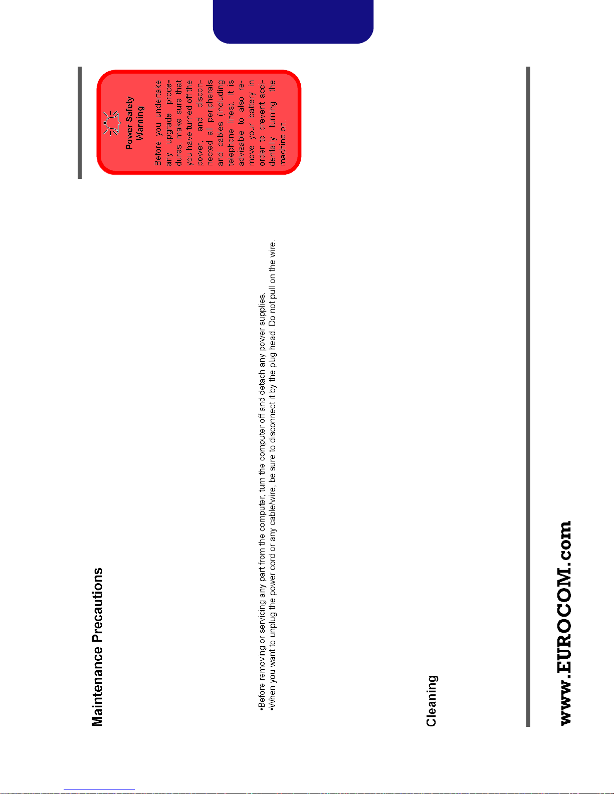
The following precautions are a reminder. To avoid personal injury or damage to the computer while performing a re-
moval and/or replacement job, take the following precautions:
1. Don't drop it. Perform your repairs and/or upgrades on a stable surface. If the computer falls, the case and other
netic fields. These can hinder proper performance and damage components and/or data. You should also monitor
2. Don't overheat it. Note the proximity of any heating elements. Keep the computer out of direct sunlight.
3. Avoid interference. Note the proximity of any high capacity transformers, electric motors, and other strong mag-
the position of magnetized tools (i.e. screwdrivers).
damaged.
4. Keep it dry. This is an electrical appliance. If water or any other liquid gets into it, the computer could be badly
5. Be careful with power. Avoid accidental shocks, discharges or explosions.
Before handling any part in the computer, discharge any static electricity inside the computer. When handling a
printed circuit board, do not use gloves or other materials which allow static electricity buildup. We suggest that
you use an anti-static wrist strap instead.
duce oils which can attract corrosive elements.
to charged surfaces, reducing performance.
screws, loose inside the computer.
6. Peripherals – Turn off and detach any peripherals.
7. Beware of static discharge. ICs, such as the CPU and main support chips, are vulnerable to static electricity.
8. Beware of corrosion. As you perform your job, avoid touching any connector leads. Even the cleanest hands pro-
9. Keep your work environment clean. Tobacco smoke, dust or other air-born particulate matter is often attracted
10. Keep track of the components. When removing or replacing any part, be careful not to leave small parts, such as
Do not apply cleaner directly to the computer, use a soft clean cloth.
Do not use volatile (petroleum distillates) or abrasive cleaners on any part of the computer.
Page 5

2.Disassembly
Disassembly
Figure 1
Battery Removal
Removing the Battery 2 - 5
4
c.
a.
1. Turn the computer off, and turn it over.
2. Loosen screws - (Figure 1a) and carefully lift the battery up (Figure 1b).
3. Remove the battery from the battery bay (Figure 1c).
3
4
2
1
b.
Page 6

Figure 8
6
5
c.
4
3
Disassembly
6
2
1
module) unsnap up the LED cover module from point on the right (Figure 8b).
1. Turn off the computer and remove the battery (page 2 - 5).
2. Remove screws - from the bottom of the computer (Figure 8a).
3. Turn the computer over, open the Lid/LCD, and carefully (a cable is connected to the underside of the LED cover
Keyboard Removal
a.
4. Disconnect cable and remove the LED cover module (Figure 8c).
b.
5
2 - 12 Removing the Keyboard
2.Disassembly
Page 7

2.Disassembly
Keyboard Removal
Disassembly
Figure 9
(cont’d.)
Removing the Keyboard 2 - 13
Keyboard Tabs
( f)
ribbon cable from the locking collar socket (Figure 9e).
5. Remove screws - from the keyboard (Figure 9d).
6. Carefully lift the keyboard up, being careful not to bend the keyboard ribbon cable . Disconnect the keyboard
7. Remove the keyboard (Figure 9f).
d. f.
7 8 9
e.
Page 8

h.
Figure 10
2
8. Remove screws - from the keyboard shielding plate (Figure 10g).
9. Lift the keyboard shielding plate up in the direction of the arrow (Figure 10h).
Keyboard
Disassembly
g.
10. Remove the keyboard shielding plate (Figure 10i).
Removal (cont’d.)
1
i.
2 - 14 Removing the Keyboard
2.Disassembly
Page 9

2.Disassembly
Figure 11
Disassembly
Insertion
Keyboard
Shielding Plate
Removing the Keyboard 2 - 15
4
5
3
b.
illustrated by arrow below, and press it down into position (Figure 11a).
1. When re-inserting the keyboard shielding plate make sure you insert it by sliding it into position at an angle as
2. Secure the plate with screws - (Figure 11b).
2
1
a.
Page 10

Figure 14
8
9
6
4
b.
7
5
3
Disassembly
2
1
arrows (Figure 14b).
The computer has three memory sockets for 204 pin Small Outline Dual In-line Memory Modules (SO-DIMM) support-
ing DDR3 1066/1333MHz. The main memory can be expanded up to 12GB. The SO-DIMM modules supported are
1024MB, and 2048MB and DDRIII Modules. The total memory size is automatically detected by the POST routine once
you turn on your computer.
Removal
RAM Module
1. Turn off the computer, remove the battery (page 2 - 5) and the keyboard (page 2 - 9).
2. The RAM modules will be visible at points - (Figure 14a).
3. Gently pull the two release latches ( - ) on the sides of the memory socket in the direction indicated by the
a.
4. The RAM module will pop-up (Figure 14c), and you can then remove it.
c.
2 - 18 Removing the System Memory (RAM)
2.Disassembly
Page 11

Disassembly
2.Disassembly
Removing the System Memory (RAM) 2 - 19
will go. DO NOT FORCE the module; it should fit without much pressure.
5. Pull the latches to release the second and third modules if necessary.
6. Insert a new module holding it at about a 30° angle and fit the connectors firmly into the memory slot.
7. The module’s pin alignment will allow it to only fit one way. Make sure the module is seated as far into the slot as it
cover).
8. Press the module in and down towards the mainboard until the slot levers click into place to secure the module.
9. Replace the bay cover and screws (make sure you reconnect the fan cable before screwing down the bay
10. Restart the computer to allow the BIOS to register the new memory configuration as it starts up.
 Loading...