

EUROCOM LP-297PB, LP295PB User Manual


I
Preface
Notice
The company reserves the right to revise this publication or to change its contents without notice. Information contained herein is for reference only and does not constitute a commitment on the part of the manufacturer or any subsequent vendor. They assume no responsibility or liability for any errors or
inaccuracies that may appear in this publication nor are they in anyway responsible for any loss or damage
resulting from the use (or misuse) of this publication.
This publication and any accompanying software may not, in whole or in part, be reproduced, translated,
transmitted or reduced to any machine readable form without prior consent from the vendor, manufacturer
or creators of this publication, except for copies kept by the user for backup purposes.
Brand and product names mentioned in this publication may or may not be copyrights and/or registered
trademarks of their respective companies. They are mentioned for identification purposes only and are not
intended as an endorsement of that product or its manufacturer.
©July 2003
Trademarks
This product incorporates copyright protection technology that is protected by method claims of certain
U.S. patents and other intellectual property rights owned by Macrovision Corporation and other rights
owners. Use of this copyright protection technology must be authorized by Macrovision Corporation, and
is intended for home or other limited viewing uses only unless otherwise authorized by Macrovision Corporation. Reverse engineering or disassembly is prohibited.
Intel and Pentium are registered trademarks of Intel Corporation.

II
Preface
FCC Statement
(Federal Communications Commission)
This equipment has been tested and found to comply with the limits for a Class B digital device, pursuant
to Part 15 of the FCC Rules. These limits are designed to provide reasonable protection against harmful
interference in a residential installation. This equipment generates, uses and can radiate radio frequency
energy and, if not installed and used in accordance with the instructions, may cause harmful interference
to radio communications. However, there is no guarantee that interference will not occur in a particular
installation. If this equipment does cause harmful interference to radio or television reception, which can
be determined by turning the equipment off and on, the user is encouraged to try to correct the interference
by one or more of the following measures:
• Re orient or relocate the receiving antenna.
• Increase the separation between the equipment and receiver.
• Connect the equipment into an outlet on a circuit different from that to which the receiver is connected.
• Consult the service representative or an experienced radio/TV technician for help.
Warning
Use only shielded cables to connect I/O devices to this equipment. You are cautioned that changes or modifications not expressly approved by the manufacturer for compliance with the above standards could void your authority to operate the equipment.

III
Preface
IMPORTANT SAFETY INSTRUCTIONS
When using your telephone equipment, basic safety precautions should always be followed to reduce the
risk of fire, electric shock and injury to persons, including the following:
1. Do not use this product near water, for example near a bath tub, wash bowl, kitchen sink or laundry
tub, in a wet basement or near a swimming pool.
2. Avoid using this equipment with a telephone line (other than a cordless type) during an electrical
storm. There may be a remote risk of electrical shock from lightning.
3. Do not use the telephone to report a gas leak in the vicinity of the leak.
4. Use only the power cord and batteries indicated in this manual. Do not dispose of batteries in a fire.
They may explode. Check with local codes for possible special disposal instructions.
CAUTION
Always disconnect all telephone lines from the wall outlet before servicing or disassembling this equipment.
TO REDUCE THE RISK OF FIRE, USE ONLY NO. 26 AWG OR LARGER,
TELECOMMUNICATION LINE CORD
IV
Preface
Instructions for Care and Operation
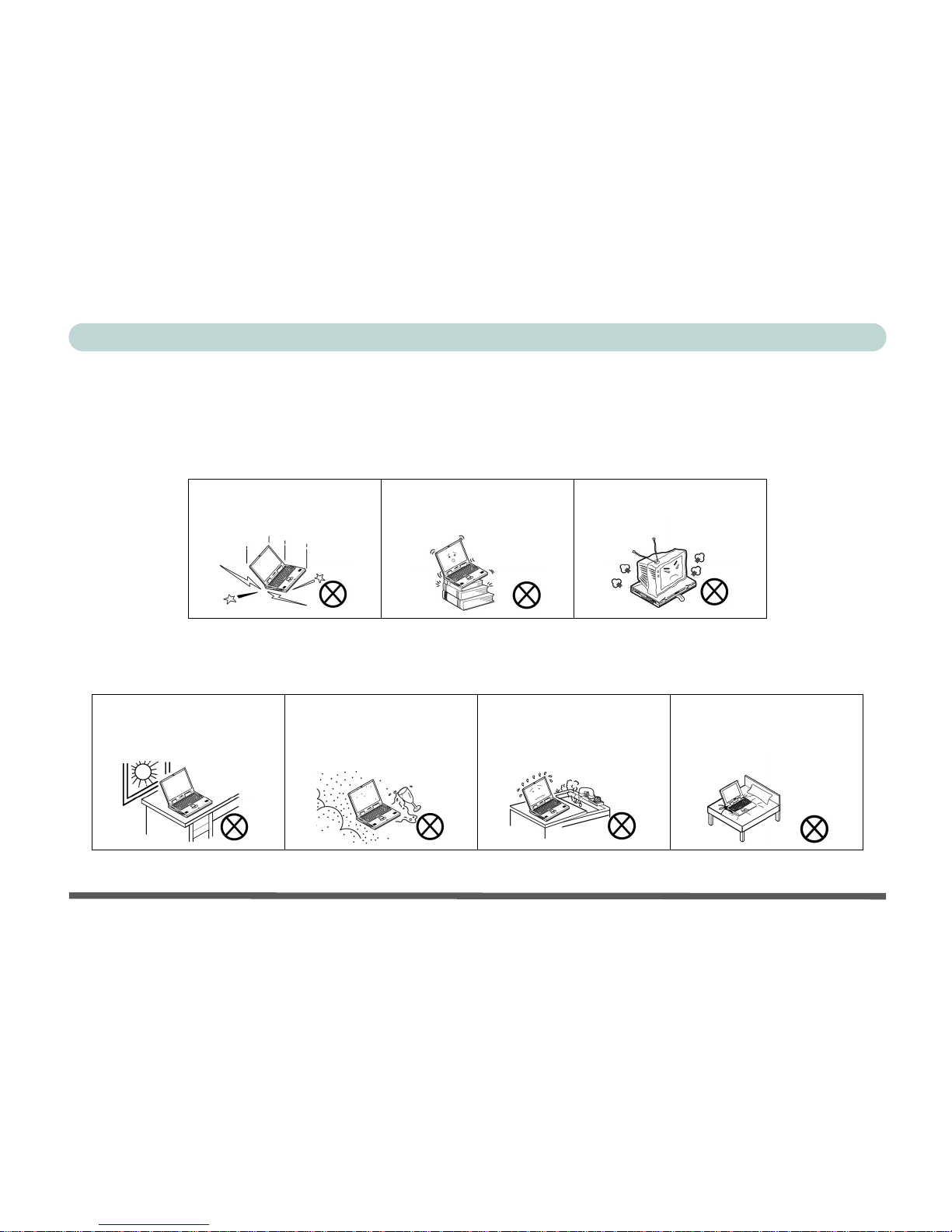
The computer is quite rugged, but it can be damaged. To prevent this, follow these suggestions:
1. Don’t drop it, or expose it to shock. If the computer falls, the case and the components could be
damaged.
2. Keep it dry, and don’t overheat it. Keep the computer and power supply away from any kind of
heating element. This is an electrical appliance. If water or any other liquid gets into it, the computer
could be badly damaged.
Do not expose the computer
to any shock or vibration.
Do not place it on an unstable
surface.
Do not place anything heavy
on the computer.
Do not expose it to excessive
heat or direct sunlight.
Do not leave it in a place
where foreign matter or moisture may affect the system.
Don’t use or store the computer in a humid environment.
Do not place the computer on
any surface which will block
the vents.
V
Preface
3. Avoid interference. Keep the computer away from high capacity transformers, electric motors, and
other strong magnetic fields. These can hinder proper performance and damage your data.
4. Follow the proper working procedures for the computer. Shut the computer down properly and
don’t forget to save your work. Remember to periodically save your data as data may be lost if the
battery is depleted.
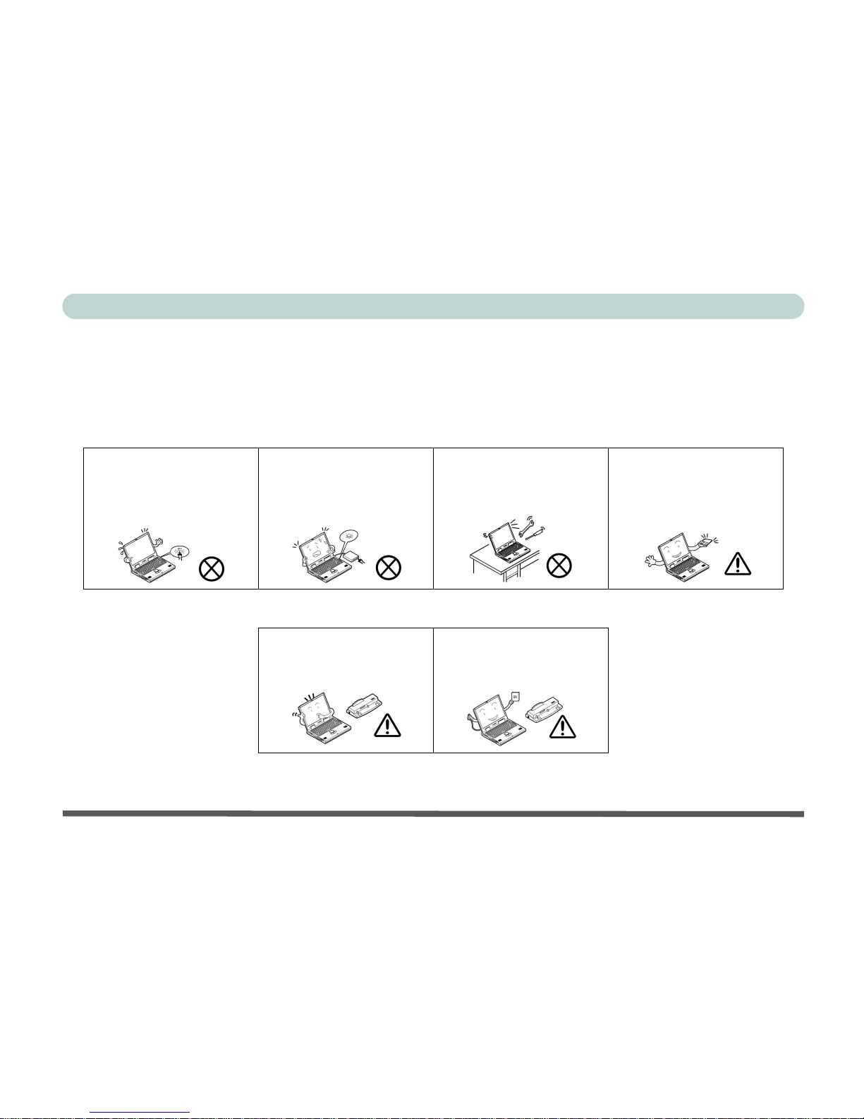
5. Take care when using peripheral devices.
Do not turn off the power
until you properly shut down
all programs.
Do not turn off any peripheral
devices when the computer is
on.
Do not disassemble the computer by yourself.
Perform routine maintenance
on your computer.
Use only approved brands of
peripherals.
Unplug the power cord before
attaching peripheral devices.
VI
Preface
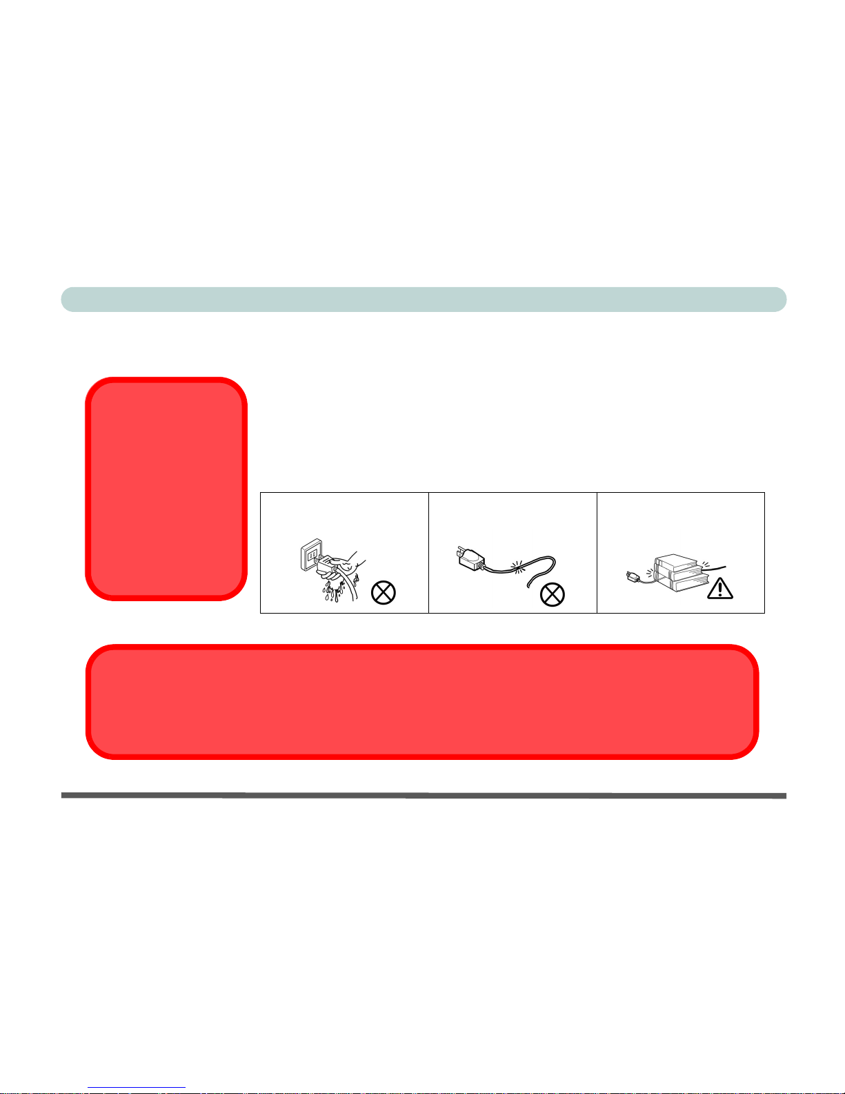
Power Safety
The computer has specific power requirements:
• When you want to unplug the power cord, be sure to disconnect it by the plug head,
not by its wire.
• Make sure the socket and any extension cord(s) you use can support the total current load of all the connected devices.
• Before cleaning the computer, make sure it is disconnected from any external
power supplies.
Do not plug in the power
cord if you are wet.
Do not use the power cord if
it is broken.
Do not place heavy objects
on the power cord.
Power Safety
Warning
Before you undertake
any upgrade procedures, make sure that
you have turned off the
power, and disconnected all peripherals
and cables (including
telephone lines).
Mainboard Battery Note
CAUTION: Danger of explosion if battery is incorrectly replaced. Replace only with the same or equivalent type
recommended by the manufacturer. Discard a used battery according to the manufacturer’s instructions.

VII
Preface
Cleaning
Do not apply cleaner directly to the computer, use a soft clean cloth.
Do not use volatile (petroleum distillates) or abrasive cleaners on any part of the computer.
Servicing
Do not attempt to service the computer yourself. Doing so may violate your warranty and expose you and
the computer to electric shock. Refer all servicing to authorized service personnel. Unplug the computer
from the power supply. Then refer servicing to qualified service personnel under any of the following conditions:
• When the power cord or AC/DC adapter is damaged or frayed.
• If the computer has been exposed to rain or other liquids.
• If the computer does not work normally when you follow the operating instructions.
• If the computer has been dropped or damaged (do not touch the poisonous liquid if the LCD panel breaks).
• If there is an unusual odor, heat or smoke coming from your computer.

VIII
Preface
Ergonomics
We designed your LCD PC system to be functional as well as attractive. To get most out of it, here are
some suggestions on how to position and use the computer:
• The top third of the LCD (screen) should be at eye-level or slightly below.
• The LCD should be at least 18"/45cm. directly in front of you.
• If the screen resolution (e.g. 1024x768) makes you strain to read, change it: In Windows Control
Panel, double-click Display (icon) and click Settings (tab). Then adjust the “Screen area” to something more comfortable (e.g. 800x600).
• Angle the LCD so that it doesn’t reflect any light into your eyes.
• Use a chair which offers good back support (especially lower-back). The seat should allow your feet
to rest flat on the floor or on a footrest directly in front of you.
• If possible, illuminate your work area with natural daylight or use a steady-glowing (non-flickering)
light source.
• Place the keyboard and mouse so that your arms are at your sides and your forearms are roughly parallel to the floor. Your wrists should flex slightly downward as you work. Your neck and shoulders
should also be relaxed.
• Take a break from the computer. Get up, stretch, flex your wrists, walk about, and look at something
else for about 10 minutes every hour.

IX
Preface
Contents
Notice ...........................................................................I
Trademarks ..........................................................I
FCC Statement ...................................................II
Instructions for Care and Operation ................. IV
Power Safety .....................................................VI
Cleaning ..........................................................VII
Servicing ..........................................................VII
Ergonomics ...........................................................I-VIII
Introduction
Overview ..................................................................1-1
In the Box .......................................................1-1
The Manual ..............................................................1-2
Advanced Users ..................................................1-2
Beginners and Not-So-Advanced Users .............1-2
Warning Boxes ...................................................1-2
Not Included .......................................................1-3
System Software .................................................1-3
Quick Start Guide .....................................................1-4
System Map ..............................................................1-5
Getting to Know Your Computer .......................1-5
Model Types and Design Differences ......................1-6
Front View ................................................................1-7
Front View ............................................................... 1-8
LCD Panel ...................................................... 1-9
Stereo Speakers .............................................. 1-9
Disk Activity LED Indicators ........................ 1-9
Power LED Indicator ..................................... 1-9
Reset Button (Model A - Design II only) ...... 1-9
Power Button ............................................... 1-10
CD Device .................................................... 1-10
Left View ............................................................... 1-11
3.5" FDD (Floppy Disk Drive) .................... 1-12
6-in-1 Flash Card Reader (Optional) ........... 1-12
Hard Disk Drive ........................................... 1-12
CD Device .................................................... 1-13
Right View ............................................................. 1-14
LCD Brightness Control Knob .................... 1-15
Volume Control Knob ................................. 1-15
Dual PC Card Slots ...................................... 1-15
Dual USB Ports ............................................ 1-16
AC Power-In Port ........................................ 1-16
Security Lock Slot ....................................... 1-16
Rear View .............................................................. 1-17
Carrying Handle ........................................... 1-18
Headphone-Out Jack .................................... 1-18
Line-In Jack ................................................. 1-18
Microphone-In Jack ..................................... 1-18

X
Preface
RJ-45 LAN Jack ...........................................1-19
RJ-11 Phone Jack .........................................1-19
Dual USB Ports ............................................1-19
Unpowered - IEEE 1394 Port .......................1-20
PS/2 Type Mouse & Keyboard Ports ...........1-20
Printer/Parallel Port ......................................1-21
Serial Port .....................................................1-21
External Monitor (CRT) Port .......................1-21
Vent ..............................................................1-21
Using The Computer
Overview ..................................................................2-1
Turning On The Computer .......................................2-2
The Disk Drives .......................................................2-3
The Hard Disk Drive (HDD) ..............................2-3
The Floppy Disk Drive (FDD) ...........................2-3
Inserting/Removing Floppy Disks .................2-3
The CD/DVD Device ...............................................2-4
Loading Compact Discs ......................................2-5
Handling CDs or DVDs ......................................2-5
DVD Regional Codes .........................................2-6
Changing the Regional Codes ........................2-7
The PC Card Slot ......................................................2-8
Inserting and Removing PC Cards .....................2-8
Keyboard ..................................................................2-9
Mouse ..................................................................... 2-10
Adding a Printer ..................................................... 2-11
USB Printer ...................................................... 2-11
Install Instructions: ...................................... 2-11
Parallel Printer .................................................. 2-12
Install Instructions: ...................................... 2-12
Advanced Controls
Overview .................................................................. 3-1
Advanced Video Controls ........................................ 3-2
Dynamic Video Memory Technology ............... 3-2
Video Driver Controls ............................................. 3-3
Making Adjustments for the Display ................. 3-3
Display Properties .............................................. 3-4
Intel Video Driver Controls .............................. 3-5
Schemes ............................................................. 3-7
Switching/Enabling Displays ................................... 3-8
Intel(R) Dual Display Clone .............................. 3-9
Power Management Features ................................. 3-10
Enabling Power Options ........................................ 3-11
Conserving Power (Individual Components) ... 3-12
Monitor Standby .......................................... 3-12
Hard Disk Standby ....................................... 3-12
Conserving Power (System) ............................. 3-13
Hibernate Mode vs. Shutdown ......................... 3-14

XI
Preface
Standby Mode vs. Hibernate Mode ..................3-14
Resuming From Power Saving Modes .............3-14
Configuring the Power Button ..........................3-15
Wireless Network Setup .........................................3-16
6-in-1 Flash Card Reader .......................................3-17
Video Capture Card ................................................3-18
Drivers & Utilities
Overview ..................................................................4-1
What To Install .........................................................4-2
Authorized Driver Message ................................4-2
Version Conflict Message ..................................4-3
Updating/Reinstalling Individual Drivers ..........4-3
Installation Procedure ...............................................4-4
Windows 2000 Professional .....................................4-5
Chipset (Win2000) .........................................4-5
Audio (Win2000) ...........................................4-6
Video (Win2000) ............................................4-6
LAN (Win2000) .............................................4-6
Modem (Win2000) .........................................4-7
Wireless LAN (Win2000) ..............................4-7
Windows XP ............................................................4-8
Chipset (WinXP) ............................................4-8
Audio (WinXP) ..............................................4-9
Video (WinXP) ..............................................4-9
LAN (WinXP) ................................................ 4-9
Modem (WinXP) ......................................... 4-10
Wireless LAN (WinXP) ............................... 4-10
BIOS Utilities
Overview .................................................................. 5-1
Important BIOS Settings .......................................... 5-2
The Power-On Self Test (POST) ............................. 5-3
POST Screen ............................................................ 5-4
Failing the POST ................................................ 5-5
Fatal Errors .................................................... 5-5
Non-Fatal Errors ............................................ 5-5
The Setup Program .................................................. 5-6
Entering Setup .................................................... 5-6
Setup Screens ..................................................... 5-6
Main Menu ............................................................... 5-7
Advanced Menu ....................................................... 5-9
Security Menu ........................................................ 5-12
Power Menu ........................................................... 5-14
Boot Menu ............................................................. 5-15
Configuring the Network Boot Protocol .......... 5-17
Exit Menu .............................................................. 5-18
Upgrading The Computer
Overview .................................................................. 6-1

XII
Preface
When Not to Upgrade .........................................6-2
Hard Disk Drive Upgrade ........................................6-3
Hard Disk Upgrade Process ................................6-3
Setting Up a New HDD ..................................6-6
System Memory Upgrade .........................................6-7
Memory Upgrade Process ..................................6-7
Troubleshooting
Overview ..................................................................7-1
Basic Hints and Tips ................................................7-2
Backup and General Maintenance ............................7-3
Viruses ......................................................................7-4
Upgrading and Adding New Hardware/Software .... 7-5
Display .....................................................................7-7
Hard Disk & Boot Password ....................................7-9
Floppy Disk Drive ..................................................7-10
Audio ......................................................................7-11
CD Device ..............................................................7-12
PC Card ..................................................................7-13
Keyboard and Mouse .............................................7-14
Printer .....................................................................7-15
Hyper-Threading Notes ..........................................7-16
Appendix A. Model A Specifications
Processor .................................................................A-1
Core Logic Chip ...................................................... A-1
BIOS ....................................................................... A-2
System Memory ...................................................... A-2
LCD ........................................................................ A-2
Video ....................................................................... A-2
Audio ...................................................................... A-3
Interface .................................................................. A-3
I/O Chip .................................................................. A-3
PC Card Sockets ..................................................... A-3
Storage .................................................................... A-3
Modem .................................................................... A-3
LAN ........................................................................ A-4
Power ...................................................................... A-4
Power Management ................................................ A-4
Indicators ................................................................ A-4
Physical Dimensions ............................................... A-4
Weight ..................................................................... A-4
Fan Bearing Type .................................................... A-4
Security ................................................................... A-4
Other Features ......................................................... A-4
Optional .................................................................. A-4
Appendix B. Model B Specifications
Processor ..................................................................B-1
Core Logic Chip .......................................................B-1

XIII
Preface
BIOS ........................................................................ B-2
System Memory ...................................................... B-2
LCD ......................................................................... B-2
Video ....................................................................... B-2
Audio ....................................................................... B-3
Interface ................................................................... B-3
I/O Chip ................................................................... B-3
PC Card Sockets ...................................................... B-3
Storage ..................................................................... B-3
Modem .................................................................... B-3
LAN ......................................................................... B-4
Power ....................................................................... B-4
Power Management ................................................. B-4
Indicators ................................................................. B-4
Physical Dimensions ...............................................B-4
Weight ..................................................................... B-4
Fan Bearing Type .................................................... B-4
Security .................................................................... B-4
Other Features ......................................................... B-4
Optional ................................................................... B-4

XIV
Preface
Overview 1 - 1
1
Introduction
Chapter 1: Introduction
Overview
What this chapter covers:
• In the Box — the parts and pieces provided
• The Manual — how to use it
• Quick Start Guide — the minimum you need to know
• System Map — navigate around your computer
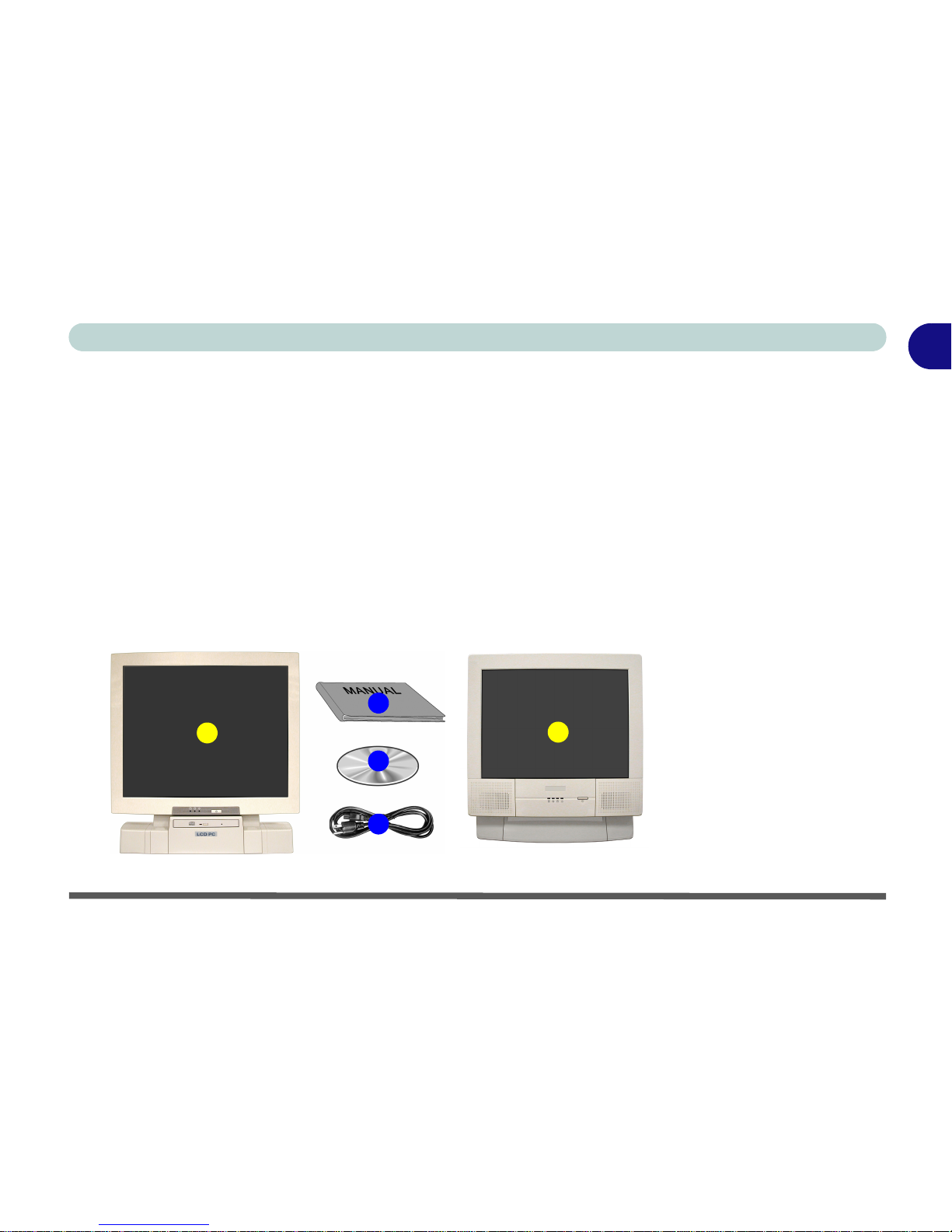
In the Box
The following should be in the box.
Figure 1 - 1
Box Contents
1. The LCD PC
(there are two different model types
in this series - see
page 1 - 6)
2. Power Cord
3. Device Driver’s &
Utilities + User’s
Manual CD-ROM
(including this
English Language
Manual in Adobe
Acrobat “PDF”
format)
4. User’s Manual
4
2
3
1
1

Introduction
1 - 2 The Manual
1
The Manual
This manual refers to the hardware and essential software required to run your
computer. Depending on how your system is configured, some or all of the
features described may already be set up.
Advanced Users
If you are an advanced user you may skip over most of this manual. However
you may find it useful to refer to the
“Drivers & Utilities” on page 4 - 1, “BI-
OS Utilities” on page 5 - 1 and
“Upgrading The Computer” on page 6 - 1.
You may find the notes marked with a
of interest to you.
Beginners and Not-So-Advanced Users
If you are new to computers, or do not have an advanced knowledge of them,
then you should try to look through all the documentation. Do not worry if you
do not understand everything the first time. Keep this manual nearby and refer
to it to learn as you go. You may find it useful to refer to the notes marked with
a
as indicated in the margin.
Warning Boxes
No matter what your level please pay careful attention to the warning and safety information indicated by the symbol. Also please note the safety and
handling instructions as indicated in the
Preface.
Notes
Check the light colored
boxes with the mark
above to find detailed
information about the
computer’s features.

The Manual 1 - 3
1
Introduction
Not Included
Operating systems (e.g. Windows 2000 Professional, Windows XP etc.) have
their own manuals as do applications (e.g. word processing, spreadsheet and
database programs). If you have questions about the operating systems or programs then please consult the appropriate manuals.
System Software
Your computer may already come with system software pre-installed. Where
this is not the case, or where you are re-configuring your computer for a different system, you will find this manual refers to the following operating systems:
• Microsoft Windows 2000 Professional
• Microsoft Windows XP

Introduction
1 - 4 Quick Start Guide
1
Quick Start Guide
This guide assumes that you are already familiar with computers and can tell
at a glance what and where all the key components are. If you are not that comfortable with this type of device, then please refer to the following pages,
which give an overview of the system.
It is still best to review these steps, before taking any action. If there is anything you are not sure about, then please refer to the appropriate chapter before
continuing.
Unless you need to install an operating system your computer should be ready
to work right out of the box. Before you begin please follow the safety instructions in the Preface.
1. Remove all packing materials, CDs/DVDs, floppy disks, and any Pc Cards.
2. Securely attach any peripherals you want to use with the computer (e.g.
keyboard and mouse) to their ports.
3. Attach the AC power cord to the AC power-In port on the right of the
computer.
Then plug the AC power cord into an outlet.
4. Push the power button to turn the computer “on”.
Peripheral Devices
Please note that peripherals (printers, digital cameras, etc.)
which attach to your
computer by either
USB or IEEE1394
ports may be connected after Windows is
up and running. All other peripherals must be
connected before you
turn on the system.

System Map 1 - 5
1
Introduction
System Map
Your LCD PC has a lot of built-in features. Most of these are enabled by your
operating system (OS). Further explanations of the various subsystems are
covered in the chapter or pages indicated.
Getting to Know Your Computer
The following graphics will help you to become familiar with the basic functions, and to learn the location of the various ports and components of your
computer.
Introduction
1 - 6 Model Types and Design Differences
1
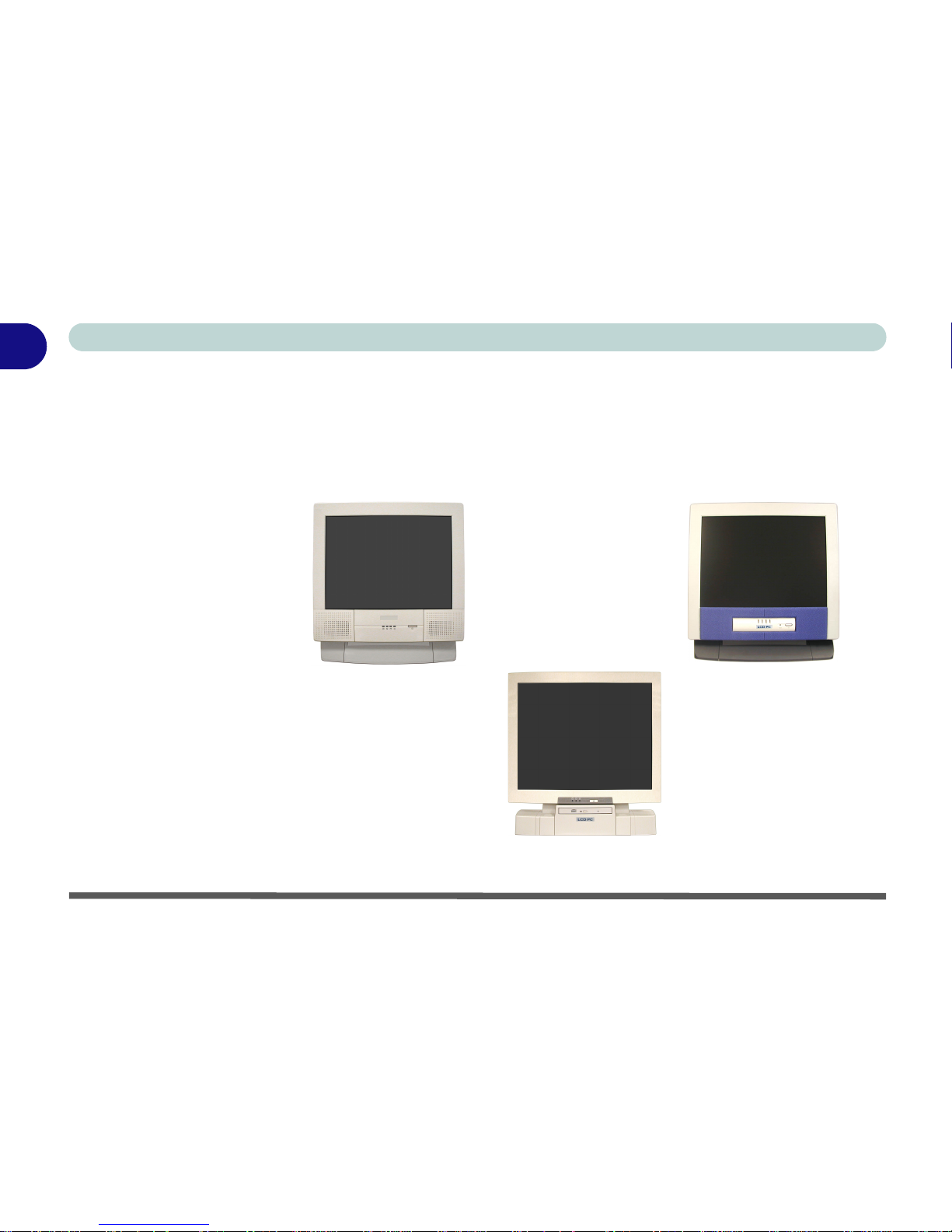
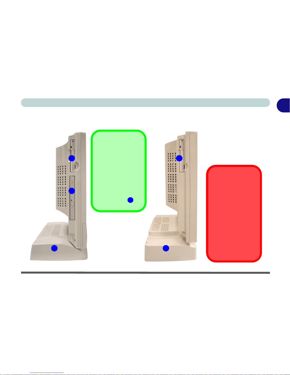
Model Types and Design Differences
There two model types (pictured below) in this LCD PC series. The model
types differ in physical appearance (Model A’s CD device is located on the
left side of the computer, Model B’s is at the front) and their specifications.
In addition, Model A has two different designs.
Figure 1 - 2
Model Types &
Design Differences
Model A (Design I) Model A (Design II)
Model B
Front View 1 - 7
1
Introduction
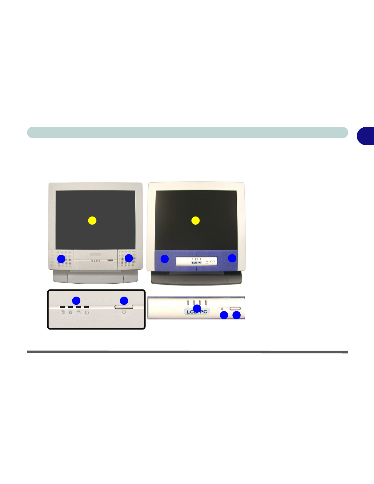
Front View
(Model A)
2
43
1
2
Design I Design II
2
4
3
5
1
2
Figure 1 - 3
Front View (Model A)
1. LCD Panel
2. Speakers
3. LED Activity
indicators
4. Power Button
5. Reset Button
(Design II only)
Introduction
1 - 8 Front View
1
Front View
(Model B)
Figure 1 - 4
Front View (Model B)
1. LCD Panel
2. Speakers
3. LED Activity
indicators
4. Power Button
5. CD Device
5
3 4
1
22
Front View 1 - 9
1
Introduction
LCD Panel
The LCD PC comes with a 15" XGA or 17" SXGA LCD (Liquid Crystal Display) TFT color screen (see “LCD” on pages A-2 and B-2 for details).
Stereo Speakers
The built-in speakers provide rich, stereo sound.
Disk Activity LED Indicators
These display the system’s operational status including the power status, and
read/write activity on the floppy disk drive, hard disk drive and CD device
(Model A has a separate indicator for CD activity , Model B uses a single
indicator for CD and HDD activity.)
Power LED Indicator
When the system is powered on and the operating system running the light
will be solid green. When the system is in the Standby power saving mode,
the light will flash orange. When the system is in Hibernate power saving
mode the light will be off (see “Configuring the Power Button” on page 3 -
15).
Reset Button (Model A - Design II only)
Press this button to restart your computer. This button is equivalent to pressing
Ctrl + Alt + Del and only available on Model A - Design II (Figure 1 - 3).

Introduction
1 - 10 Front View
1
Power Button
Press this button to turn your computer on or off (see “Turning On The Com-
puter” on page 2 - 2).
This button may also be used as a suspend/resume key,
once configured as such, in the power management control panel of your operating system (see “Configuring the Power Button” on page 3 - 15). The
power LED will display the current power status of the computer.
CD Device
A CD-ROM drive, DVD-ROM drive, CD-RW drive, or Combination CD-RW
and DVD-ROM, or DVD/RW+R drive (12.7mm height) is standard depending on the model you purchased. For more information on using the drive
please refer to “The CD/DVD Device” on page 2 - 4.
Shutdown
Please note that you
should always shut
your computer down
by choosing the Shut
Down/Turn Off Computer command from
the Start menu in Windows. This will help
prevent hard disk or
system problems.
Forced Off
If the system “hangs”,
and the Ctrl + Alt + Del
key combination
doesn’t work, press the
power button for 4 sec-
onds to force the system to turn itself off.
CD Emergency Eject
If you need to manually eject a CD/DVD (e.g. due to an unexpected power interruption) you may push the end of a straightened paper clip into the emergency eject
hole. Do not use a sharpened pencil or similar object that may break and become
lodged in the hole.
Left View 1 - 11
1
Introduction
Left View
Drive Warning
Don’t try to remove the
hard disk (HDD) while
the system is on. This
could cause data loss
or damage.
Unauthorized removal
or tampering with the
HDD may violate your
warranty. If you are in
doubt, consult your
service representative.
Figure 1 - 5
Left View
1. Floppy Disk Drive*
2. Hard Disk Drive
(HDD) Bay
3. CD Device (Model
A only)
1
2
1
2
3
Model BModel A
*Floppy Disk Drive &
Optional Modules
If you have either the
6-in-1 Card Reader,
or Video Capture
Card options, then
the optional module
will replace the floppy
disk drive module in
the slot at point .
1

Introduction
1 - 12 Left View
1
3.5" FDD (Floppy Disk Drive)
This is a 3.5", 3-mode, 1.44 MB fixed floppy disk drive. For more information
please refer to “The Floppy Disk Drive (FDD)” on page 2 - 3.
6-in-1 Flash Card Reader (Optional)
The card reader allows you to use the most popular digital storage cards. The
formats which can be read include:
• MMC (MultiMedia Card)
• SD (Secure Digital)
• MS (Memory Stick)
• SM (SmartMedia Card)
• CF (Compact Flash Types I & II)
• MD (IBM Microdrive)
Video Capture Card (Optional)
The video capture card allows you to watch TV, video conference and capture
still images and video on your PC. The card has an S-Video-In port and Audio/
Video ports.
Hard Disk Drive
See “Hard Disk Drive Upgrade” on page 6 - 3 for information on upgrading/
replacing your hard disk drive (see “Storage” on page A - 3).
Media Warning
Don’t try to remove a
floppy disk while the
system is accessing it.
This may cause the
system to “crash”.
*Floppy Disk Drive &
Optional Modules
If you have either the
6-in-1 Card Reader,
or Video Capture
Card options, then
the optional module
will replace the floppy
disk drive module in
the slot at point .
1

Left View 1 - 13
1
Introduction
CD Device
A CD-ROM drive, DVD-ROM drive, CD-RW drive, Combination CD-RW
and DVD-ROM drive, or DVD/RW+R drive (12.7mm height) is standard depending on the model you purchased. For more information on using the drive
please refer to “The CD/DVD Device” on page 2 - 4.
CD Emergency Eject
If you need to manually eject a CD/DVD (e.g. due to an unexpected power interruption) you may push the end of a straightened paper clip into the emergency eject
hole. Do not use a sharpened pencil or similar object that may break and become
lodged in the hole.
Introduction
1 - 14 Right View
1
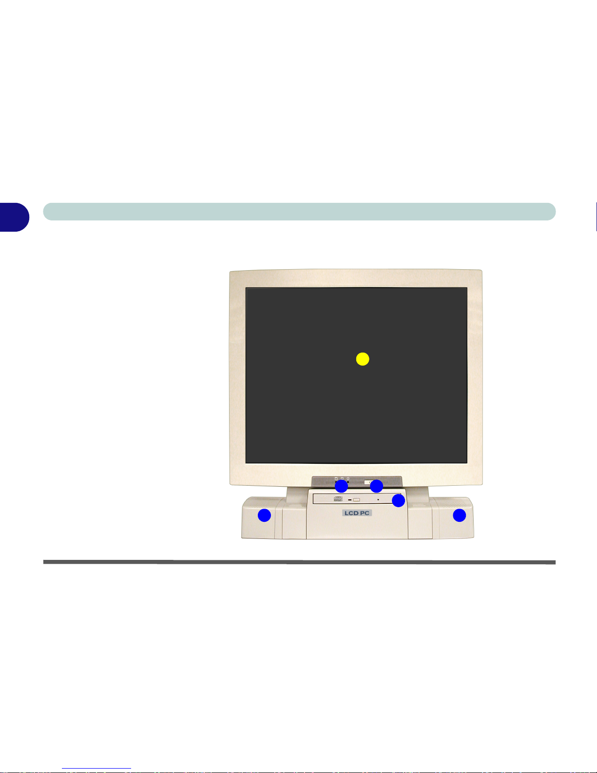
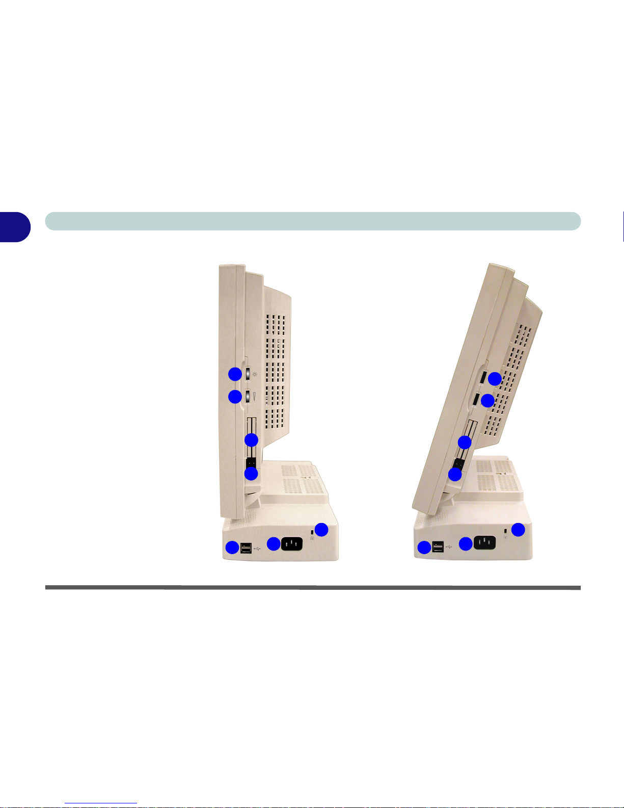
Right View
Figure 1 - 6
Right View (All
Models)
1. LCD Brightness
Control Knob
2. Volume Control
Knob
3. Dual PC Card
Slots
4. PC Card Eject
Buttons
5. Dual USB Ports
6. AC Power-In Port
7. Security Lock Slot
4
7
6
5
3
1
2
4
7
6
5
3
1
2
 Loading...