

Page 1

Page 2

Preface
I
Notice
The company reserves the right to revise this publication or to
change its contents without notice. Information contained herein is
for reference only and does not constitute a commitment on the part
of the manufacturer or any subsequent vendor. They assume no responsibility or liability for any errors or inaccuracies that may appear
in this publication nor are they in anyway responsible for any loss or
damage resulting from the use (or misuse) of this publication.
This publication and any accompanying software may not, in whole
or in part, be reproduced, translated, transmitted or reduced to any
machine readable form without prior consent from the vendor, manufacturer or creators of this publication, except for copies kept by the
user for backup purposes.
Brand and product names mentioned in this publication may or may
not be copyrights and/or registered trademarks of their respective
companies. They are mentioned for identification purposes only and
are not intended as an endorsement of that product or its
manufacturer.
©July 2002
Page 3

Preface
II
Trademarks
This product incorporates copyright protection technology that is
protected by method claims of certain U.S. patents and other intellectual property rights owned by Macrovision Corporation and other
rights owners. Use of this copyright protection technology must be
authorized by Macrovision Corporation, and is intended for home or
other limited viewing uses only unless otherwise authorized by Macrovision Corporation. Reverse engineering or disassembly is prohibited.
Intel and Pentium are registered trademarks of Intel Corporation.
MS-DOS and Windows are registered trademarks of Microsoft Cor-
poration.
Page 4

Preface
III
Federal Communications Commission (FCC)
Statement
This equipment has been tested and found to comply with the limits
for a Class B digital device, pursuant to Part 15 of the FCC Rules.
These limits are designed to provide reasonable protection against
harmful interference in a residential installation. This equipment
generates, uses and can radiate radio frequency energy and, if not installed and used in accordance with the instructions, may cause
harmful interference to radio communications. However, there is no
guarantee that interference will not occur in a particular installation.
If this equipment does cause harmful interference to radio or television reception, which can be determined by turning the equipment
off and on, the user is encouraged to try to correct the interference by
one or more of the following measures:
• Re orient or relocate the receiving antenna.
• Increase the separation between the equipment and receiver.
• Connect the equipment into an outlet on a circuit different from that to
which the receiver is connected.
• Consult the service representative or an experienced radio/TV technician for help.
Warning
Use only shielded cables to connect I/O devices to this equipment.
You are cautioned that
changes or modifications not expressly approved by the
manufacturer for compliance with the above
standards could void
your authority to operate
the equipment.
Page 5

Preface
IV
IMPORTANT SAFETY INSTRUCTIONS
When using your telephone equipment, basic safety precautions
should always be followed to reduce the risk of fire, electric shock
and injury to persons, including the following:
1. Do not use this product near water, for example near a bath tub, wash
bowl, kitchen sink or laundry tub, in a wet basement or near a swimming pool.
2. Avoid using a telephone (other than a cordless type) during an
electrical storm. There may be a remote risk of electrical shock from
lightning.
3. Do not use the telephone to report a gas leak in the vicinity of the leak.
4. Use only the power cord and batteries indicated in this manual. Do not
dispose of batteries in a fire. They may explode. Check with local
codes for possible special disposal instructions.
CAUTION
Always disconnect all telephone lines from the wall outlet before
servicing or disassembling this equipment.
USE THE APPROPRIATE 26AGW TELEPHONE
LINE CORD
Page 6

Preface
V
IMPORTANTES MESURES DE SÉCURITÉ
Certaines mesures de sécurité doivent être prises pendant l’utilisation de matérial téléphonique afin de réduire les risques d’incendie,
de choc électrique et de blessures. En voici quelquesunes:
1. Ne pas utiliser l’appareil près de l’eau,, p.ex., près d’une baignoire,
d’un lavabo, d’un évier de cuisine, d’un bac à laver, dans un sous-sol
humide ou près d’une piscine.
2. Éviter d’utiliser le téléphone (sauf s’il s’agit d’un appareil sans fil) pendant un orage électrique. Ceci peut présenter un risque de choc électrique causé par la foudre.
3. Ne pas utiliser l’appareil téléphonique pour signaler une fuite de gaz
s’il est situé près de la fuite.
4. Utiliser seulement le cordon d’alimentation et le type de piles indiqués
dans ce manuel. Ne pas jeter les piles dans le feu: elles peuvent
exploser. Se conformer aux règlements pertinents quant à l’émination
des piles.
ATTENTION
Débranchez toujours toutes les lignes téléphoniques des prises murales avant de réparer ou de démonter cet équipement.
UTILISEZ LE CORDON DE TÉLÉPHONE 26AGW
APPROPRIÉ
Page 7

Preface
VI
Instructions for Care and Operation
The computer is quite rugged, but it can be damaged. To ensure that
does not happen, follow these suggestions:
1. Don’t drop it. Make sure it’s on a stable surface. If the compu-
ter falls, the case and other components could be damaged. Do
not expose it to any shock or vibration.
2. Don’t overheat it. Keep the computer and power supply away
from any kind of heating element. Keep the computer out of
direct sunlight. Don’t store or use the computer in a humid
environment. Do not place the computer on any surface which
will block the vents.
3. Avoid interference. Keep the computer away from high
capacity transformers, electric motors, and other strong
magnetic fields. These can hinder proper performance and
damage your data.
4. Keep it dry. This is an electrical appliance. If water or any other
liquid gets into it, the computer could be badly damaged. Do not
leave it in a place where foreign matter or moisture may affect
the system.
Page 8

Preface
VII
5. Follow the proper working procedures for computer.
Shutdown the computer properly, and close all programs (don’t
forget to save your work). Do not turn off any peripheral devices
when the computer is on. Do not disassemble the computer by
yourself. Remember to periodically save your data as data may
be lost if the battery is depleted. Perform routine maintenance
on your computer.
6. Take care when using peripheral devices. Use only approved
brands of peripheral devices. Unplug the power cord before
attaching any peripheral device.
7. Do not place anything heavy on the computer.
Page 9

Preface
VIII
Power Safety
The computer has specific power requirements:
• When you want to unplug the power cord, be sure to disconnect it by
the plug head, not by its wire.
• Make sure the socket and any extension cord(s) you use can support
the total current load of all the connected devices.
• Before cleaning the computer, make sure it is disconnected from any
external power supplies.
• Do not plug in the power cord if you are wet.
• Do not use the power cord if it is broken.
• Do not place heavy objects on the power cord.
Page 10

Preface
IX
Servicing
Do not attempt to service the computer yourself. Doing so may violate your warranty and expose you and the computer to electric
shock. Refer all servicing to authorized service personnel. Unplug
the computer from the power supply. Then refer servicing to qualified service personnel under any of the following conditions:
• When the power cord is damaged or frayed.
• If the computer has been exposed to rain or other liquids.
• If the computer does not work normally when you follow the operating
instructions.
• If the computer has been dropped or damaged (do not touch the poisonous liquid if the LCD panel breaks).
• If there is an unusual odor, heat or smoke coming from your computer.
Page 11

Preface
X
Cleaning
Do not apply cleaner directly to the computer, use a soft clean cloth.
Do not use volatile (petroleum distillates) or abrasive cleaners on any
part of the computer.
Page 12

Preface
XI
Contents
Introduction ........................................... 1-1
Overview ..................................................................................... 1-1
In the Box .................................................................................... 1-2
The Manual ................................................................................. 1-3
Advanced Users ...................................................................... 1-3
Beginners and Not-So-Advanced Users ................................. 1-3
Warning Boxes ....................................................................... 1-4
Not Included ................................................................................ 1-5
System Software ..................................................................... 1-5
Quick Start Guide ........................................................................ 1-6
System Map ................................................................................. 1-7
Getting To Know Your Computer .......................................... 1-7
Front View ................................................................................... 1-8
LCD Panel .......................................................................... 1-9
Stereo Speakers .................................................................. 1-9
LED Disk Activity Indicators ............................................ 1-9
LED Power Indicator ......................................................... 1-9
Power Button ................................................................... 1-10
Reset Button ..................................................................... 1-10
Page 13

Preface
XII
Left View ...................................................................................1-11
3.5” FDD (Floppy Disk Drive) ........................................1-12
Hard Disk Drive ...............................................................1-12
CD Device ........................................................................1-12
Right View .................................................................................1-13
LCD Brightness Control Knob ......................................... 1-14
Volume Control Knob ......................................................1-14
Dual PC Card Slots ..........................................................1-14
Dual USB Ports ...............................................................1-15
AC Power-In Port .............................................................1-15
Security Lock Slot ............................................................1-15
Rear View .................................................................................. 1-16
Carrying Handle ...............................................................1-17
Headphone-Out Jack ........................................................1-17
Line-In Jack ......................................................................1-17
Microphone-In Jack ..........................................................1-17
RJ-45 LAN Jack ...............................................................1-18
RJ-11 Phone Jack ............................................................. 1-18
Dual USB Ports ...............................................................1-18
Unpowered - IEEE 1394 Port ...........................................1-19
PS/2 Type Mouse & Keyboard Ports ...............................1-19
Printer/Parallel Port ..........................................................1-20
Page 14

Preface
XIII
Serial Port ........................................................................ 1-20
External Monitor (CRT) Port ........................................... 1-20
Vent .................................................................................. 1-20
Using The Computer ............................. 2-1
Overview ..................................................................................... 2-1
Ergonomics .................................................................................. 2-2
Turning On The Computer .......................................................... 2-4
The Disk Drives .......................................................................... 2-5
The Hard Disk Drive (HDD) .................................................. 2-5
The Floppy Disk Drive (FDD) ............................................... 2-5
Inserting/Removing Floppy Disks ..................................... 2-5
The CD/DVD Device .................................................................. 2-6
Loading Compact Discs ......................................................... 2-6
Handling CD's or DVD's ........................................................ 2-7
DVD Regional Codes ............................................................. 2-8
To Change the Regional Codes ......................................... 2-9
The PC Card Slot ....................................................................... 2-10
Inserting And Removing PC Cards ...................................... 2-10
Keyboard ................................................................................... 2-11
Mouse ........................................................................................ 2-12
Adding a Printer ........................................................................ 2-13
Page 15

Preface
XIV
USB Printer ........................................................................... 2-13
Install Instructions: ...........................................................2-13
Parallel Printer ......................................................................2-14
Install Instructions: ...........................................................2-14
Advanced Controls ................................3-1
Overview ......................................................................................3-1
Advanced Video Controls ............................................................3-2
Video Driver Controls .................................................................3-2
Making Adjustments For The LCD ........................................ 3-3
Display Properties .............................................................. 3-4
SiS Utility Tray/Manager ........................................................ 3-5
Video Memory .............................................................................3-7
Display Devices ...........................................................................3-8
Display Options ...........................................................................3-9
Mirror Mode ............................................................................3-9
Multimonitor Mode ............................................................... 3-10
Switching/Enabling Displays (Driver Controls) ................... 3-12
Attaching a Monitor (CRT) .......................................................3-14
Power Management Features ..................................................... 3-15
Advanced Configuration and Power Interface (ACPI) ......... 3-15
Enabling Power Options ............................................................3-16
Page 16

Preface
XV
Conserving Power Through Individual Components ........... 3-17
Monitor Standby .............................................................. 3-17
Hard Disk Standby ........................................................... 3-17
Conserving Power Throughout the Whole System .............. 3-18
Hibernate Mode vs. Shutdown ............................................. 3-19
Standby Mode vs. Hibernate Mode ...................................... 3-19
Configuring the Power Button .............................................. 3-20
Resuming From Power Saving Modes ................................. 3-21
Drivers & Utilities ................................. 4-1
Overview ..................................................................................... 4-1
What To Install ............................................................................ 4-2
Authorized Driver Message .................................................... 4-3
Version Conflict Message ...................................................... 4-3
Installation Procedure .................................................................. 4-3
Windows 2000 Professional ........................................................ 4-4
Audio (Win2000) .................................................................... 4-4
Video (Win2000) .................................................................... 4-5
LAN (Win2000) ..................................................................... 4-5
Modem (Win2000) ................................................................. 4-5
Wireless LAN (Win2000) ...................................................... 4-6
USB 2.0 (Win2000) ................................................................ 4-6
Page 17

Preface
XVI
Windows XP ................................................................................ 4-7
Audio (WinXP) ....................................................................... 4-7
Video (WinXP) ....................................................................... 4-8
LAN (WinXP) ......................................................................... 4-8
Modem (WinXP) ....................................................................4-8
Wireless LAN (WinXP) .......................................................... 4-9
USB 2.0 (WinXP) ................................................................... 4-9
BIOS Utilities .........................................5-1
Overview ......................................................................................5-1
Important BIOS Settings ..............................................................5-2
The Power-On Self Test (POST) ................................................. 5-3
POST Screen ................................................................................ 5-4
Failing the POST .....................................................................5-5
Fatal Errors .........................................................................5-5
Non-Fatal Errors ................................................................. 5-5
Choosing the Boot Device Before OS Startup ........................ 5-6
The Setup Program ......................................................................5-7
Entering Setup ......................................................................... 5-7
Setup Screens ..........................................................................5-7
Main Menu ...................................................................................5-8
Advanced Menu .........................................................................5-10
Page 18

Preface
XVII
Security Menu ........................................................................... 5-13
Boot Menu ................................................................................. 5-15
Exit Menu .................................................................................. 5-17
Upgrading The Computer .................... 6-1
Overview ..................................................................................... 6-1
When Not to Upgrade ............................................................. 6-2
Hard Disk Drive Upgrade ........................................................... 6-3
Upgrading The Hard Disk ...................................................... 6-3
Some Things to Watch Out For .............................................. 6-6
Software ............................................................................. 6-6
Setting Up a New HDD ..................................................... 6-6
System Memory Upgrade ............................................................ 6-7
Upgrading the Memory .......................................................... 6-7
Troubleshooting ..................................... 7-1
Overview ..................................................................................... 7-1
Basic Hints and Tips ................................................................... 7-2
Backup and General Maintenance ............................................... 7-4
Viruses ......................................................................................... 7-5
Upgrading and Adding New Hardware/Software ....................... 7-6
Display ........................................................................................ 7-8
Page 19

Preface
XVIII
Hard Disk Drive (HDD) ............................................................7-12
Boot Password ...........................................................................7-12
Floppy Disk Drive (FDD) .......................................................... 7-13
Audio .........................................................................................7-14
CD Device .................................................................................7-15
PC Card ...................................................................................... 7-18
Keyboard and Mouse ................................................................. 7-19
Printer ........................................................................................7-20
Glossary ................................................ G-1
Appendix A. Specifications ..................A-1
Processor .....................................................................................A-1
Core Logic Chip .........................................................................A-2
BIOS ...........................................................................................A-2
System Memory .......................................................................... A-2
Video ...........................................................................................A-2
LCD ............................................................................................A-3
Audio ..........................................................................................A-3
Interface ...................................................................................... A-3
PC Card Sockets .........................................................................A-4
Storage ........................................................................................A-4
Page 20

Preface
XIX
Modem ....................................................................................... A-4
LAN ............................................................................................ A-4
Power .......................................................................................... A-4
Power Management .................................................................... A-5
Support for WFM Ver 2.0 .......................................................... A-5
Indicators .................................................................................... A-5
Physical Dimensions .................................................................. A-5
Weight ........................................................................................ A-5
Fan Bearing Type: ...................................................................... A-5
Security ....................................................................................... A-5
Optional ...................................................................................... A-6
Page 21

Preface
XX
Page 22

Introduction
Overview 1 - 1
1
Chapter 1: Introduction
Overview
What this chapter covers:
• In the Box — the parts and pieces provided
• The Manual — how to use it
• Quick Start Guide — the minimum you need to know
• System Map — navigate around your computer
Page 23
Introduction
1-2In the Box
1
In the Box
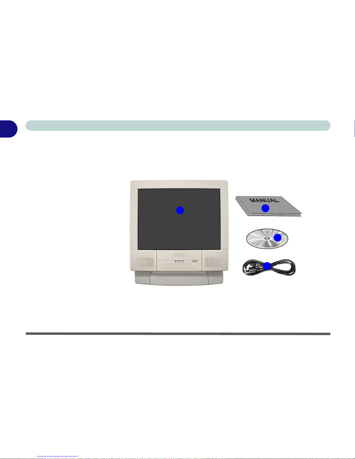
The following should be in the box.
Figure 1 - 1
Box Contents
4
2
1
3
1. The LCD PC
2. Power Cord
3. Device Driver’s &
Utilities & User’s
Manual CD ROM
(including this
manual in Adobe
Acrobat “PDF”
format)
4. User’s Manual
Page 24

Introduction
The Manual 1 - 3
1
The Manual
This manual refers to the hardware and essential software required to
run your computer. Depending on how your system is configured,
some or all of the features described may already be set up.
Advanced Users
If you are an advanced user you may skip over most of this manual.
However you may find it useful to refer to the “Drivers & Utilities”
on page 4 - 1, “BIOS Utilities” on page 5 - 1 and “Upgrading The
Computer” on page 6 - 1. You may also find the notes marked with
a of interest to you.
Beginners and Not-So-Advanced Users
If you are new to computers, or do not have an advanced knowledge
of them, then you should try to look through all the documentation.
Do not worry if you do not understand everything the first time. Keep
this manual nearby and refer to it to learn as you go. You may find it
useful to refer to the notes marked with a as indicated in the margin.
Notes
Check the light colored
boxes with the mark
above.
This is where you will
find detailed information
about the computer’s
features.
Beginners may refer to
this area also, and you
may be surprised how
much you understand.
Page 25

Introduction
1 - 4 The Manual
1
Warning Boxes
No matter what your level please pay careful attention to the warning
and safety information indicated by the symbol. Also please note
the safety and handling instructions as indicated in the Preface.
Page 26

Introduction
Not Included 1 - 5
1
Not Included
Operating Systems (e.g. Windows 2000 Professional, Windows XP
etc.) have their own manuals as do applications (e.g. word process-
ing, spreadsheet and database programs). If you have questions
about the operating systems or programs then please consult the appropriate manuals.
System Software
Your computer may already come with system software pre-installed. Where this is not the case, or where you are re-configuring
your computer for a different system, you will find this manual refers
to the following operating systems:
• Microsoft Windows 2000
• Microsoft Windows XP
Page 27

Introduction
1 - 6 Quick Start Guide
1
Quick Start Guide
This guide assumes that you are already familiar with computers and
can tell at a glance what and where all the key components are. If you
are not that comfortable with this type of device, then please refer to
the following pages, which give an overview of the system.
It is still best to review these steps, before taking any action. If there
is anything you are not sure about, then please refer to the appropriate chapter before continuing.
Unless you need to install an operating system your computer should
be ready to work right out of the box. Before you begin please follow
the safety instructions in the Preface.
1. Remove all packing materials, CD/DVDs, floppy disks, and any
PC Cards.
2. Securely attach any peripherals you want to use with the
computer (e.g. keyboard and mouse) to their ports.
3. Attach the AC power cord to the AC Power-In Port on the right
of the computer.
Then plug the AC power cord into an outlet.
4. Push the power button to turn the computer “on”.
Page 28

Introduction
System Map 1 - 7
1
System Map
Your LCD PC has a lot of built-in features. Most of these are enabled
by your operating system (OS). Further explanations of the various
subsystems are covered in the chapter or pages indicated.
Getting To Know Your Computer
The following graphics will help you to become familiar with the basic functions, and to learn the location of the various ports and components of your computer.
Peripheral Devices
Please note that peripherals (printers, digital
cameras, etc.) which attach to your computer
by either USB or
IEEE1394 ports may be
connected after Windows is up and running.
All other peripherals
must be connected be-
fore you turn on the system.
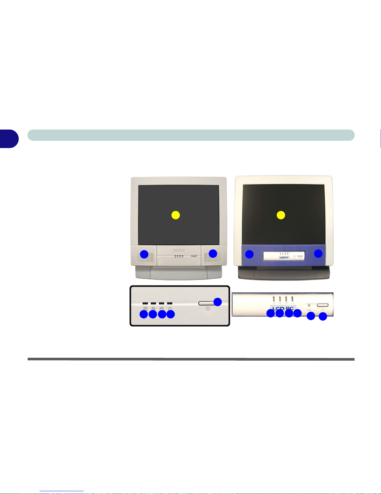
Model Differences
This manual refers to two LCD PC models pictured on Figure 1 - 2 on page
1-8. The models vary slightly in external design. Photographs used through-
out this manual are of Model I.
Page 29
Introduction
1 - 8 Front View
1
Front View
2
7
5
6
3 4
1
2
Model I Model II
2
7
5
6
3 4
1
2
8
Figure 1 - 2
Front View
1. LCD Panel
2. Speakers
3. FDD Activity LED
4. CD Device
Activity LED
5. HDD Activity
LED
6. Power LED
7. Power Button
8. Reset Button
(Model II only)
Page 30

Introduction
Front View 1 - 9
1
LCD Panel
The LCD PC comes with a 15” LCD (Liquid Crystal Display)
screen.
Stereo Speakers
The built-in speakers provide rich, stereo sound.
LED Disk Activity Indicators
These display the system’s operational status including the power
status, and read/write activity on the floppy disk drive, hard disk
drive and CD Device.
LED Power Indicator
When the system is powered on, and the operating system running,
the light will be solid green. When the system is in Standby mode,
the light will flash orange. When the System is in Hibernate mode,
the light will be off (“Configuring the Power Button” on page 3 -
20).
Page 31

Introduction
1 - 10 Front View
1
Power Button
Press this button to turn your computer on or off (“Turning On The
Computer” on page 2 - 4). This button may also be used as a sus-
pend/resume key, once configured as such, in the power options control panel of your operating system (“Configuring the Power
Button” on page 3 - 20).
Reset Button
Press this button to restart your computer. This button is equivalent
to pressing Ctrl + Alt + Del and only available on Model II (Figure
1 - 2).
Shutdown
Please note that you
should always shut your
computer down by
choosing the Shut
Down/Turn Off Computer command from
the Start menu in Windows. This will help pre-
vent hard disk or system
problems.
Forced Off
If the system “hangs”, and the Ctrl + Alt + Del key combination doesn’t work,
press the power button for 4 seconds to force the system to turn itself off.
Page 32

Introduction
Left View 1 - 11
1
Left View
Figure 1 - 3
Left View
1. Floppy Disk
Drive
2. CD Device
3. Hard Disk Drive
(HDD) Bay
4. CD Emergency
Eject Hole
Media Warning
Don’t try to remove a
floppy disk while the
system is accessing it.
This may cause the system to “crash”.
CD Emergency Eject
If you need to manually
eject a CD/DVD (e.g.
due to an unexpected
power interruption) you
may push the end of a
straightened paper clip
into the emergency eject
hole.
Do not use a sharpened
pencil or similar object
that may break and become lodged in the hole.
1
4
3
1
2
3
2
Page 33

Introduction
1 - 12 Left View
1
3.5” FDD (Floppy Disk Drive)
This is a 3.5”, 3-mode, 1.44 MB fixed floppy disk drive. For more
information please refer to “The Floppy Disk Drive (FDD)” on
page 2 - 5.
Hard Disk Drive
Please see “Hard Disk Drive Upgrade” on page 6 - 3 for information on upgrading/replacing your hard disk drive (“Storage” on
page A - 4).
CD Device
A CD-ROM drive, OR DVD-ROM drive, OR CD-RW drive, OR
Combination CD-RW and DVD-ROM drive (12.7mm height) is
standard depending on the model you purchased. For more information on using the drive please refer to “The CD/DVD Device” on
page 2 - 6.
Drive Warning
Don’t try to remove the
hard disk (HDD) while
the system is on. This
could cause data loss or
damage.
Unauthorized removal
or tampering with the
HDD may violate your
warranty. If you are in
doubt, consult your
service representative.
Page 34

Introduction
Right View 1 - 13
1
Right View
Figure 1 - 4
Right View
1. LCD Brightness
Control Knob
2. Volume Control
Knob
3. Dual PC Card
Slots
4. PC Card Eject
Buttons
5. Dual USB Ports
6. AC Power-In Port
7. Security Lock
Slot
2
4
7
6
5
1
3
1
2
Page 35

Introduction
1 - 14 Right View
1
LCD Brightness Control Knob
Adjust the brightness of the computer’s LCD panel with this control.
Volume Control Knob
Adjust the sound from your audio source (CD or DVD) with this
control.
Dual PC Card Slots
There are two Type-II PC card slots, or the slot may be used for one
Type III PC card (PC cards were also previously referred to as PCMCIA). Refer to “The PC Card Slot” on page 2 - 10 for more information on the PC Card slots.
Sound Volume Adjustment
How high the sound volume can be set using the volume control knob depends on the setting of the volume control within Windows. Click the
Speaker icon on the taskbar (or go to Start>Programs>Accessories>Entertainment>Volume Control) to check the setting.
All peripherals must be connected before you turn on the system.
Page 36

Introduction
Right View 1 - 15
1
Dual USB Ports
These USB 2.0 ports are hardware interfaces for high-speed peripherals, such as an external HDD, digital video camera or high-speed
scanner. They also support USB 1.1 compliant devices, such as a
keyboard, mouse, joystick, scanner, printer or telephony device. Devices may be plugged into the computer, and unplugged from the
computer, without the need to turn the system off (two more USB
ports are located on the rear of the computer).
AC Power-In Port
To power your computer plug the supplied cable in here, then connect to the other end to an AC power source.
Security Lock Slot
To prevent possible theft a Kensington-type lock can be attached to
this slot. Locks can be purchased at any computer store.
Page 37

Introduction
1 - 16 Rear View
1
Rear View
Figure 1 - 5
Rear View
1. Carrying Handle
2. Headphone-Out
Jack
3. Line-In Jack
4. Microphone-In
Jack
5. RJ-45 LAN Jack
6. RJ-11 Phone
Jack
7. Dual USB Ports
8. Unpowered IEEE 1394 Port
9. PS/2 Mouse &
Keyboard Ports
10. Printer/Parallel
Port
11. Serial Port
12. External Monitor
(CRT) Port
13. Vents
2
8
6
3 4
9
10 11
5
1
12
13
13 13
13
7
Page 38

Introduction
Rear View 1 - 17
1
Carrying Handle
The handle design allows for single-hand use provided that you have
enough strength to move the machine with one hand. However, considering its weight, we strongly recommend you use both hands to
move the machine (with one hand gripping the handle and the other
gripping the base of the machine) to avoid accidentally dropping it,
which might cause damage to the machine or yourself.
Headphone-Out Jack
Headphones or speakers may be connected through this jack.
Note: Set your system’s volume to a reduced level before connecting
to this jack.
Line-In Jack
Use this to connect external audio sources to play through your computer’s speakers.
Microphone-In Jack
Record on your computer from audio sources plugged in to this jack.
Page 39

Introduction
1 - 18 Rear View
1
RJ-45 LAN Jack
This port supports LAN (Network) functions. Note: Broadband (e.g.
ADSL) modems usually connect to the LAN port.
RJ-11 Phone Jack
This port connects to the built-in modem. You may plug the telephone line directly into this RJ-11 telephone connection.
Note: Broadband (e.g. ADSL) modems usually connect to the LAN
port.
Dual USB Ports
These USB 2.0 ports are hardware interfaces for high-speed peripherals, such as an external HDD, digital video camera or high-speed
scanner. They also support USB 1.1 compliant devices, such as a
keyboard, mouse, joystick, scanner, printer or telephony device. Devices may be plugged into the computer, and unplugged from the
computer, without the need to turn the system off.
Page 40

Introduction
Rear View 1 - 19
1
Unpowered - IEEE 1394 Port
This allows high speed connection to various peripheral devices, e.g.
external disk drives and digital cameras (see sidebar note).
PS/2 Type Mouse & Keyboard Ports
Connect an external PS/2 type mouse or keyboard to these ports.
IEEE 1394
The IEEE 1394 port only supports SELF
POWERED IEEE 1394 devices.
Port Warning
The computer can only accept one keyboard at a time. Don’t try to install a
USB and a PS/2 keyboard at the same time. Doing so may cause resource
conflicts and make the system unstable.
Page 41

Introduction
1 - 20 Rear View
1
Printer/Parallel Port
This port supports ECP (Extended Capabilities Port) and EPP (Enhanced Parallel Port) modes (“Interface” on page A - 3).
Serial Port
Connect a serial type mouse to this port.
External Monitor (CRT) Port
Connect an external CRT monitor to this port to allow dual video or
simultaneous display on the LCD and external CRT monitor (“Dis-
play Devices” on page 3 - 8).
Vent
This enables airflow to prevent the system from overheating.
Overheating
To prevent your computer from overheating
make sure nothing
blocks the vent while the
computer is in use.
Page 42

Using The Computer
Overview 2 - 1
2
Chapter 2: Using The Computer
Overview
To learn more about your computer, please read this chapter.
This chapter includes:
• Ergonomics
• Turning on the Computer
• The Disk Drives
• The CD/DVD Device
•The PC Card Slot
• Keyboard
•Mouse
• Printer (general guidelines)
Page 43

Using The Computer
2 - 2 Ergonomics
2
Ergonomics
We designed your LCD PC system to be functional as well as attractive. To get most out of it, here are some suggestions on how to position and use the computer:
• The top third of the LCD
(screen) should be at eye-level
or slightly below.
• The LCD should be at least 18”/
45cm. directly in front of you.
• If the screen resolution (e.g.
1024x768) makes you strain to
read, change it: In Windows
Control Panel, double-click
Display (icon) and click Settings (tab). Then adjust the
“Screen area” to something
more comfortable (e.g.
800x600).
• Angle the LCD so that it doesn’t
reflect any light into your eyes.
• Use a chair which offers good
back support (especially lowerback). The seat should allow
your feet to rest flat on the floor
or on a footrest directly in front
of you.
• If possible, illuminate your
work area with natural daylight
or use a steady-glowing (nonflickering) light source.
Page 44

Using The Computer
Ergonomics 2 - 3
2
• Place the keyboard and mouse
so that your arms are at your
sides and your forearms are
roughly parallel to the floor.
Your wrists should flex slightly
downward as you work. Your
neck and shoulders should also
be relaxed.
• Take a break from the computer.
Get up, stretch, flex your wrists,
walk about, and look at something else for about 10 minutes
every hour.
Page 45

Using The Computer
2 - 4 Turning On The Computer
2
Turning On The Computer
Now you are ready to begin using your new computer. To turn it on
simply press the power button on the front panel.
When the computer is on, you can use the power button as a hot-key
button when it is pressed for less than 4 seconds. Use Power Op-
tions in the “Windows” Control Panel to configure this feature.
Power Button as
Standby or Hibernate
Button
If you are using an
ACPI-compliant OS,
such as Windows 2000
Professional or Windows XP the power but-
ton can be designated
as Standby or Hiber-
nate within the OS’s
“Power Options” subsystem (see your OS’s
documentation, or
“Configuring the Power Button” on page 3 20 for details.)
Forced Off
If the system “hangs”, and the Ctrl + Alt + Del key combination doesn’t work,
press the power button for 4 seconds, or longer, to force the system to turn
itself off.
Page 46

Using The Computer
The Disk Drives 2 - 5
2
The Disk Drives
The Hard Disk Drive (HDD)
The hard disk drive is used to store your data in the computer and is
accessible from the bay on the left of your computer (“Left View” on
page 1-11). For further details on removing and inserting the hard
disk see “Hard Disk Drive Upgrade” on page 6 - 3.
The Floppy Disk Drive (FDD)
The computer is equipped with a fixed 1.44 MB, 3.5” floppy disk
drive module. By default it is drive “A:” and can be used as a boot
device if properly set in the BIOS (“Boot Menu” on page 5 - 15).
Inserting/Removing Floppy Disks
When using the floppy drive, always insert your floppy diskette with
the label-side facing the front of the machine. To remove the inserted
diskette, press the eject button at the bottom-left corner of the floppy
drive.
Power Safety
Before attempting to access any of the internal
components of your
computer, please insure
that the machine is
turned off and not connected to the AC power.
Media Warning
Don’t try to remove a
floppy disk while the
system is accessing it.
This may cause the system to “crash”.
Page 47

Using The Computer
2 - 6 The CD/DVD Device
2
The CD/DVD Device
Your machine will have a bay for the optional CD-ROM drive, or
CD-RW drive, or DVD-ROM drive, or Combination CD-RW and
DVD-ROM drive. The CD Device is usually labeled drive D: and
may be used as a boot device if properly set in the BIOS (“Boot
Menu” on page 5 - 15).
Loading Compact Discs
To insert a CD/DVD disc, press the Open Button and carefully place
a CD/DVD disc onto the disc tray with label-side facing forward (use
just enough force to click onto the tray’s spindle). Gently push the
CD/DVD tray in until its lock “clicks” and you are ready to start. The
Busy Indicator will light up while data is being accessed, or while an
audio/video CD, or DVD, is playing. If power is unexpectedly interrupted, insert an object such as a straightened paper clip into the
emergency eject hole to open the tray.
Sound Volume
Adjustment
How high the sound volume can be set using
the volume control knob
depends on the setting
of the volume control
within Windows. Click
the Speaker icon on the
taskbar to check the setting.
Page 48

Using The Computer
The CD/DVD Device 2 - 7
2
Handling CD's or DVD's
Proper handling of your CD’s/DVD’s will prevent them from being
damaged. Please follow the advice below to make sure that the data
stored on your CD-ROM / DVD-ROM discs can be accessed.
Remember to:
• Hold the CD or DVD by the edges; do not touch the surface of the disc.
• Use a clean, soft, dry cloth to remove dust or fingerprints.
• Do not write on the surface with a pen.
• Do not attach paper or other materials to the surface of the disc.
• Do not store or place the CD or DVD in high-temperature areas.
• Do not use benzene, thinner, or other cleaners to clean the CD or DVD.
• Do not bend the CD or DVD.
• Do not drop or subject the CD or DVD to shock.
Media Warning
When manually ejecting
a CD/DVD disc, DO
NOT use a sharpened
pencil or similar object
which may break, and
become lodged in the
hole.
CD Emergency Eject
If you need to manually eject a CD (e.g. due to an unexpected power interruption) you may push the end of a straightened paper clip into the emergency eject hole.
Page 49

Using The Computer
2 - 8 The CD/DVD Device
2
DVD Regional Codes
DVD region detection is device dependent, not OS-dependent. You
can select your module’s region code 5 times. The fifth selection is
permanent. This cannot be altered even if you change your operating
system or you use the module in another computer.
Figure 2 - 1
DVD Regional
Codes
Windows XP
Page 50

Using The Computer
The CD/DVD Device 2 - 9
2
To Change the Regional Codes
Go to the Control Panel in WindowsXP/2000 and double-click System, click Device Manager, then click the + next to DVD/CDROM drives. Double-click on the DVD-ROM device to bring up the
Properties menu, and select the DVD Region (tab) to bring up the
control panel as seen in “DVD Regional Codes” on page 2 - 8.
DVD Regional Coding
Region Geographical Location
1 USA, Canada
2 Western Europe, Japan, South Africa, Middle East & Egypt
3 South-East Asia, Taiwan, South Korea, The Philippines,
Indonesia, Hong Kong
4 South & Central America, Mexico, Australia, New Zealand
5 Russia, Eastern Europe, India & Most of Africa
6China
Table 2 - 1
DVD Regional
Coding
Page 51

Using The Computer
2 - 10 The PC Card Slot
2
The PC Card Slot
The computer is equipped with two PC Card slots for type II PC
Cards. You can also insert one type III PC Card. Type III PC Cards
only fit into the rear socket.
Inserting And Removing PC Cards
• Align the PC Card with the slot and push the Card in until it locks into
place.
• To remove a PC Card, simply press the eject button next to the slot.
Page 52

Using The Computer
Keyboard 2 - 11
2
Keyboard
You can connect a keyboard through either of the following types of
ports:
• PS/2 keyboard port (at the rear of the computer).
• USB ports (two at the rear and two on the right of the computer).
Note: Only connect one keyboard to the computer at any time to
avoid resource conflicts and system instability.
Special Characters
Some software applications allow the
number-keys to be
used with Alt to produce special characters. These special
characters can only be
produced by using the
numeric keypad (usually on the right of the
keyboard). The regular
number keys will not
work. Make sure that
NumLock is on.
Figure 2 - 2
Keyboard Ports
1. PS/2
Keyboard Port
2. USB Ports
1
2
2
Page 53

Using The Computer
2 - 12 Mouse
2
Mouse
You can also add a mouse to your computer through any of the following ports:
• The PS/2 port at the rear of the computer.
• Four USB ports, two on the right, and two at the rear of the computer.
• The serial port at the rear of the computer.
Note: Only connect one mouse to the computer at any time to avoid
resource conflicts and system instability.
Mouse Driver
If you are using an external mouse your operating system may be able
to auto-configure your
mouse during its installation or only enable its
basic functions. Be sure
to check the device’s
user documentation for
details.
Figure 2 - 3
Mouse Ports
1. PS/2 Mouse
Port
2. USB Ports
3. Serial Mouse
Port
1
3
2
2
Page 54

Using The Computer
Adding a Printer 2 - 13
2
Adding a Printer
The most commonly used peripheral is a printer. The following conventions will help you to add a printer, however it is always best to
refer to the printer manual for specific instructions and configuration
options.
USB Printer
Most new printers have a USB interface connection. There are four
USB ports on your computer and you may use any one of the ports
to connect the printer.
Install Instructions:
1. Set up the printer according to its instructions (unpacking, paper
tray, toner/ink cartridge etc.).
2. Turn ON the computer.
3. Turn ON the printer.
4. Connect the printer’s USB cable to one of the USB ports on the
computer.
5. Windows will identify the printer and either load one of its own
drivers or ask you to supply one. Follow the on-screen
instructions.
Page 55

Using The Computer
2 - 14 Adding a Printer
2
Parallel Printer
This is still the most common type of printer.
Install Instructions:
1. Set up the printer according to its instructions (unpacking, paper
tray, toner/ink cartridge etc.).
2. Attach the parallel cable to the printer.
3. Connect the printer’s parallel cable to the Parallel to USB
converter, then plug the converter into the USB port.
4. Turn ON the printer.
5. Turn ON the computer.
6. Windows (some operating systems may require a driver to
recognize the parallel to USB adapter) will identify the printer
and either load one of its own drivers or ask you to supply one.
7. Follow the on-screen instructions.
Page 56

Advanced Controls
Overview 3 - 1
3
Chapter 3: Advanced Controls
Overview
This chapter covers:
• Advanced video controls
• Power management features
Drivers
You are unable to use
most advanced controls
until the necessary drivers and utilities are
properly installed. If your
system hasn’t been
properly configured
(your service representative may have already
done that for you), refer
to “Installation Proce-
dure” on page 4 - 3, for
installation instructions.
Page 57

Advanced Controls
3 - 2 Advanced Video Controls
3
Advanced Video Controls
This section is about making adjustments for the LCD, and switching
display devices.
Video Driver Controls
The video interface lets you change the screen resolution and color
output to whatever is most comfortable/efficient for you. This is a
matter of hardware, video memory and the driver for your operating
system. The driver interface shows the available options.
You can switch display devices from the Display Properties control
panel in Windows as long as the video driver is installed (“Installa-
tion Procedure” on page 4 - 3).
Screen Resolution/
Area Note
You may set the resolution to a higher setting than the panel
supports, however this
will require you to pan
(scroll) around the
screen as the display
area will be larger than
what you can see on
the LCD.
Page 58

Advanced Controls
Video Driver Controls 3 - 3
3
Making Adjustments For The LCD
With the video driver installed, the LCD is capable of supporting
a resolution of 1024 by 768 at 60Hz. The higher the resolution, the
more information the LCD can display on screen.
To change the LCD's screen resolution and color quality.
1. Click Start, point to Settings and click Control Panel.
2. Double-click Display (icon).
3. In the Display Properties dialog box, click Settings (tab).
4. In Screen area/Screen resolution, move the slider to the
preferred setting for resolution (see in Figure 3 - 1 on
page 3-4).
5. In Colors/Color quality, click the arrow and scroll to the
preferred setting for color depth (see in Figure 3 - 1 on
page 3-4).
1
2
Page 59

Advanced Controls
3 - 4 Video Driver Controls
3
Display Properties
When the Display Properties control panel is open, click the Advanced (button) to bring up the options tabs. Clicking through
these tabs allows you to make any video adjustments you require.
1
2
3
3
Figure 3 - 1
Advanced Display
Properties
Page 60

Advanced Controls
Video Driver Controls 3 - 5
3
SiS Utility Tray/Manager
With the video driver installed additional control panels are available. To get to the control panels do the following:
1. Click Start, point to Settings and click Control Panel (if you
are in Category View choose Appearance and Themes).
2. Double-click Display (icon).
3. In the Display Properties dialog box, click Settings (tab).
4. Click Advanced (button), and click SiS Utility Manager (tab).
5. Choose the setting you wish to change.
OR
1. Right-Click the SiS Utility Tray icon in the taskbar.
2. Point to Display Property and choose the setting you wish to
change.
Figure 3 - 2
SiS Utility Tray/
Manager Windows
XP
SiS Utility Tray icon
Page 61

Advanced Controls
3 - 6 Video Driver Controls
3
You may make changes to the settings for Driver Mode Setting, Video Setting, Gamma Correction (for VGA monitors), and General Information by clicking the appropriate tab and adjusting the setting.
Some screen examples are shown below:
Drivers
You are unable to use
most advanced controls
until the necessary drivers and utilities are
properly installed. If your
system hasn’t been
properly configured
(your service representative may have already
done that for you), refer
to “Installation Proce-
dure” on page 4 - 3, for
installation instructions.
Figure 3 - 3
SiS Utility Tray/
Manager Setting
Tabs
Page 62

Advanced Controls
Video Memory 3 - 7
3
Video Memory
The computer does not have dedicated video memory. It makes use
of a portion of system memory as video memory. By default, the video memory is set to 32MB. You may also set it to 16MB or 64MB
(maximum) in the BIOS (see “Embedded Share Memory (Ad-
vanced Menu)” on page 5 - 11). Bear in mind that the more overall
memory is used as video memory, the less is available as system
memory. This memory is allocated from your system memory e.g. if
your computer has 128MB of memory (RAM), then 32MB (default)
will be allocated to video leaving the system with 96MB of RAM.
Video Memory Usage
3D Applications, such
as games and CAD
software, tend to require more video memory than most other
applications. Check
your application’s user
documentation for video memory requirements.
Page 63

Advanced Controls
3 - 8 Display Devices
3
Display Devices
Besides the built-in LCD, you can also use an external monitor
(CRT) connected to the external monitor port as your display device.
The following are the display options:
1. The built-in LCD (Single).
2. A CRT (external monitor) connected to the external monitor
(CRT) port at the rear of the computer (Single).
3. The built-in LCD and a CRT showing the same Image (Mirror).
4. The built-in LCD and a CRT showing different Images
(Multimonitor).
The table on the following page shows the available options.
Page 64

Advanced Controls
Display Options 3 - 9
3
Display Options
Mirror Mode
Mirror Mode simply shows an exact copy of the Primary display
desktop on the other display(s). This mode will drive multiple displays with the same content. Use this feature to display the screen
through a projector for a presentation.
Display Mode Windows XP Windows 2000
Single
33
Mirror
33
Multimonitor
3
Not Available
Single - Either the LCD or CRT as a display device
Mirror - The LCD and CRT outputting the same view
Multimonitor - The LCD and CRT outputting a different view (Windows XP
only)
- “Multimonitor Mode” on page 3 - 10).
Multiple Display
Modes & DVD
Playback
In Mirror mode, DVD
movies must be displayed in the primary
device - see “Switch-
ing/Enabling Displays (Driver
Controls)” on page 3
- 12.
DVD playback is not
supported in Multi-
monitor mode.
Table 3 - 1
Display Options
Page 65

Advanced Controls
3 - 10 Display Options
3
Multimonitor Mode
The system supports Extended Desktop (the LCD and a CRT showing different views) in multiple display environments in Win-
dowsXP, but this mode is NOT supported in Win2000. An Extended
Desktop creates a desktop spanning multiple displays and acts as a
large workspace.
Use the Display Properties control panel to drag the monitors to
match the physical arrangement you wish to use. In the example
shown in Figure 3 - 4 the primary monitor 1 is on the right, the secondary display is on the left.
Figure 3 - 4
Extended Desktop
Monitor
Arrangement
Page 66

Advanced Controls
Display Options 3 - 11
3
Select the monitor from the “Display:” pop-up menu and click “Extend my Windows desktop onto this monitor.”
With the Extended Desktop Mode enabled drag any icons or windows across to the other display desktop. It is therefore possible to
have one program visible in one of the monitors, and a different program visible in the other monitor.
Help
Further help is available
through the menus accessed from the taskbar
(“SiS Utility Tray/ Man-
ager Setting Tabs” on
page 3 - 6).
Page 67

Advanced Controls
3 - 12 Display Options
3
Switching/Enabling Displays (Driver Controls)
With the video driver installed, you also can use its built-in controls
to do the switching. If you have not installed the video driver, refer
to “What To Install” on page 4 - 2 for setup instructions. To use the
display options from the video driver control panel do the following:
1. Plug the CRT into the appropriate port.
2. Follow the instructions in “SiS Utility Tray/Manager” on
page 3 - 5, and choose Display Modes/Display Setting.
3. If the device listbox doesn’t show any plugged in devices
uncheck the Auto option.
Figure 3 - 5
Disable Auto
Page 68

Advanced Controls
Display Options 3 - 13
3
4. If you have chosen the Mirror option, choose which device is to
be Primary, and which is to be Secondary.
5. Click OK > OK to apply the settings (you may need to give your
CRT a few seconds to refresh).
6. Click Yes to keep the settings.
7. If you have chosen the Multimonitor option, choose which
device is to be Display_1, and which is to be Display_2.
8. Click OK >Yes to restart your computer.
9. Upon restart the displays will be configured for you.
10. You can reconfigure the displays from the Display Properties
> Settings control panel (see “Extended Desktop Monitor
Arrangement” on page 3 - 10).
Page 69

Advanced Controls
3 - 14 Attaching a Monitor (CRT)
3
Attaching a Monitor (CRT)
If you prefer to use a external monitor (CRT), you may change the
vertical refresh rate from the following control panel:
Vertical Refresh Rate
The vertical refresh rate
of your CRT is important. If it is too low and/
or you’re using fluorescent lighting, the screen
will appear to flicker. To
reduce flickering on a
CRT, use faster refresh
rates (we recommend a
refresh rate of 72Hz or
more). But first check
your monitor’s documentation to make sure
it can support the rates
listed by the video driver. The default refresh
rate for VGA monitors
(without drivers) is
60Hz.
Figure 3 - 6
Monitor
Properties
Page 70

Advanced Controls
Power Management Features 3 - 15
3
Power Management Features
The system supports various ACPI-compliant power management
features. Power management conserves power by controlling individual components of the computer (the monitor and hard disk drive)
or the whole system.
Advanced Configuration and Power Interface
(ACPI)
The ACPI interface provides the computer with enhanced power
saving techniques and gives the operating system (OS) direct control
over the power and thermal states of devices and processors. For example, it enables the OS to set devices into low-power states based
on user settings and information from applications. ACPI is available
in Windows 2000 and Windows XP (see sidebar note).
Using some form of power management greatly increases the
life-span of the LCD.
Operating System
Power Management
Power management
functions will vary slightly depending on your
operating system. For
more information it is
best to refer to the user’s
manual of your operating system.
(Note: All pictures used
on the following pages
are from the Windows
XP OS).
Page 71

Advanced Controls
3 - 16 Enabling Power Options
3
Enabling Power Options
The Power Options are enabled through the control panel in your
Windows system. With other operating systems you may also have
power management available, so check your documentation.
You may conserve power through individual components or
throughout the whole system.
Figure 3 - 7
Power Options
Control Panel
Page 72

Advanced Controls
Enabling Power Options 3 - 17
3
Conserving Power Through Individual
Components
Monitor Standby
To conserve power, you can set the monitor to turn off after a specified time.
Hard Disk Standby
The computer's hard disk motor will be turned off if the hard disk
drive has not been accessed for a specified period of time. If the system reads or writes data, the hard disk motor will be turned back on.
Figure 3 - 8
Power Schemes
Page 73

Advanced Controls
3 - 18 Enabling Power Options
3
Conserving Power Throughout the Whole System
With this function you can stop the computer’s operation and restart
where you left off. This system features Standby and Hibernate
suspend mode levels (Hibernate mode will need to be enabled by
clicking the option in the Hibernate tab in the Power Options con-
trol panel).
Figure 3 - 9
Enable
Hibernation
Page 74

Advanced Controls
Enabling Power Options 3 - 19
3
Hibernate Mode vs. Shutdown
“Hibernate Mode” and “Shutdown” are the same in that the system
is off and you need to press the power button to turn it on. The main
difference between is:
When you come back from hibernation, you can return to where you
last left off (what was on your desktop) without reopening the application(s) and file(s) you last used. You can use either method depending on your needs.
Standby Mode vs. Hibernate Mode
If you want to stay away from your work for just a while, you can put
the system on standby instead of in hibernation. It takes a longer time
to wake up the system from Hibernate Mode than from Standby
Mode.
Page 75

Advanced Controls
3 - 20 Enabling Power Options
3
Configuring the Power Button
The Power button may be set to send the computer in to either Standby or Hibernate modes (Figure 3 - 10). In Standby mode the power
LED will flash orange, in Hibernate mode the power LED will be
off. If you are in a power saving mode set to save power through individual components (e.g. hard disk, monitor), the power LED will
remain green.
Figure 3 - 10
Advanced Power
Options
Page 76

Advanced Controls
Enabling Power Options 3 - 21
3
Resuming From Power Saving Modes
The system can resume from power saving through individual components such as the hard disk or monitor by either pressing a key on
the keyboard, or by moving the mouse. While in these modes the
power LED will remain green.
To get the system to resume from Standby or Hibernate Mode you
will need to press the power button.
Page 77

Advanced Controls
3-22
3
Page 78

Drivers & Utilities
Overview 4 - 1
4
Chapter 4: Drivers & Utilities
Overview
This chapter deals with installing the drivers
and utilities essential to the operation or improvement of some of the LCD PC’s subsystems. The system takes advantage of some
newer hardware components for which the latest versions of most available operating systems haven’t built in drivers and utilities.
Thus, some of the system components won’t
be auto-configured with an appropriate driver
or utility during operating system installation.
Instead, you need to manually install some
system-required drivers and utilities. In this
chapter, we group driver and utility installation instructions by operating system. The following operating systems are covered.
•Windows 2000 Professional
•Windows XP
Assumption
We assume that you will install all drivers and
utilities from the built-in CD device and it is assigned to Drive D:. In addition, all file extensions can be seen (“Navigate (Browse...) to
D:” on page 4 - 2).
Page 79

Drivers & Utilities
4 - 2 What To Install
4
What To Install
The Device Drivers & Utilities + User’s Manual CD-ROM contains the drivers and utilities
necessary for the proper operation of the LCD
PC. The following table lists what you need to
install manually according to your choice of
the operating system.
You should install the drivers in the following
order:
1. Audio
2. Video
3. LAN
4. Modem
All other drivers may follow in any order you
wish, however it is very important that these
drivers are installed in the order indicated
above.
Navigate (Browse...) to D:
You will notice that many of the instructions for
driver installation require you to Navigate
(Browse) to D:
In this case D: is the drive specified for your CD
device. Not all computers are setup the same
way, and some computers have the CD listed
under a different drive letter - e.g. if you have
two hard drives (or hard disk partitions) one
may be designated as drive C: and the other as
D: In this case the CD device may be designated as drive E: - Please make sure you are actually navigating to the correct drive letter for the
CD device.
When you click the Browse (button) after clicking Run in the Start menu you will see the
“Look in:” dialog box at the top of the Browse
window. Click the scroll button to navigate to My
Computer to display the devices and drive letters.
Page 80

Drivers & Utilities
Installation Procedure 4 - 3
4
Authorized Driver Message
If you receive a message telling you that the
driver you are installing is not authorized
(Digital Signature Not Found), just click
Yes or Continue Anyway to ignore the message and continue the installation procedure.
You will receive this message in cases where
the driver has been released after the version
of Windows you are currently using. All the
drivers provided will have already received
certification for Windows.
Version Conflict Message
During driver installation if you encounter any
“file version conflict” message, please click
Yes to choose to keep the existing (newer)
version.
Installation Procedure
Feature Win 2000 Win XP
Audio 4 - 4 4 - 7
Video 4 - 5 4 - 8
LAN 4 - 5 4 - 8
Modem 4 - 5 4 - 8
Wireless LAN 4 - 6 4 - 9
USB 2.0 4 - 6 4 - 9
Table 4 - 1
Installation Procedure
Page 81

Drivers & Utilities
4 - 4 Windows 2000 Professional
4
Windows 2000 Professional
This section covers driver and utility installation instructions for Windows 2000 Profes-
sional.
Audio (Win2000)
1. Click Start (menu) > Run...
2. Navigate (Browse..) to D:\Driv-
ers\Audio\Setup.exe and click OK.
3. When the Setup screen appears press
Next (Click Ye s if asked if you want to
continue at any time).
4. Click Finish to restart Windows when the
InstallShield Wizard Complete window
appears.
5. You will see the Sound Effect Manager
appear in the taskbar alongside the date.
6. Go to the Sounds and Multimedia control panel (Start Menu and point to Set-
tings and click Control Panel then
double-click the Sounds and Multime-
dia icon).
7. Click the Audio tab.
8. Click Advanced in the Sound playback
Menu.
9. Under Speaker setup, select 5.1 Sur-
round Sound Speakers from the pulldown menu and click OK > OK to close.
Service Pack 2
Make sure that you have installed Windows
2000 Service Pack 2.
Page 82

Drivers & Utilities
Windows 2000 Professional 4 - 5
4
Video (Win2000)
1. Click Start (menu) > Run...
2. Navigate (Browse..) to D:\Driv-
ers\Video\Win2KXP\Setup.exe and
click OK.
3. To continue click Next > Next > Next >
Next.
4. Click Finish to restart Windows when the
Setup Complete window appears.
LAN (Win2000)
1. Click Start (menu) > Run...
2. Navigate (Browse..) to D:\Driv-
ers\LAN\Setup.exe and click OK.
3. To continue click Next.
4. Click Finish.
5. The network adapter is now ready for
configuration.
Modem (Win2000)
1. Click Start (menu) > Run...
2. Navigate (Browse..) to D:\Driv-
ers\Modem\WIN2000\Setup.exe and
click OK (Click Ye s if asked if you want
to continue).
3. Click Ye s again if asked if you want to
continue installation.
4. The modem is now ready for dial-up configuration.
Modem Country Selection
Be sure to check if the modem country selection
is appropriate for you. (Control Panel>Modem
Settings (icon) > Country\Area).
Page 83

Drivers & Utilities
4 - 6 Windows 2000 Professional
4
Wireless LAN (Win2000)
1. Click Start (menu) > Run...
2. Navigate (Browse..) to D:\Driv-
ers\WLAN\SETUP.EXE and click OK.
3. Click Next > Next > Yes (Click Ye s if
asked if you want to continue at any
time).
4. When the installation is finished, click
Finish to restart your computer.
USB 2.0 (Win2000)
1. Click Start (menu) > Run...
2. Navigate (Browse..) to D:\Driv-
ers\USB2.0\WIN2000\USB20.EXE and
click OK.
3. Click Ye s to continue.
4. When the installation is finished, click
Ye s to restart your computer.
Page 84

Drivers & Utilities
Windows XP 4 - 7
4
Windows XP
This section covers driver and utility installation instructions for Windows XP.
Audio (WinXP)
1. Click Start (menu) > Run...
2. Navigate (Browse..) to D:\Driv-
ers\Audio\Setup.exe and click OK.
3. When the Setup window appears click
Next (Click Continue Anyway if asked
if you want to continue at any time).
4. Click Finish to restart Windows when the
InstallShield Wizard Complete window
appears.
5. You will see the Sound Effect Manager
appear in the taskbar alongside the date.
6. Go to the Sounds and Audio Devices
control panel (Start Menu and point to
Settings and click Control Panel then
double-click the Sounds and Audio
Devices icon).
Note: If you are in the Category View, choose
Sounds, Speech and Audio Devices >
Sounds and Audio Devices.
7. Click the Audio tab.
8. Click Advanced in the Sound playback
Menu.
9. Under Speaker setup, select 5.1 sur-
round sound speakers from the pulldown menu and click OK > OK to close.
Sound Volume Adjustment
How high the sound volume can be set using
the volume control knob depends on the setting
of the volume control within Windows. Click the
Speaker icon on the taskbar (Or go to
Start>Programs>Accessories>Entertainment>Volume Control) to check the setting.
All peripherals must be connected before you
turn on the system.
Page 85

Drivers & Utilities
4 - 8 Windows XP
4
Video (WinXP)
1. Click Start (menu) > Run...
2. Navigate (Browse..) to D:\Driv-
ers\Video\Win2KXP\Setup.exe and
click OK.
3. When the Welcome window appears,
press Next > Next > Next > Next.
4. Click Finish to restart Windows when the
Setup Complete window appears.
LAN (WinXP)
1. Click Start (menu) > Run...
2. Navigate (Browse..) to D:\Driv-
ers\LAN\Setup.exe and click OK.
3. When the Welcome window appears,
press Next to continue.
4. Click Finish.
5. The network adapter is now ready for
configuration.
Modem (WinXP)
1. Click Start (menu) > Run...
2. Navigate (Browse..) to D:\Driv-
ers\Modem\WINXP\Setup.exe and
click OK (Click Continue Anyway if
asked if you want to continue at any
time).
3. When the Found New Hardware Wizard
appears, click “Install from a list or spe-
cific location (Advanced)” then click
Next.
4. Select “Search for the best driver in
these locations:” and select ONLY
“Include this location in the search:”.
5. Navigate (Browse..) to D:\Drivers\Modem\WINXP and click OK, then
click Next (Click Continue Anyway if
asked if you want to continue at any
time).
6. Click Finish and close the open windows.
7. Your modem is now ready for dial-up
configuration.
Page 86

Drivers & Utilities
Windows XP 4 - 9
4
Wireless LAN (WinXP)
1. Click Start (menu) > Run...
2. Navigate (Browse..) to D:\Driv-
ers\WLAN\SETUP.EXE and click OK.
3. Click Next > Next > Yes.
4. When the installation is finished, click
Finish to restart your computer.
USB 2.0 (WinXP)
1. Click Start (menu) > Run...
2. Navigate (Browse..) to D:\Driv-
ers\USB2.0\WINXP\QFE\EN\Q312370
_WXP_SP1_X86_ENU.EXE and click
OK.
3. Click Next to continue.
4. When the installation is finished, click
Finish to restart your computer
5. If you can see the My Computer icon on
your desktop (if you cannot see the My
Computer icon go to step 6) click on it
once to select it, then right-click it to
make the sub-menu appear and scroll
down to Properties (go to step 7).
6. If you cannot see the My Computer icon
the click Start (menu), then point to (but
don’t click just highlight it) My Com-
puter. Right-click it to make the submenu appear and scroll down to Proper-
ties (go to step 7).
7. Click the Hardware (tab), then click
Device Manager (button).
Modem Country Selection
Be sure to check if the modem country selection
is appropriate for you. (Control Panel >Modem
Settings (icon) > Country\Area).
Page 87

Drivers & Utilities
4 - 10 Windows XP
4
8. Click “+” next to Other Devices (if its
sub-items are not shown).
9. Double-click Universal Serial Bus
(USB) Controller and click Reinstall
Driver (button).
10. When the Hardware Update Wizard
appears, click “Install from a list or spe-
cific location (Advanced)” then click
Next.
11. Select “Search for the best driver in
these locations:” and select ONLY
“Include this location in the search:”.
12. Navigate (Browse...) to D:\Drivers\USB2.0\WinXP and click OK, then
click Next (Click Continue Anyway if
asked if you want to continue at any
time).
13. Click Finish and close the open win-
dows.
14. Your USB is now ready for use. .
Page 88

BIOS Utilities
Overview 5 - 1
5
Chapter 5: BIOS Utilities
Overview
This chapter gives a brief introduction to the computer’s built-in
software:
Diagnostics: the POST (Power-On Self Test)
Configuration:the Setup utility
If your computer has never been set up, or you are making important
changes to the system (e.g. hard disk setup), then you should review
this chapter first and note the original settings found in Setup. Even
if you are a beginner, keep a record of the settings you find and any
changes you make. This information could be useful if your system
ever needs servicing.
There is one general rule: Don’t make any changes unless you are
sure of what you are doing. Many of the settings are required by the
system, and changing them could cause it to become unstable or
worse. If you have any doubts, consult your service representative.
BIOS Settings
Warning
Incorrect settings can
cause your system to
malfunction. To correct
mistakes, return to Setup and restore the Setup Defaults with <F9>.
Page 89

BIOS Utilities
5 - 2 Important BIOS Settings
5
Important BIOS Settings
Generally speaking you should not have to adjust any of the BIOS
settings as they will already be set for your computer. However the
following is a quick reference to the most important settings you may
need to change at some point.
Option Page # Purpose
Installed OS 5 - 10
Tells the computer which Operating System
you have installed (Win2k, WinXP
= Win2k/WinXP).
Embedded
Share
Memory
5 - 11
Specify’s the amount of total memory to be
allocated to video memory.
Boot Menu 5 - 15
Specify’s the order of the devices on which
the computer searches for an Operating System as it starts up.
Table 5 - 1
Important BIOS
Settings
Page 90

BIOS Utilities
The Power-On Self Test (POST) 5 - 3
5
The Power-On Self Test (POST)
Each time you turn on the computer, the system takes a few seconds
to conduct a POST, including a quick test of the on-board RAM.
As the POST proceeds, the computer will tell you if there is anything
wrong. If there is a problem which prevents the system from booting,
it will display a system summary and prompt you to run Setup.
If there are no problems, the Setup prompt will disappear and the
system will load the operating system. Once that starts, you can’t get
into Setup without rebooting.
Page 91

BIOS Utilities
5-4POST Screen
5
POST Screen
Post Screen
1.BIOS information
2.CPU type
3.Memory status
4.HDD identification
notice
5.Enter Setup prompt
appears only during
POST
Figure 5 - 1
POST (Sample)
Screen
Phoenix Bios 4.0 Release 6.0
Copyright 1985 - 2001 Phoenix Technologies Ltd.
All Rights Reserved
L287S 1.06 - A2
CPU = Intel(R) Pentium(R) 4 CPU 1.60GHz
639K System RAM Passed
221M Extended RAM Passed
256K Cache SRAM Passed
System BIOS shadowed
Fixed Disk 0: ST340016A
ATAPI CD-ROM: CD-224E
System Configuration Data updated
Press <F2> to enter SETUP
5
3
2
1
4
Page 92

BIOS Utilities
POST Screen 5 - 5
5
Failing the POST
Errors can be detected during the POST. There are two categories,
“fatal” and “non-fatal”.
Fatal Errors
These stop the boot process and usually indicate there is something
seriously wrong with your system. Take the computer to your service
representative or authorized service center as soon as possible.
Non-Fatal Errors
This kind of error still allows you to boot. You will get a message
identifying the problem (make a note of this message!) followed by
the prompt:
• Press <F1> to resume,
• <F2> to enter Setup
Press F1 to see if the boot process can continue. It may work, without
the correct configuration.
Press F2 to run the Setup program and try to correct the problem. If
you still get an error message after you change the setting, or if the
“cure” seems even worse, call for help.
Page 93

BIOS Utilities
5-6POST Screen
5
Choosing the Boot Device Before OS Startup
The system supports booting from FDD, HDD, CD or LAN. When
there is a need, you can ignore the boot sequence preset in the Boot
Menu and choose to directly boot from the device you need by following the instructions in the sidebar:
Boot Agent
Press and hold Shift
F10 to enter the Boot
Menu immediately after you start the system.
Use
K&L to highlight
your preference and
press <Space> to
change the value (see
“Boot Menu” on
page 5 - 15).
Press <F4> to save
and quit, or press
<Esc> to quit without
saving.
Figure 5 - 2
Boot Agent Menu
Realtek RTL8139(A/B/C)/RTL8130 Boot Agent
Configuration Menu v2.11
Network Boot Protocol PXE
Boot Order Int 19h
Show Config Message Enable
Show Message Time 3 Seconds
RPL
Always boot network first, then local devices
<Esc> <Space> <Enter> <F4>
Quit Change Value Next Option Save/Quit
Page 94

BIOS Utilities
The Setup Program 5 - 7
5
The Setup Program
The Phoenix Setup program tells the system how to configure itself
and manage basic features and subsystems (e.g. port configuration).
Entering Setup
To enter Setup, turn on the computer and press F2 during the POST.
The prompt (“Press F2 to Enter Setup”) seen in Figure 5 - 1 is usually present for a few seconds after you turn on the system. If you get
a “Keyboard Error” (usually because you pressed F2 too quickly)
just press F2 again.
If the computer is already on, reboot using the Ctrl + Alt + Delete
combination and then hold down F2 when prompted. Setup’s main
menu will appear.
Setup Screens
The following pages contain additional advice on portions of the
Setup. The Setup interface looks like a “windows” screen:
Along the top of the screen is a menu bar with five (5) menu headings. When you select a heading, a new screen appears. Scroll
through the features listed on each screen to make changes to Setup.
Setup Screens
Instructions on how to
navigate each screen
are in the box at the
bottom of the screen.
For help, press F1 to
call up a General Help
screen, and use the arrow keys to scroll up or
down the page.
The “Item Specific
Help” on the right side
of each screen explains the highlighted
item and its options. If
you see an arrow (
X)
next to an item, press
Enter to go to a submenu on that subject.
The sub-menu screen
which appears has a
similar layout but the
Enter key may execute
a command.
Page 95

BIOS Utilities
5-8Main Menu
5
Main Menu
Figure 5 - 3
Main Menu
PhoenixBIOS Setup Utility
Main Advanced Security Boot Exit
F1 Help Select Item -/+ Change Values F9 Setup Defaults
Esc Exit Select Menu Enter Select Sub-Menu F10 Save and Exit
Item Specific Help
<Tab>, <Shift Tab>, or
<Enter> selects field.
System Time [22:01:05]
System Date [08/05/2002]
Legacy Diskette A: [1.44/1.25 MB 3
1
/
2
"]
Primary Master ST340016A-(PM)
Secondary Master CD-224E-(SM)
System Memory: 640 KB
Extended Memory 221 MB
Main
22
Page 96

BIOS Utilities
Main Menu 5 - 9
5
System Time & Date (Main Menu)
The hour setting uses the 24-hour system (i.e., ØØ = midnight; 13 =
1 pm). If you can change the date and time settings in your operating
system, you will also change these settings. Some applications may
also alter data files to reflect these changes.
Legacy Diskette A: (Main Menu)
This control “enables” the floppy disk drive.
Primary Master (Main Menu)
Information on the main IDE HDD which fits into the computer’s
HDD bay.
Secondary Master (Main Menu)
Information on the secondary IDE device, usually your CD device.
Switching Hard Disks
Every time you install a
different hard disk in the
computer, it should be
(re)configured, unless
Auto is selected.
The Auto feature may
provide a different set of
parameters for the same
hard disk at different
times. However, it
should be reconfigured
with the same parameters you got the first
time. If you use a different set of parameters, it
may be impossible for
you to read any data on
the hard disk.
Page 97

BIOS Utilities
5 - 10 Advanced Menu
5
Advanced Menu
Installed O/S (Advanced Menu)
This setting tells the computer what kind of operating system you’re
using: Windows 2000 or Windows XP (Win2k/WinXP), Windows
Me (WinMe), and non Plug'n'Play OS’s (Other). If you are install-
ing a new OS then be sure you select the appropriate setting for
your OS.
Figure 5 - 4
Advanced Menu
PhoenixBIOS Setup Utility
Main Advanced Security Boot Exit
F1 Help Select Item -/+ Change Values F9 Setup Defaults
Esc Exit Select Menu Enter Select Sub-Menu F10 Save and Exit
Item Specific Help
Select the operating
system installed
on your system which
you will use most
commonly.
Note: An incorrect
setting can cause
some operating
systems to display
unexpected behavior.
Note: WinME can not
support USB 2.0.
Installed O/S [Win2k/winXP]
Large Disk Access Mode: [DOS]
Chipset Information Menu
I/O Device Configuration
USB BIOS Legacy Support: [Disabled]
Embedded Share Memory [32MB]
Advanced
Win2k/WinXP
Page 98

BIOS Utilities
Advanced Menu 5 - 11
5
Large Disk Access Mode: (Advanced Menu)
Select 'Other' if you are using systems such as Novell, UNIX etc.
And select 'DOS' (default) if you are using Windows.
USB BIOS Legacy Support: (Advanced Menu)
Choose “Enabled” if you intend to use USB devices in systems
which do not normally support USB functionality (e.g. DOS). The
default setting is “Disabled” and does not need to be changed if you
intend to use your USB devices in Windows.
Embedded Share Memory (Advanced Menu)
This item tells the computer how much system memory can be
shared to become available as video memory. By default, the video
memory is set to 32MB. You may also set it to 64MB (maximum).
Bear in mind that the more overall memory is used as video memory,
the less is available as system memory. This memory is allocated
from your system memory e.g. if you computer has 128MB of memory (RAM), then 32MB will be allocated to video leaving the system
with 96MB of RAM.
Page 99

BIOS Utilities
5 - 12 Advanced Menu
5
I/O Device Configuration (Advanced Menu)
The sub-menu under this line includes options to configure the Parallel (Printer) port, Serial (Mouse) port A, and Floppy disk controller. These can be left to the default settings, however you may
wish to use certain devices (e.g. a printer) which require settings to
be adjusted accordingly. Check the documentation for any such devices to see what settings are required.
Page 100

BIOS Utilities
Security Menu 5 - 13
5
Security Menu
Security Menu
The changes you make here affect the access to the Setup utility itself, and also access to your machine as it boots up after you turn it
on. These settings do not affect your machine or network passwords
which will be set in your software OS.
Figure 5 - 5
Security Menu
PhoenixBIOS Setup Utility
Main Advanced Security Boot Exit
F1 Help Select Item -/+ Change Values F9 Setup Defaults
Esc Exit Select Menu Enter Select Sub-Menu F10 Save and Exit
Item Specific Help
Supervisor Password
controls access to the
setup utility.
Security
Supervisor Password Is: Clear
User Password Is: Clear
Set Supervisor Password [E
E
nter]
Set User Password [Enter]
Password on boot: [Disabled]
Boot Virus Detection [Disabled]
 Loading...