

Page 1

Page 2

Page 3

Preface
Notice
The company reserves the right to revise this publication or to change its contents without notice. Information
contained herein is for reference only and does not constitute a commitment on the part of the manufacturer
or any subsequent vendor. They assume no responsibility or liability for any errors or inaccuracies that may
appear in this publication nor are they in anyway responsible for any loss or damage resulting from the use
(or misuse) of this publication.
This publication and any accompanying software may not, in whole or in part, be reproduced, translated,
transmitted or reduced to any machine readable form without prior consent from the vendor, manufacturer or
creators of this publication, except for copies kept by the user for backup purposes.
Brand and product names mentioned in this publication may or may not be co pyrights and/or registered trademarks of their respective companies. They are mentioned for identification purposes only and are not intended
as an endorsement of that product or its manufacturer.
©September 2006
Trademarks
This product incorporates copyright protection technology that is protected by method claims of certain U.S.
patents and other intellectual property rights owned by Macrovision Corporation an d other rights owners. Use
of this copyright protection technology must be authorized by Macrovision Corporation, and is intended for
home or other limited viewing uses only unless otherwise authorized by Macrovision Corporation. Reverse
engineering or disassembly is prohibited.
Intel®, Celeron and Intel Core are US registered trademarks of Intel Corporation.
I
Page 4

Preface
FCC Statement
(Federal Communications Commission)
This equipment has been tested and found to comply with the limits for a Class B digital device, pursuant to
Part 15 of the FCC Rules. These limits are designed to provide reasonable protection against harmful interference in a residential installation. This equipment generates, uses and can radiate radio frequency energy and,
if not installed and used in accordance with the instructions, may cause harmful interference to radio communications. However, there is no guarantee that interference will not occur in a particular installation. If this
equipment does cause harmful interference to radio or television reception, which can be determined by turning the equipment off and on, the user is encouraged to try to correct the interference by one or more of the
following measures:
• Re orient or relocate the receiving antenna.
• Increase the separation between the equipment and receiver.
• Connect the equipment into an outlet on a circuit different from that to wh ich the re cei ver is connected.
• Consult the service representative or an experienced radio/TV technician for help.
Warning
Use only shielded cables to connect I/O devices to this equipment. You are cautioned that changes or modifications not expressly approved by the manufacturer for compliance with the above standards could void your authority to operate the equipment.
II
Page 5

Preface
IMPORTANT SAFETY INSTRUCTIONS
Follow basic safety precautions, including those listed below, to reduce the risk of fire, electric shock, and
injury to persons when using any electrical equipment:
1. Do not use this product near water, for example near a bath tub, wash bowl, kitchen sink or laundry tub, in a
wet basement or near a swimming pool.
2. Avoid using this equipment with a telephone line (other than a cord less type) during an electrical storm. There
may be a remote risk of electrical shock from lightning.
3. Do not use the telephone to report a gas leak in the vicinity of the leak.
4. Use only the power cord and batteries indicated in this manual. Do not dispose of batteries in a fire. They
may explode. Check with local codes for possible special disposal instructions.
5. This product is intended to be supplied by a Listed Powe r Unit.
CAUTION
Always disconnect all telephone lines from the wall outlet before servicing or disassembling this equipment.
TO REDUCE THE RISK OF FIRE, USE ONLY NO. 26 AWG OR LARGER, TEL-
ECOMMUNICATION LINE CORD
This Computer’s Optical Device is a Laser Class I Product
III
Page 6

Preface
Instructions for Care and Operation
The computer is quite rugged, but it can be damaged. To prevent this, follow these suggestions:
1. Don’t drop it, or expose it to shock. If the computer falls, the case and the components co uld be damaged.
2. Keep it dry, an d don ’t ov erheat it. Ke ep th e com puter and powe r sup ply a way fr om an y kin d of hea tin g el e-
ment. This is an electrical appliance. If water or any other liquid get s into it, the computer could be badly damaged.
3. Avoid interference. Keep the computer away from high capacity transformers, electric motors, and other
strong magnetic fields. These can hinder proper performance and damage your data.
4. Follow the proper working procedures for the computer. Shut the computer down properly and don’t for-
get to save your work. Remember to periodically save your data as data may be lost if the battery is depleted.
5. Take care when using peripheral devices.
IV
Page 7
Power Safety
The computer has specific power requirements:
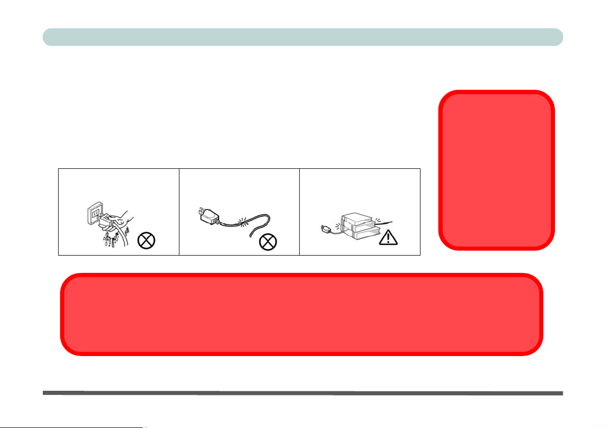
• When you want to unplug the power cord, be sure to disco nnect it by the plug head,
not by its wire.
• Make sure the socket and any extension cord(s) you use can support the total current
load of all the connected devices.
• Before cleaning the computer, make sure it is disconnected from any external power
supplies.
Do not plug in the power
cord if you are wet.
Do not use the power cord if
it is broken.
Do not place heavy objects
on the power cord.
Before you undertake
any upgrade procedures, make sure that
you have turned off the
power, and disconnected all peripherals
and cables (including
telephone lines).
Mainboard Battery Note
CAUTION: Danger of explosion if battery is incorrectly replaced. Replace only with the same or equivalent type
recommended by the manufacturer. Discard a used battery according to the manufacturer’s instructions.
Preface
Power Safety
Warning
V
Page 8

Preface
Cleaning
Do not apply cleaner directly to the computer, use a soft clean cloth.
Do not use volatile (petroleum distillates) or abrasive cleaners on any part of the computer.
Servicing
Do not attempt to service the computer yourself. Doing so may violate your warranty and expose you and the
computer to electric shock. Refer all servicing to authorized service personnel. Unplug the computer from the
power supply. Then refer servicing to qualified service personnel under any of the following conditions:
• When the power cord is damaged or frayed.
• If the computer has been exposed to any liquids.
• If the computer does not work normally when you follow the operating instructions.
• If the computer has been dropped or damaged (do not touch the poisonous liquid if the LCD panel breaks).
• If there is an unusual odor, heat or smoke coming from your computer.
VI
Page 9

Preface
Ergonomics
We designed your LCD PC system to be functional as well as attractive. To get most out of it, here are some
suggestions on how to position and use the computer:
• The top third of the LCD (screen) should be at eye-level or slightly below.
• The LCD should be at least 18"/45cm. directly in front of you.
• If the screen resolution (e.g. 1024x768) makes you strain to read, change it: In Windows Control Panel, double-click
Display (icon) and click Settings (tab). Then adjust the “Screen area” to something more comfortable (e.g.
800x600).
• Angle the LCD so that it doesn’t reflect any light into your eyes.
• Use a chair which offers good back support (e spec ial ly lower-back). The seat should allow your feet to rest flat on
the floor or on a footrest directly in front of you.
• If possible, illuminate your work area with natural daylig ht or use a steady-glowing (non-flickering) light source.
• Place the keyboard and mouse so that your arms are at your sides and your forearms are roughly parallel to the floor .
Your wrists should flex slightly downward as you work. Your neck and shoulders should also be relaxed.
• Take a break from the computer. Get up, stretch, flex your wrists, walk about, and look at something else for about
10 minutes every hour.
VII
Page 10

Preface
VIII
Page 11

Contents
Notice ..............................................................................I
FCC Statement ............................................................... .II
Instructions for Care and Operation ........................IV
Power Safety ............................................................. V
Cleaning ...................................................................VI
Servicing .................................................................. VI
Ergonomics ..................................................................VII
Quick Start Guide
Overview .....................................................................1-1
Advanced Users .........................................................1-2
Beginners and Not-So-Advanced Users ....................1-2
Warning Boxes ..........................................................1-2
Not Included ..............................................................1-3
System Software .................................................. ......1-3
System Startup .............................................................1-4
Model Types and Design Differences .........................1-5
System Map: Front View .............................................1-6
LED Indicators ..........................................................1-7
Power Button .............................................................1-7
Optical (CD/DVD) Device ..........................................1-8
Loading Discs ...........................................................1-8
Handling CDs or DVDs ...........................................1-8
DVD Regional Codes ................................................1-9
Preface
System Map: Left View .............................................1-10
System Map: Right View ...........................................1-11
System Map: Rear View ............................................1-12
Windows XP Start Menu & Control Panel ................1-13
Video Features ...........................................................1-14
Display Devices & Options ....................................1-14
Power Management Features .....................................1-16
Adding a Printer ................................................. .... ....1-17
USB Printer ..............................................................1-17
Install Instructions: .................................................1-17
Parallel Printer ........................................................ .1-17
Install Instructions: .................................................1-17
Advanced Controls
Overview ......................................................................2-1
Advanced Video Controls ............................................2-2
Dynamic Video Memory Technology ......................2-2
Intel Graphics Properties .............................................2-3
Scheme Options .........................................................2-5
Attaching Other Displays .............................................2-6
Display Modes .............................................................2-7
Audio Features ...........................................................2-11
7-in-1 Card Reader .....................................................2-12
PC Card Slot .................................................. ............2-13
IX
Page 12

Preface
Inserting and Removing PC Cards ..........................2-13
Power Management ...................................................2-14
Power Schemes ........................................................2-15
System Power Options ............................................2-16
Hibernate Mode vs. Shutdown ...............................2-16
Standby Mode vs. Hibernate Mode ........................ 2-16
Standby ...................................................................2-17
Hibernate ................................................................2-17
Configuring the Power Button ................................2-18
Intel PRO/Wireless WLAN Module .........................2-19
Intel WLAN Driver Installation .............................2-20
802.11b/g WLAN Module .........................................2-21
Wireless LAN (802.11b/g) Driver Installation ......2-21
Bluetooth Module ......................................................2-23
Bluetooth Driver Installation ..................................2-23
Touch Panel Module ..................................................2-25
Touch Panel Driver Installation .............................2-25
Calibrating the Touch Panel ...................................2-26
Drivers & Utilities
What to Install .............................................................3-1
Module Driver Installation ........................................3-1
Service Packs .............................................................3-3
Authorized Driver Message .......................................3-4
Version Conflict Message .........................................3-4
Updating/Reinstalling Individual Drivers .................3-4
Driver Installation ........................................................3-5
Service Pack Installation ..........................................3-6
New Hardware Found ................................................3-6
Manual Driver Installation .......................................3-6
Chipset ......................................................................3-7
Video ........................................................................3-7
Audio ........................................................................3-7
Modem ......................................................................3-8
LAN ..........................................................................3-8
PCMCIA/Card Reader ..............................................3-8
Wireless LAN ...........................................................3-9
Bluetooth ..................................................................3-9
Touch Panel ..............................................................3-9
BIOS Utilities
Overview ......................................................................4-1
The Power-On Self Test (POST) .................................4-2
Failing the POST .......................................................4-3
Fatal Errors ...............................................................4-3
Non-Fatal Errors .......................................................4-3
The Setup Program ......................................................4-4
Entering Setup ...........................................................4-4
Setup Screens .............................................................4-5
Main Menu ...................................................................4-6
X
Page 13

Preface
System Time & Date (Main Menu) .............................4-6
Legacy Diskette A: (Main Menu) ................................4-7
IDE Channel 0/1 Master (Main Menu) .......................4-7
System/Extended Memory (Main Menu) ....................4-7
Advanced Menu ...........................................................4-8
Chipset Information Menu (Advanced Menu) ............4-8
National 392 SIO Control Sub-Menu ..........................4-8
Reset Configuration Data: (Advanced Menu) .............4-9
Legacy USB Support: (Advanced Menu) ....................4-9
Boot-time Diagnostic Screen: (Advanced Menu) .......4-9
Power On Boot Beep: (Advanced Menu) ....................4-9
Total Graphics Memory: (Advanced Menu) ...............4-9
Security Menu ...........................................................4-10
Set Supervisor Password (Security Menu) ................4-10
Password on boot: (Security Menu) ..........................4-11
Fixed disk boot sector: (Security Menu) ...................4-11
Boot Menu .................................................................4-12
Exit Menu ..................................................................4-13
Upgrading The Computer
Overview .....................................................................5-1
When Not to Upgrade ................................................5-2
Upgrading the Hard Disk Drive ..................................5-3
Upgrading the System Memory (RAM) ......................5-5
Upgrading the Optical Device (Model A) ...................5-8
Upgrading the Optical Device (Model B) ..................5-10
Troubleshooting
Overview ......................................................................6-1
Basic Hints and Tips ....................................................6-2
Backup and General Maintenance ...............................6-3
Viruses .........................................................................6-4
Upgrading and Adding New Hardware/Software ........6-5
Problems & Possible Solutions ....................................6-7
Interface (Ports & Jacks)
External Monitor Port .................................................A-1
Headphone-Out Jack ...................................................A-1
Line-In Jack ................................................................A-1
Microphone-In Jack ....................................................A-1
IEEE 1394a Port .................................................... ... ..A-2
Printer/Parallel Port .....................................................A-2
RJ-11 Phone Jack ........................................................A-2
RJ-45 LAN Jack ..........................................................A-2
Security Lock Slot ......................................................A-2
Serial Port ...................................................................A-3
USB 2.0/1.1 Ports .......................................................A-3
XI
Page 14

Preface
Specifications
Processor Types ..........................................................B-2
Core Logic ..................................................................B-2
LCD ............................................................................ B-2
Memory ......................................................................B-3
Video Controller .........................................................B-3
BIOS ........................................................................... B-3
Storage ........................................................................ B-3
Audio .......................................................................... B-3
PC Card Sockets .........................................................B-3
Interface ...................................................................... B-4
Communication .......................................................... B-4
Power Management ....................................................B-4
Power .......................................................................... B-4
Environmental Spec ....................................................B-4
Dimensions & Weight ................................................B-4
Optional ...................................................................... B-5
XII
Page 15

Quick Start Guide
Chapter 1: Quick Start Guide
Overview
This Quick Start Guide is a brief introduction to the basic features of your computer, to navigating around the
computer and to getting your system started. The remainder of the manual covers the following:
• Chapter 2 A guide to the video, audio and power saving features of the computer, and to the computer’s 7-in-
1 Card Reader, Wireless LAN, Bluetooth and Touch Panel modules (some of which may be
optional depending on your purchase configuration).
• Chapter 3 The installation of the drivers and utilities essential to the operation or improvement of some of the
computer’s subsystems.
• Chapter 4 An outline of the computer’s built-in software, or BIOS (Basic Input Output System).
• Chapter 5 Instructions for upgrading your computer.
• Chapter 6 A troubleshooting guide.
• Appendix A Definitions of the interface, ports/jacks which allow your computer to communicate with external
devices.
• Appendix B The computer’s specification.
1
Overview 1 - 1
Page 16

1
Quick Start Guide
Advanced Users
If you are an advanced user you may skip over most of this Quick Start Guide. However you may find it useful
to refer to
“What to Install” on page 3 - 1, “BIOS Utilities” on page 4 - 1 and “Upgrading The Computer” on
page 5 - 1 in the User’s Manual. You may also find the notes marked with a of interest to you.
Beginners and Not-So-Advanced Users
Notes
Check the light colored
boxes with the mark
above to find detailed
information about the
computer’s features.
If you are new to computers (or do not have an advanced knowledge of them) then
the information contained in the Quick Start Guide should be enough to get you up
and running. Eventually you should try to look through all the documentation (more
detailed descriptions of the functions, setup and system controls are covered in the
remainder of the User’s Manual), but do not worry if you do not understand every
thing the first time. Keep this manual nearby and refer to it to learn as you go. You
may find it useful to refer to the notes marked with a
as indicated in the margin.
For a more detailed description of any of the interface ports and jacks see
(Ports & Jacks)” on page A - 1.
Warning Boxes
No matter what your level please pay careful attention to the warning and safety information indicated by the
symbol. Also please note the safety and handling instructions as indicated in the Preface.
-
“Interface
1 - 2 Overview
Page 17

Quick Start Guide
Not Included
Operating Systems (e.g. Windows XP etc.) and applications (e.g. word processing, spreadsheet and database programs) have their own manuals, so please consult the appropriate manuals.
System Software
Your computer may already come with system software pre-installed. Where this is not the case, or where you
are re-configuring your computer for a different system, you will find this manual refers to the following oper
ating systems:
• Microsoft Windows XP (Home & Professional Editions)
Drivers
If you are installing new system software, or are re-configuring your computer for a different system, you will need to install
the drivers listed in “Drivers & Utilities” on page 3 - 1. Drivers are programs which act as an interface between the computer and a hardware component e.g. a wireless network module. It is very important that you install the drivers in the order
listed in Table 3 - 1, on page 3 - 6. You will be unable to use most advanced controls until the necessary drivers and utilities are properly installed. If your system hasn’t been properly configured (your service representative may have already
done that for you), refer to “What to Install” on page 3 - 1 for installation instructions.
1
-
Overview 1 - 3
Page 18

1
Quick Start Guide
System Startup
1. Remove all packing materials, CDs/DVDs, floppy disks, and any PC Cards.
2. Securely attach any peripherals you want to use with the computer (e.g. keyboard and mouse) to their ports.
3. Attach the AC power cord to the AC-In jack on the right of the computer.
outlet.
4. Push the power button to turn the computer “on”.
Shutdown
Please note that you should always shut your computer down by choosing the Shut Down/Turn Off Computer command
from the Start menu in Windows. This will help prevent hard disk or system problems.
Then plug the AC power cord into an
1 - 4 System Startup
Page 19
Quick Start Guide
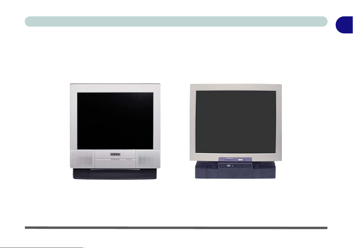
Model Types and Design Differences
There two model types (pictured below) in this LCD PC series. The model types differ in physical appearance
(Model A’s optical CD/DVD device bay is located on the left side of the computer; Model B’s is at the front)
and their specifications.
1
Model A
Figure 1 - 1 - Model Types & Design Differences
Model Types and Design Differences 1 - 5
Model B
Page 20
1
Quick Start Guide
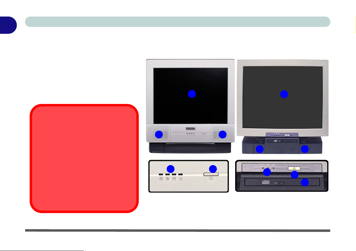
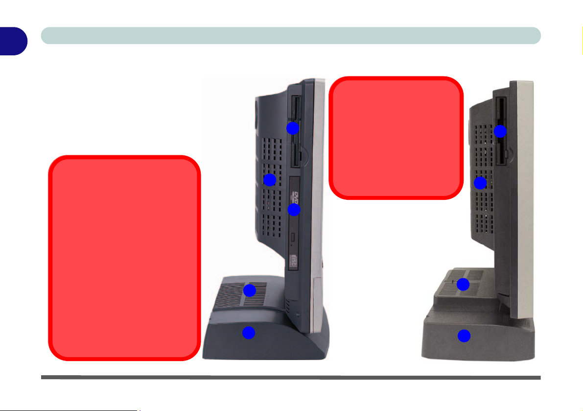
System Map: Front View
1. LCD Panel
2. Speakers
3. LED Indicators
4. Power Button
5. Optical (CD/DVD) Device Bay (Model B
Only - see page 1 - 10 for Model A)
6. Keyboard Holder (Model B Only)
CD/DVD Emergency Eject
Model A
1
Model B
1
If you need to manually eject a CD/DVD (e.g.
due to an unexpected power interruption) you
may push the end of a straightened paper clip
into the emergency eject hole. Do not use a
sharpened pencil or similar object that may
break and become lodged in the hole.
Media Warning
Don’t try to remove a floppy disk/CD/DVD
while the system is accessing it. This may
cause the system to “crash”.
1 - 6 System Map: Front View
2
3
Figure 1 - 2 - Front View
2
6 6
4
3
4
5
Page 21
Quick Start Guide
1
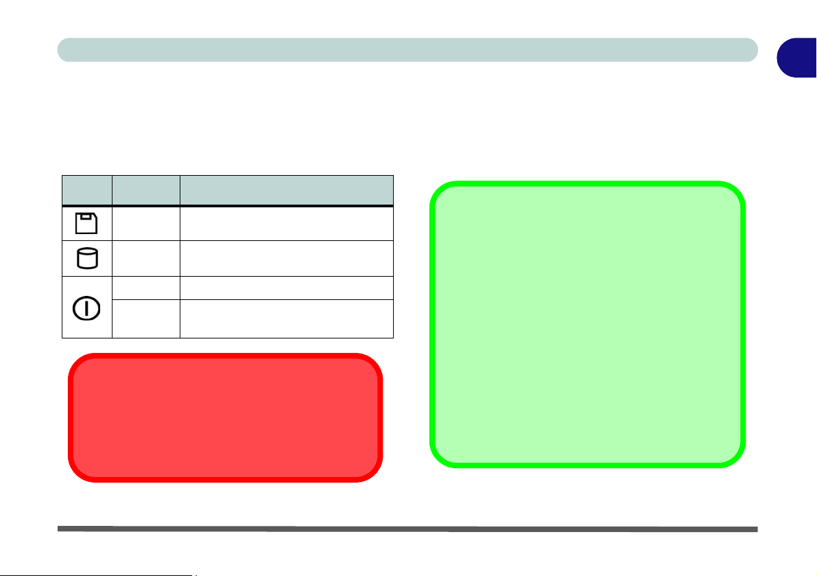
LED Indicators
The LED indicators on the computer display helpful
information about the current status of the computer.
Table 1 - 1 - LED Indicators & Power Button
Icon Color Description
Green Floppy Disk Drive Activity
Green Hard Disk Drive Activity
Green System Power is On
Flashing
Orange
System is in Standby Mode
System Shutdown Warning
After shutting the computer down, allow time for the
system to shut down properly (i.e. the fan stops turning) before attempting to turn the system on again.
Power Button
When the computer is on, you can use the power button as a hot-key button when it is pressed for less than
4 seconds. Use Power Options in the “Windows” con
trol panel to configure this feature.
Forced Off
If the system “hangs”, and the Ctrl + Alt + Del key
combination doesn’t work, press the power button for
4 seconds to force the system to turn itself off.
Power Button as Standby or Hibernate
Button
If you are using an ACPI-compliant OS, such as Windows XP, the power button can be designated as
Standby or Hibernate button within the OS’s “P ower
Options” subsystem (see your OS’s documentation,
“Configuring the Power Button” on page 2 - 18
or
for details).
-
System Map: Front View 1 - 7
Page 22

1
Quick Start Guide
Optical (CD/DVD) Device
There is a bay for a 5.25" optical (CD/DVD) device
(12.7mm height)
model you purchased (see
The optical device is usually labeled “Drive D:” and
may be used as a boot device if properly set in the
BIOS (see
Loading Discs
To insert a CD/DVD, press the open button and
carefully place a CD/DVD onto the disc tray with label-side facing up (use just enough force for the disc to
click onto the tray’s spindle). Gently push the CD/
DVD tray in until its lock “clicks” and you are ready
to start. The busy indicator
is being accessed, or while an audio/video CD, or
DVD, is playing. If power is unexpectedly interrupted,
insert an object such as a straightened paper clip into
the emergency eject hole
. The actual device will depend on the
“Storage” on page B - 3).
“Boot Menu” on page 4 - 12).
will light up while data
2
to open the tray.
3
1
2
3
1
Handling CDs or DVDs
Proper handling of your CDs/DVDs will prevent them
from being damaged. Please follow the advice below
to make sure that the data stored on your CDs/DVDs
can be accessed.
Note the following:
• Hold the CD or DVD by the edges; do not touch
the surface of the disc.
• Use a clean, soft, dry cloth to remove dust or fingerprints.
• Do not write on the surface with a pen.
• Do not attach paper or other materials to the surface of the disc.
• Do not store or place the CD or DVD in high-temperature areas.
• Do not use benzene, thinner, or other cleaners to
clean the CD or DVD.
• Do not bend the CD or DVD.
• Do not drop or subject the CD or DVD to shock.
Figure 1 - 3 - Optical (CD/DVD Device)
1 - 8 Optical (CD/DVD) Device
Page 23
Quick Start Guide
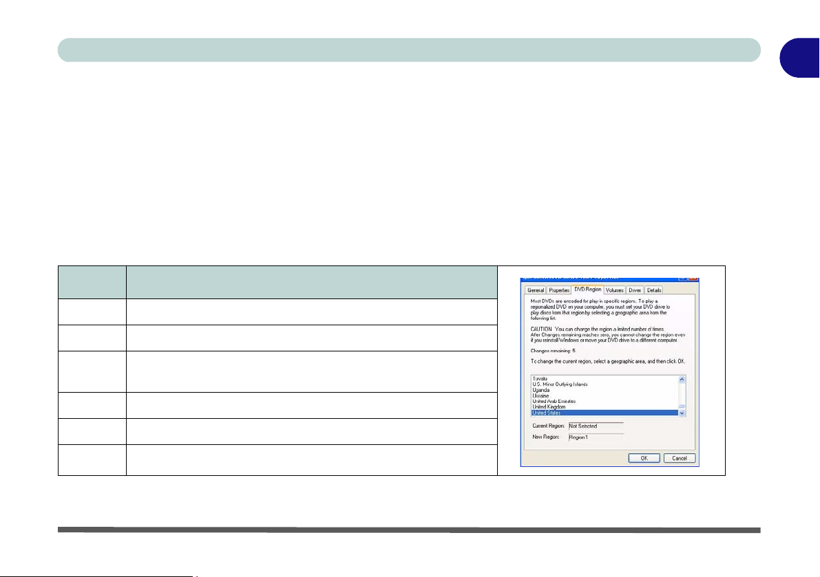
DVD Regional Codes
DVD region detection is device dependent, not OS-dependent. You can select your module’s region code 5
times. The fifth selection is permanent. This cannot be altered even if you change your operating system or you
use the module in another computer.
Changing DVD Regional Codes
1. Go to the Control Panel and double-click System > Hardware (tab).
2. Click Device Manager, then click the + next to DVD/CD-ROM drives.
3. Double-click on the DVD-ROM d evice to bring up the Properties box, and select the DVD Region (tab) to br ing
up the control panel to allow you to adjust the regional code
Region Geographical Location
1 USA, Canada
2 Western Europe, Japan, South Africa, Middle East & Egypt
.
1
3
4 South & Central America, Mexico, Australia, New Zealand
5 N Korea, Russia, Eastern Europe, India & Most of Africa
6China
South-East Asia, Taiwan, South Korea, The Philippines,
Indonesia, Hong Kong
Table 1 - 2 - DVD Regional Coding
Optical (CD/DVD) Device 1 - 9
Page 24
1
Quick Start Guide
System Map: Left View
Figure 1 - 4 - Left View
1. Floppy Disk Drive Module
2. Vent
3. Hard Disk Drive Bay
4. Optical (CD/DVD) Device Bay
(Model A Only)
CD/DVD Emergency Eject
Overheating
1
2
To prevent your computer
from overheating make sure
nothing blocks the vent/fan
intake while the computer is
in use.
1
2
If you need to manually eject a CD/
DVD (e.g. due to an unexpected
power interruption) you may push
the end of a straightened paper clip
into the emergency eject hole. Do
not use a sharpened pencil or similar
object that may break and become
lodged in the hole.
Media Warning
Don’t try to remove a floppy disk/CD/
DVD while the system is accessing
it. This may cause the system to
“crash”.
1 - 10 System Map: Left View
4
2
2
Model A Model B
3
3
Page 25
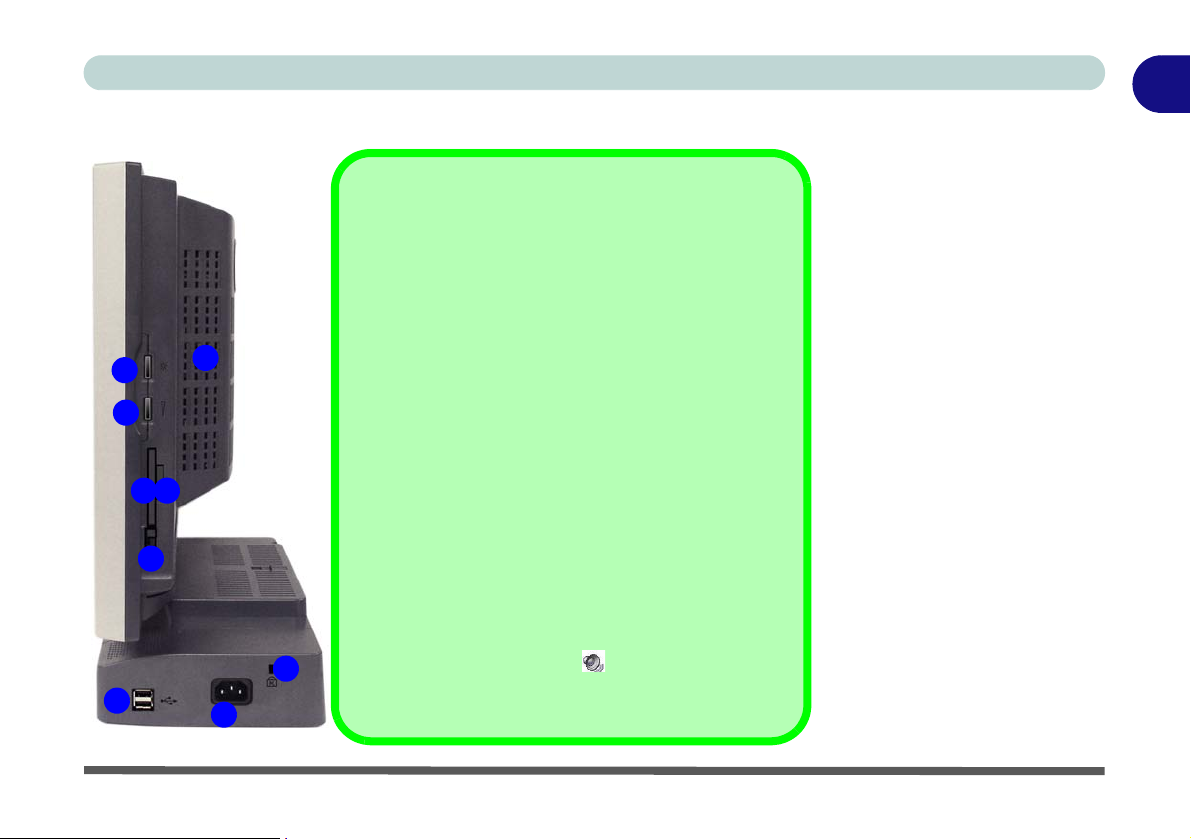
System Map: Right View
7-in-1 Card Reader Formats
The card reader allows you to use the most popular
digital storage card formats (see page 2 - 12):
• MMC (MultiMedia Card)
• SD (Secure Digital)
1
9
2
4
3
The computer is equipped with a PCMCIA 3.3V/5V
slot (see page 2 - 13).
5
How high the sound volume can be set depends on
the setting of the volume control within Windows, and
the volume control knob on the right of the com-
8
6
7
puter. Click the volume icon in the taskbar to check
the setting (see “Audio Features” on page 2 - 11).
• MS (Memory Stick)
• MS Pro (Memory Stick Pro)
• MS Duo (requires PC adapter)
• Mini SD (requires PC adapter)
• RS MCC (requires PC adapter)
Sound Volume Adjustment
The PC Card Slot
Quick Start Guide
Figure 1 - 5 - Right View
1. LCD Brightness Control
Knob
2. Volume Control Knob
3. 7-in-1 Card Reader
4. PC Card Slot
5. PC Card Eject Button
6. 2 * USB 2.0 Ports
7. AC-In Jack
8. Security Lock Slot
9. Vent
Note: Only Model B is pictured
(right and rear views), however the
port locations etc. are identical to
Model A.
1
System Map: Right View 1 - 11
Page 26
1
Quick Start Guide
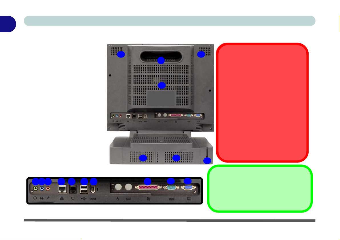
System Map: Rear View
Figure 1 - 6 - Rear View
1. Carrying Handle
2. Headphone-Out Jack
3. Line-In Jack
4. Microphone-In Jack
5. RJ-45 LAN Jack
6. RJ-11 Phone Jack
7. 2 * USB 2.0 Ports
8. Unpowered - IEEE 1394
Port
9. Printer/Parallel Port
10. Serial Port
11. External Monitor Port
12. Vents
13. Hard Disk Bay Screw
32 54 6 7 8 9
12 12
1
12
12 12
10 11
Handle Warning
We strongly recommend using both
hands to move the computer (one
hand gripping the handle and the
other gripping the base) to avoid
accidentally dropping it.
Port Warning
The computer can only accept one
keyboard at a time. Don’t try to install more than one keyboard at the
same time. Doing so may cause resource conflicts and make the system unstable.
13
IEEE 1394
1 - 12 System Map: Rear View
The IEEE 1394 port only supports SELF
POWERED IEEE 1394 devices.
Page 27
Quick Start Guide
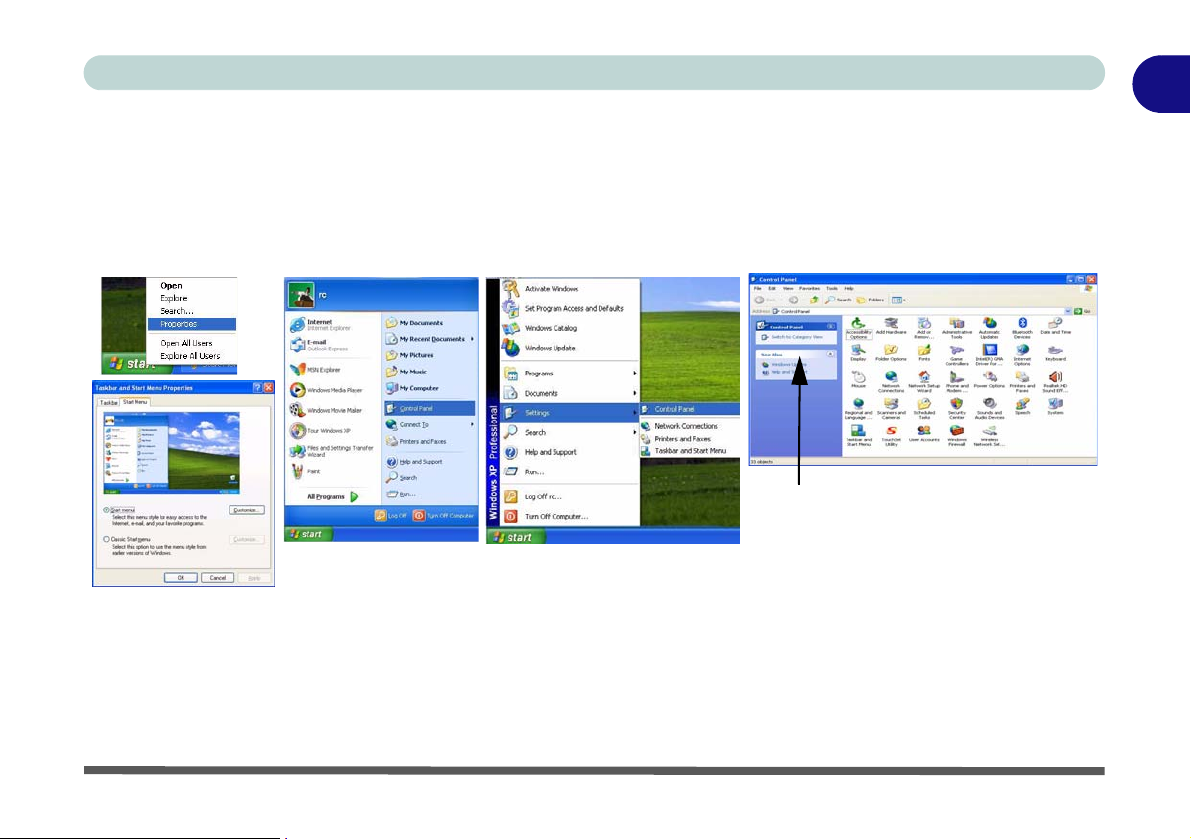
Windows XP Start Menu & Control Panel
Most of the control panels, utilities and programs within Windows XP (and most other Windows versions) are
accessed from the Start menu. When you install programs and utilities they will be installed on your hard disk
drive, and a shortcut will usually be placed in the Start menu and/or the desktop. To customize the look of the
Start menu, right-click Start, and select Properties from the menu.
Click here to toggle Category View
Figure 1 - 7 - Start Menu & Control Panel
In many instances throughout this manual you will see an instruction to open the Control Panel. The Control
Panel is accessed from the Start menu, and it allows you to configure the settings for most of the key features
in Windows (e.g. power, video, network, audio etc.). Windows XP provides basic controls for many of the fea
tures, however many new controls are added (or existing ones are enhanced) when you install the drivers listed
in
Table 3 - 1, on page 3 - 6. To see all controls it may be necessary to toggle off Category View.
1
-
Windows XP Start Menu & Control Panel 1 - 13
Page 28

1
Quick Start Guide
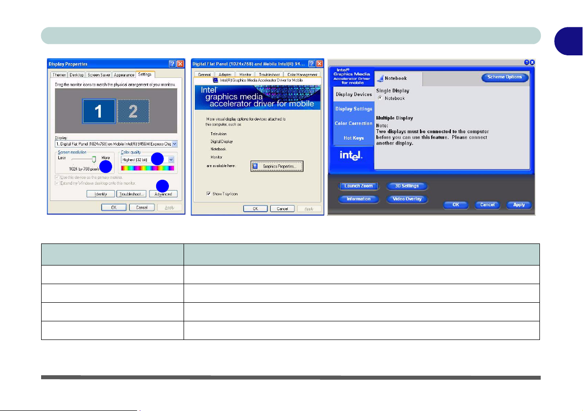
Video Features
Your computer has built-in Intel on-board video. You can switch display devices, and configure display options,
from the Display Properties control panel in Windows as long as the appropriate video driver is installed (see
“Advanced Video Controls” on page 2 - 2).
To access Display Properties in Windows:
1. Click Start, point to Settings and click Control Panel (or just click Control Panel).
2. Double-click Display (icon) - In the Appearances and Themes category.
3. Click Settings (tab) in the Display Properties dialog box.
4. Move the slider to the preferred setting in Screen resolution (Figure 1 - 8 on page 1 - 15).
5. Click the arrow, and scroll to the preferred setting in Color quality (Figure 1 - 8 on page 1 - 15).
6. Click Advanced (button) (Figure 1 - 8 on page 1 - 15) to bring up the Advanced properties tabs.
7. Click Inte l(R) Gra phics Media Ac celerat or Driver for Mobi le (t ab) , and click Graphics Propert ies (b utton) to
make any video adjustments you require.
8. You can also access Display Properties by right-clicking the desktop and scrolling down and clicking
Properties. Click Settings (tab) and adjust as above.
9. You can also access Intel(R) GMA Driver for Mobile from the taskbar icon menu.
3
Display Devices & Options
Besides the built-in LCD, you can also use an external VGA monitor (CRT) or external Flat Panel Display
connected to the external monitor port as your display device.
1
2
1 - 14 Video Features
Page 29
Quick Start Guide
1
1
2
3
Figure 1 - 8 - Display Properties Desktop
Intel Display Mode Description
Single Mode One of the connected displays is used as the display device
Twin Mode
Intel(R) Dual Display Clone Mode Both connected displays output the same view and may be configured independently
Extended Desktop Mode Both connected displays are treated as separate devices, and act as a virtual desktop
This mode will drive multiple displays with the same content and resolutions, color quality etc.
Table 1 - 3 - Display Options
Video Features 1 - 15
Page 30
1
Quick Start Guide
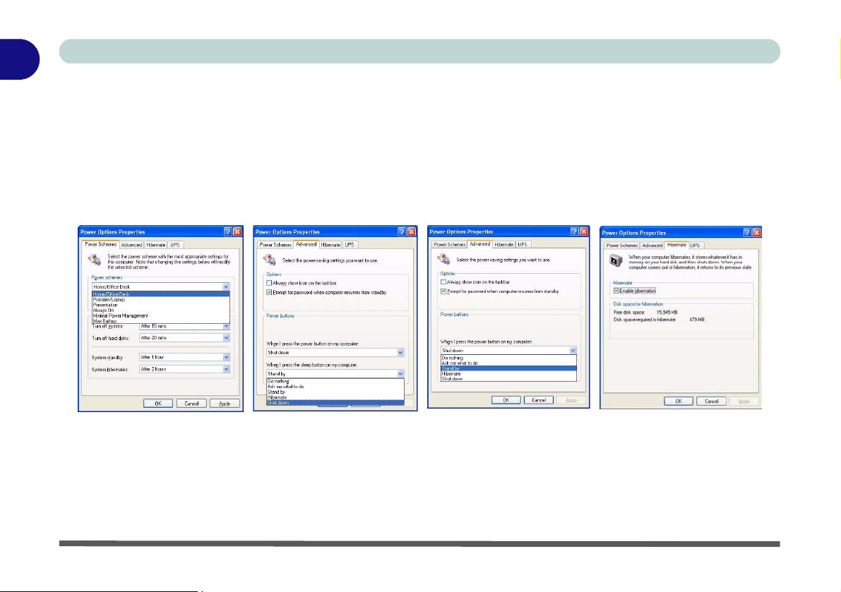
Power Management Features
The Power Options control panel in Windows (see page 1 - 13) allows you to configure power management features for your computer. You may conserve power through individual components such as the monitor or hard
disk (by means of Power Schemes), or you may use either Standby or Hibernate mode to conserve power
throughout the system (enable Hibernate support from the control panel as pictured in
some form of power management greatly increases the life span of the LCD.
Figure 1 - 9 - Power Options
Figure 1 - 9). Using
1 - 16 Power Management Features
Page 31

Quick Start Guide
Adding a Printer
The most commonly used peripheral is a printer. The following conv entions will help you to add a pr inter, how ever it is always best to refer to the printer manual for specific instructions and configuration options.
USB Printer
Most new printers have a USB interface connection. You may use any one of the ports to connect the printer.
Install Instructions:
1. Set up the printer according to its instructions (unpacking, paper tray, toner/ink cartrid ge etc.).
2. Turn ON the computer.
3. Turn ON the printer.
4. Connect the printer’s USB cable to one of the USB ports on the computer.
5. Windows will identify the printer and either load one of its own drivers or ask you to supply one. Follow the onscreen instructions.
Parallel Printer
This is still a very common type of printer.
Install Instructions:
1. Set up the printer according to its instructions (unpacking, paper tray, toner/ink cartrid ge etc.).
2. Connect the printer’s parallel cable to the Parallel port.
3. Turn ON the printer, then the computer.
4. Windows will identify the printer and either load one of its own drivers or ask you to supply one. Follow the onscreen instructions.
1
Adding a Printer 1 - 17
Page 32

1
Quick Start Guide
1 - 18
Page 33

Advanced Controls
Chapter 2: Advanced Controls
Overview
This chapter covers:
• Advanced Video Controls
• Audio Features
• 7-in-1 Card Reader
• PC Card Slot
• Power Management
• Intel PRO/Wireless WLAN Module
• 802.11b/g WLAN Module
• Bluetooth Module
• Touch Panel Module
Drivers
You are unable to use
most advanced controls until the necessary drivers and
utilities are properly installed. If your system
hasn’t been properly
configured (your service representative
may have already
done that for you), refer to “What to In-
stall” on page 3 - 1 for
installation instructions.
2
Overview 2 - 1
Page 34

Advanced Controls
2
Advanced Video Controls
This section is about making adjustments for the LCD display, and switching display
DVMT Notes
The default memory
setting is 128MB, and
this may be adjusted to
either 64MB or
224MB. See “Total
Graphics Memory:
(Advanced Menu)”
on page 4 - 9.
DVMT is not local video memory.
DVMT will not function
in MS-DOS. DOS uses
the legacy memory indicated.
Figure 2 - 1
DVMT Memory
Requirements
devices. The basic settings for configuring the display are outlined in
“Video Fea-
tures” on page 1 - 14.
Dynamic Video Memory Technology
Intel® DVMT automatically and dynamically allocates as much (up to 224MB) system memory (RAM) as needed to the video system (the video driver must be in-
stalled - see page 3 - 1). DVMT returns whatever memory is no longer needed to
the operating system.
Information Tab
The information ta b in Graphics
Properties in the intel(R) Graphics Media Accelerator Driver
(tab) lists details of your computer’s memory etc. See “Intel
Graphics Properties” on page 2
- 3 to see how to access this Infor-
mation tab.
2 - 2 Advanced Video Controls
Page 35

Advanced Controls
Intel Graphics Properties
More advanced video configuration options are provided by the Intel(R) Graphics
Media Accelerator Driver for Mobile.
1. Open Display Properties (see “Video Features” on page 1 - 14) and click
Advanced.
2. Click the Intel(R)... tab and click Graphics Properties (button).
3. You can also access Graphics Properties from the Windows Intel(R) GMA
Driver for Mobile control panel, or from the taskbar icon menu.
Taskbar Icon
You can also access the
controller properties
from the taskbar. Click
on the icon to bring up
the menu and scroll to
Graphics Properties.
If you cannot see the
tray icon go to the In-
tel(R) Graphics Media
Accelerator Driver tab
(in the Display Properties > Advanced op-
tions) and click the
“Show Tray Icon” tickbox.
Figure 2 - 2
Intel Graphics
Properties
2
Intel Graphics Properties 2 - 3
Page 36

Advanced Controls
You may make changes to the devices, color, schemes, Hot Keys etc. by clicking
2
Right-click on many of
the items in the tabs to
bring up the “What’s
This?” button.
Click the “What’s This?”
button to bring up the
help menu.
Multiple Display
At least one other display must be attached in
order to view Multiple
Display options.
Help Menus
the appropriate menu item or button. Click Information (button) to obtain useful information about the graphics properties of the computer, and see the Support tab in
Information to get weblinks to the latest information on the Intel Website.
Figure 2 - 3
Intel Graphics Media
Accelerator Driver
for mobile
(Control Panel Tabs)
2 - 4 Intel Graphics Properties
Page 37

Advanced Controls
Scheme Options
Use Scheme Options to configure quick settings for applications which require specific resolution and color settings in order to run properly e.g. games, multimedia
programs. To set the scheme options:
1. Open the Intel(R) GMA Driver for Mobile control panel (see “Intel Graphics
Properties” on page 2 - 3).
2. Configure your display configura tion, re solution etc. a s per your r equire men ts from
Display Settings.
3. Click on Scheme Options (button).
4. Type a name for the scheme.
5. If you want to automatically launch an application when running the scheme click
on Browse (button).
6. Browse to the executable file for the application you want to set the scheme for
(see sidebar), and click Open to select it.
7. Click Save to save the settings (you can click in the "Restore the display
settings after exiting this application" box to return to your original settings
when you exit the program).
8. Click OK to exit Scheme Options.
9. Click the taskbar icon and scroll to Select Scheme to choose the scheme to
run.
Application.exe
You will need to locate
the actual application
executable (.exe) file,
not just the shortcut. To
find the application rightclick its shortcut on the
desktop click Proper-
ties. Click the Shortcut
(tab) and see where the
executable file is located
by clicking the Find Tar-
get (button). Note the location and you will then
be able to browse to this
file.
Figure 2 - 4
Select Scheme
2
Intel Graphics Properties 2 - 5
Page 38

Advanced Controls
2
Intel Display Note
Note that the notebook
(i.e. the built-in LCD) is
the default Primary display device and may not
be changed.
Attaching Other Displays
Besides the built-in LCD, you can also use an external monitor/flat panel display as
a display device. The following are the display options:
1. The built-in LCD OR an external monitor/flat panel display connected to the external monitor port (Single Display).
2. The built-in LCD AND an external monitor/flat panel display connected to the
external monitor port (Multiple Display).
If you want to use an external display, follow these instructions.
1. Attach your external monitor to the external monitor port, and turn it on.
2. Go to the Intel (R) GMA Driver for Mobile control panel (see “Intel Graphics
Properties” on page 2 - 3).
3. Click to choose the display option from the Multiple or Single Display menu.
4. Click Apply (and OK to confirm the settings change) and OK (button).
Figure 2 - 5
Display Devices
2 - 6 Attaching Other Displays
Page 39

Advanced Controls
Display Modes
Single Display
Only one of your attached displays is used.
Twin
This mode will drive multiple displays with the same content and resolutions, color
quality etc. See
Extended Desktop
This mode allows a desktop to span multiple displays and acts as a large workspace.
This creates a lot more screen area for display. Use the Display Properties (tab) to
drag the monitors to match the physical arrangement you wish to use, or you may
also use the Windows Display Properties (control panel) to configure the relative
size and position.
Intel(R) Dual Display Clone
This mode will drive multiple displays with the same content. Each device may be
configured independently for different resolutions, refresh rates, color quality etc.
Use this feature to display the screen through a projector for a presentation.
“Twin Mode Support” on page 2 - 8 for more information.
2
Display Modes 2 - 7
Page 40

Advanced Controls
To Enable Intel(R) Dual Display Clone Mode
2
Twin Mode Support
The Twin mode option
will only appear if the
LCD PC (notebook) and
external monitor support
the same resolution
(e.g. 1280 * 800). Check
any documentation supplied with an external
monitor to see supported resolutions.
1. Attach your external monitor to the external monitor port, and turn it on.
2. Go to the Intel (R) GMA Driver for Mobile control panel (see “Intel Graphics
Properties” on page 2 - 3).
3. Click to choose Intel(R) Dual Display Clone or Twin from Display Device (tab).
4. Click Apply, and OK to confirm the settings change.
5. Click Display Settings to adjust the settings for the attached devices.
Clone Mode
Figure 2 - 6
Display Devices &
Settings
Twin Mode
2 - 8 Display Modes
Page 41

To Enable Extended Desktop Mode:
1. Attach your external monitor to the external monitor port, and turn it on.
2. Go to the Intel (R) GMA Driver for Mobile control panel (see “Intel Graphics
Properties” on page 2 - 3).
3. Click to choose Extended Desktop from Display Device (tab).
4. Click Apply, and OK to confirm the settings change.
5. Click Display Settings to adjust the settings for the attached devices.
Click the appropriate monitor
icon and drag it to match the
physical arrangement you
wish to use (e.g. the secondary display may be extended
left/right/above/below the
primary display).
Click Display Settings to
make any adjustments required.
Advanced Controls
Display Settings
Extended Desktop
You can have different
Colors, Screen Area
and Monitor Refresh
Rates for each display
device provided your
monitor can support
them.
You can drag the monitor icons to match the
physical layout of your
displays. Icons and programs may also be
dragged between the
displays.
2
You can also enable the Extended Desktop mode from the Display Properties control panel (see page 2 - 10).
Figure 2 - 7
Extended Desktop
Mode
Display Modes 2 - 9
Page 42

Advanced Controls
To Enable Extended Desktop (Display Properties)
2
Display Settings
Extended Desktop
Use the control panel to
drag the monitors to
match the physical arrangement you wish to
use.
You can drag any icons
or windows across to either display desktop,
which makes it possible
to have one program
visible in one of the displays, and a different
program visible in the
other display.
1. Attach your external monitor to the external monitor port, and turn it on.
2. Click Start, point t o Settings (or click Control Panel) and click Control Panel (if
you are in Category View choo se Appearance and Themes).
3. Double-click Display (icon).
4. In the Display Properties dialog box, click Settings (tab).
5. Click the monitor icon (e.g. ), and make sure you have checked “Extend my
Windows desktop onto this monitor.” and click Apply.
2
Click the appropriate monitor
icon (e.g. ) to be able to select
2
the option to extend the desktop
on to it.
In this example the Primary mon-
1
itor is on the left, the secondary
display is on the right.
2
Figure 2 - 8
Display Properties
(Extended Desktop)
2 - 10 Display Modes
Page 43

Advanced Controls
Audio Features
You can configure the audio options on your computer from the Sounds and Audio
Devices
Realtek HD Audio Manager icon in the taskbar/control panel (this will bring up
the Realtek Audio Configuration menus).
Windows control panel (see Figure 1 - 7 on page 1 - 13), or from the
Sound Volume
Adjustment
How high the sound
volume can be set depends on the setting of
the volume control
within Windows (and
the volume control
knob on the computer). Click the Volume
icon on the taskbar to
check the setting.
Figure 2 - 9
Realtek Audio
Control Panel
2
Audio Features 2 - 11
Page 44

Advanced Controls
2
Card Reader Cover
Make sure you keep the
rubber cover provided in
the card reader when
not in use. This will help
prevent foreign objects
and/or dust getting in to
the card reader.
7-in-1 Card Reader
The card reader allows you to use some of the latest digital storage cards. Push the
card into the slot and it will appear as a removable device, and can be accessed in
the same way as your hard disk (s). Make sure you install the Card Reader driver
(see
“PCMCIA/Card Reader” on page 3 - 8).
• MMC (MultiMedia Card)
• SD (Secure Digital)
• MS (Memory Stick)
• MS Pro (Memory Stick Pro)
• MS Duo (requires PC adapter*)
• Mini SD (requires PC adapter*)
Figure 2 - 10
Right View
1. Card Reader
1
• RS MMC (requires PC adapter*)
*Note: The PC adapters are usually supplied with these
cards.
2 - 12 7-in-1 Card Reader
Page 45

Advanced Controls
PC Card Slot
The computer is equipped with a PCMCIA 3.3V/5V slot for one type II PCMCIA
CardBus PC Card Slot. Make sure you install the PCMCIA/Card Reader driver (see
see
“PCMCIA/Card Reader” on page 3 - 8).
Inserting and Removing PC Cards
• Align the PC Card with the slot and push it in until it
locks into place.
• To remove a PC Card, simply press the eject button
1
next to the slot.
1
PC Card Slot Cover
Make sure you keep the
cover in the PC Card
slot when not is use.
This will help prevent
foreign objects and/or
dust getting in to the PC
Card Slot.
Figure 2 - 11
Right View
1. PC Card Eject
Button
2
PC Card Slot 2 - 13
Page 46

Advanced Controls
2
Note that you should
always shut your computer down by choosing the Shut Down/
Turn Off Computer
command from the
Start menu in Windows. This will help
prevent hard disk or
system problems.
Shutdown
Power Management
The computer uses the ACPI power management system to conserve power by controlling individual components of the computer (the monitor and hard disk drive) or
the whole system.
Using some form of power management greatly increases the life span of the
LCD.
When the computer is on, you can use the power button as a Standby/Hibernate/
Shutdown hot-key button when it is pressed for less than 4 seconds (pressing and
holding the power button for longer than this will shut the computer down). Use
Power Options in the Windows control panel to configure this feature.
Forced Off
If the system “hangs”,
and the Ctrl + Alt + Del
key combination
doesn’t work, press the
power button for 4 sec-
onds, or longer, to
force the system to
turn itself off.
2 - 14 Power Management
Page 47

Advanced Controls
Power Schemes
You can set your computer to conserve power through individual components by
means of Power Schemes. You can also adjust the settings for each scheme to set
the monitor to turn off after a specified time, and the computer's hard disk motor to
turn off if the hard disk drive has not been accessed for a specified period of time (if
the system reads or writes data, the hard disk motor will be turned back on). The
schemes may also be set to set a specified time for the system to enter Standby or
Hibernate modes (see
“System Power Options” on page 2 - 16).
Resuming
Operation
The system can resume from Monitor or
Hard Disk Standby by
pressing a key on your
keyboard.
Figure 2 - 12
Power Schemes
2
Choose the Home/Office Desk scheme for maximum performance.
Power Management 2 - 15
Page 48

Advanced Controls
2
Power Button as
Hibernate Button
Fully ACPI-compliant
operating systems,
(such as Windows
XP) allow you to use
the OS’s “Power Options” control panel to
set the power button to
send the system into
Standby or Hibernate
mode (see your OS’s
documentation, or
“Configuring the
Power Button” on
page 2 - 18 for de-
tails).
Standby or
You can use the system power options to stop the computer’s operation and restart
where you left off. This system features Standby and Hibernate sleep mode levels
(Hibernate mode will need to be enabled by clicking the option in the Hibernate
tab in the Power Options control panel -
Figure 2 - 13 on page 2 - 17).
Hibernate Mode vs. Shutdown
Hibernate mode and Shutdown are the same in that the system is off and you need
to press the power button to turn it on. Their main difference is:
When you come back from hibernation, you can return to where you last left off
(what was on your desktop) without reopening the application(s) and file(s) you last
used.
You can use either method depending on your needs.
Standby Mode vs. Hibernate Mode
If you want to stay away from your work for just a while, you can put the system on
standby instead of in hibernation. It takes a longer time to wake up the system from
Hibernate mode than from Standby mode.
System Power Options
2 - 16 Power Management
Page 49

Advanced Controls
Standby
Standby saves the least amount of power, but takes the shortest time to return to full
operation. During Standby the hard disk is turned off, and the CPU is made to idle
at its slowest speed. All open applications are retained in memory. When you are not
using your computer for a certain length of time, which you specify in the operating
system, it will enter Standby mode to save power.
Hibernate
Hibernate uses no power and saves all of your information on a part of the HDD before it turns the system off. Although it saves the most power it takes the longest time
to return to full operation. You will need to enable Hibernate mode from the Hiber
nate tab in the Power Options control panel. The system will resume from Hibernate mode by pressing the power button.
System Resume
The system can resume
from Standby mode by:
• Pressing the power
button
• An alarm resume that
is enabled and expires
• An incoming call
-
received on the
modem (if enabled)
• Network card activity
(if enabled)
Figure 2 - 13
Enable Hibernation
2
Power Management 2 - 17
Page 50

Advanced Controls
2
Figure 2 - 14
Power Options
(Advanced - Power
Buttons)
The power button may be set to send the computer in to either Standby or Hibernate mode (Figure 2 - 14). In Standby mode, the Power LED will flash orange. In
Hibernate mode the Power LED will be off.
(Sleep) ButtonPower Button Sleep/Resume
(if your keyboard supports this function)
Configuring the Power Button
2 - 18 Power Management
Page 51

Advanced Controls
Intel PRO/Wireless WLAN Module
If you have included an Intel PRO/Wireless 3945ABG (802.11a/b/g) PCIe
WLAN module in your purchase option, make sure you install the drivers in the
order indicated in
To get help on the network settings you can view the User Guide from the Intel
PROSet / Wireless menu.
Table 3 - 1, on page 3 - 6.
2
Figure 2 - 15
Installation Screen
Intel PRO/Wireless WLAN Module 2 - 19
Page 52

Advanced Controls
2
User Guide
1. Insert the Device Drivers & Utilities + User’s Manual CD-ROM into the
CD/DVD drive.
2. Click Optional > Yes.
Intel WLAN Driver Installation
You can view the User
Guides from the
Drivers & Utilities + User’s Manual CD-ROM
Device
.
3. Click 1.Install Wireless Lan Driver > Yes.
OR
Navigate (Browse..) to D:\Others\WLAN\Intel\Autorun.exe and click
OK.
Click
Optional
and then click the
button. Click
Lan
>
Yes
View User Guide
Click
(button) as per
15 on page 2 - 19
(button)
1.Wireless
.
Figure 2 -
Unlock
.
4. Click Install Software (button).
5. Click the button to accept the license and click Next > Next > OK.
6. Click OK to complete the installation.
7.You can configure the settings by going to
the Intel (R) PROSet Wireless control
panel (Start > Programs/All Programs >
Intel PROSet Wireless), or by doubleclicking the taskbar icon .
Figure 2 - 16
Intel PROSet/
Wireless
2 - 20 Intel PRO/Wireless WLAN Module
Page 53

Advanced Controls
802.11b/g WLAN Module
If your purchase option includes the 802.11b/g Wireless LAN module, follow the
procedure below for driver installation instructions. You can then configure the op
tions from the Wireless Configuration Utility by clicking the icon in the Windows
control panel, or in the taskbar.
Wireless LAN (802.11b/g) Driver Installation
1. Insert the Device Drivers & Utilities + User’s Manual CD-ROM into the
CD/DVD drive.
2. Click Optional > Yes.
3. Click 1.Install Wireless Lan Driver > Yes.
OR
Navigate (Browse..) to D:\Others\WLAN\AW\Setup.exe and click OK.
4. Choose the language you prefer, and click OK.
5. Click Next (click Continue Anyway if a warning appears).
6. Click Finish to complete the installation.
7. The operating system is the default setting for Wireless LAN control in
Windows XP (see overleaf).
8. Access any available wireless networks from Network Connections >
Wireless Network Connection menu in Windows (see sidebar overleaf), or
click the icon in the taskbar, and click View Wireless Connections.
2
-
802.11b/g WLAN Module 2 - 21
Page 54

Advanced Controls
2
Use the
work Connections
trol panel to access
available wireless networks (
Network Connections
or
Start > Connect To >
Show all Connections
Network
Connection
Windows Net-
con-
Start > Se tting s >
).
Figure 2 - 17
Wireless Network
Control Panels
2 - 22 802.11b/g WLAN Module
Page 55

Advanced Controls
Bluetooth Module
If your purchase option includes the Bluetooth module, follow the procedure below
for driver installation instructions.
Bluetooth Driver Installation
1. Insert the Device Drivers & Utilities + User’s Manual CD-ROM into the
CD/DVD drive.
2. Click Optional > Yes.
3. Click 2.Install Bluetooth Driver > Yes.
OR
Click Start (menu) > Run... and navigate (Browse...) to
D:\Others\Bluetooth\SETUP.exe and click OK.
4. Click Install Drivers and Application v2.12.
5. Choose the language you prefer, and click OK.
6. Click Next.
7. Click the button to accept the license agreement, and then click Next.
8. Click Next > Next > Install.
9. Click Finish > Yes to restart the computer.
10. The IVT Corporation BlueSoleil - Main Window will appear on restart.
11. Configure the settings by going to the IVT Corporation BlueSoleil - Main
Window control panel (Start > Programs/All Programs > IVT BlueSoleil
> BlueSoleil), or click the taskbar icon .
2
Bluetooth Module 2 - 23
Page 56

Advanced Controls
2
View the BlueSoleil
User Guides from the
Help Menu (or press the
F1 key) in the IVT Corporation BlueSoleil Main Window.
The Manual in Adobe
.pdf format is on the
vice Drivers & Utilities +
User’s Manual CDROM
Click
and navigate (Browse...)
to
tooth\Manual\Manual.pdf
User Guide
.
Browse CD
D:\Others\Blue-
.
Send To Bluetooth
Right-Click to select
any file and scroll down
to Send To... Blueto oth
Device.
De-
(button)
Figure 2 - 18
Bluetooth Control
Panel & User Guides
2 - 24 Bluetooth Module
Page 57

Advanced Controls
Touch Panel Module
If your purchase option includes the Touch Panel module, follow the procedure below for driver installation instructions.
The Touch Panel is a device for pointing (controlling input positioning) on the computer’s display screen by sensing finger movement, and downward pressure. It is an
alternative to the mouse; however, you can also add a mouse to your computer
through one of the USB ports.
Touch Panel Driver Installation
1. Insert the Device Drivers & Utilities + User’s Manual CD-ROM into the
CD/DVD drive.
2. Click Optional > Yes.
3. Click 3.Install Touch Panel Driver > Yes.
OR
Navigate (Browse...) to D:\Drivers\Others\Touch Panel\SETUP.exe and
click OK.
4. Click Next.
5. Click Finish to restart the computer.
6. Calibrate the Touch Panel from the TouchSet Utility (see over).
Touch Panel Pointing
Device
Do not use any sharp or
pointed objects as your
input device e.g. the end
of a pen or pencil. You
could use your finger or
stylus pen (PDA type) to
move the cursor.
2
Touch Panel Module 2 - 25
Page 58

Advanced Controls
2
Open the Help file from
Start > Programs/All
Programs > TouchSet
Touch Panel > Help for
further information on
using the Touch Panel.
Help Guide
1. Configure the settings from the TouchSet Utility control panel (Start > Programs/
All Programs > TouchSet Touch Panel), or double-click the desktop icon .
2. Click the Calibration tab and click the Calibrating Now button.
3. Use the input device to touch the cross at the different positions on screen.
4. Click the Painting button to test the calibration.
Figure 2 - 19
TouchSet Set-up
Utility
Calibrating the Touch Panel
2 - 26 Touch Panel Module
Page 59

Chapter 3: Drivers & Utilities
Drivers & Utilities
This chapter deals with installing the drivers and utilities essential to the operation or improvement of some
of the computer’s subsystems. The system takes ad
vantage of some newer hardware components for
which the latest versions of most available operating
systems haven’t built in drivers and utilities. Thus,
some of the system components won’t be auto-config
ured with an appropriate driver or utility during operating system installation. Instead, you need to
manually install some system-required drivers and
utilities.
-
-
What to Install
The Device Drivers & Utilities + User’s Manual CDROM contains the drivers and utilities necessary for
the proper operation of the computer.
Module Driver Installation
The procedures for installing drivers for the Wireless
LAN, Bluetooth and TouchPad modules are provid
ed in “Advanced Controls” on page 2 - 1. Make sure
that the drivers are installed in the order indicated in
Table 3 - 1, on page 3 - 6.
3
-
What to Install 3 - 1
Page 60

Drivers & Utilities
3
You will notice that many of the instructions for driver
installation require you to “Navigate (Browse) to D:”.
We assume that you will install all drivers and utilities
from the built-in CD device and it is assigned to “Drive
D:”. In addition, all file extensions can be seen
In this case “D:” is the drive specified for your CD device. Not all computers are setup the same way, and
some computers have the CD listed under a different
drive letter - e.g. if you have two hard drives (or hard
disk partitions) one may be designated as “Drive C:”
and the other as “Drive D:”. In this case the CD device
may be designated as “Drive E:” - Please make sure
you are actually navigating to the correct drive letter
for the CD device.
When you click the Browse (button) after clicking
Run in the Start menu you will see the “Look in:” dialog box at the top of the Browse window. Click the
scroll button to navigate to My Computer to display
the devices and drive letters.
Navigate (Browse..) to D:
Figure 3 - 1 - Navigate (Browse..) to..
3 - 2 What to Install
Page 61

Service Packs
Check the warnings on the following pages regarding
installation of the appropriate Service Pack for your
Windows XP OS. Make sure you have installed the ap
propriate Service Pack before installing all the drivers.
Service Pack Installed
To see which Service Pack is currently installed on
your computer go to the General tab of the System
control panel. Right-click the My Computer icon on
the desktop or in the Start menu and select Proper-
ties. The Service Pack currently installed on your system will be listed under the “System:” heading. (If no
Service Pack information is listed, then no Service
Pack is installed.)
Drivers & Utilities
Windows XP Service Pack 2
-
Make sure you install Windows XP Service Pack 2
(or a Windows XP version which includes Service
Pack 2) before installing any drivers. Service
Pack 2 includes support for USB 2.0.
If you have upgraded the system by installing Ser-
vice Pack 2 (i.e. your Windows XP version does not
include Service Pack 2) then follow these instructions:
1.Click Start (menu), point to Settings and click
Control Panel (or click Control Panel).
2.Double-click System (icon); System (icon) is in
Performance and Maintenance (category).
3.Click the Hardware (tab) > Device Manager (button).
4.Click “+” next to Other Devices (if its sub-items
are not shown).
5.Right-click Universal Serial Bus (USB) Control-
ler and select Uninstall > OK (if you don’t see the
item then there is no need to take any further action).
6.Restart the computer and it will find the USB 2.0
controller.
3
What to Install 3 - 3
Page 62

Drivers & Utilities
Authorized Driver Message
If you receive a message telling you that the driver you
are installing is not authorized (Digital Signature Not
3
Found), just click Yes or Continue Anyway to ignore
the message and continue the installation procedure.
You will receive this message in cases where the driver has been released after the version of Windows you
are currently using. All the drivers provided will have
already received certification for Windows.
Version Conflict Message
During driver installation if you encounter any “file
version conflict” message, please click Yes to choose
to keep the existing (newer) version.
Updating/Reinstalling Individual Drivers
If you wish to update/reinstall individual drivers it
may be necessary to uninstall the original driver.To do
this go to the Control Panel in the Windows OS and
double-click the Add/Remove Programs item. If you
see the individual driver listed (if not see below), un
install it, following the on screen prompts (it may be
necessary to restart the computer). Go to the appropri
ate section of the manual to complete the update/reinstall procedure for the driver in question.
If the driver is not listed in the Add/Remove Pro-
grams item:
1. Click Start (menu), point to Settings and click Control
Panel (or click Start > Control Panel).
2. Double-click System (icon); System (icon) is in
Performance and Maintenance (category).
3. Click Hardware (tab) > Device Manager (button).
4. Double-click the device you wish to update/reinstall the
driver for (you may need to click “+”).
5. Look for the Update Driver button (check the Driver tab)
and follow the on screen prompts.
-
-
3 - 4 What to Install
Page 63

Drivers & Utilities
Driver Installation
Insert the Device Drivers & Utilities + User’s Manual
CD-ROM and click Install WinXP Drivers (button) >
Yes, or Optional (button) > Yes to access the Option
al driver menu.
If you wish to install the drivers manually, see page 3
- 6.
1. Check the driver installation order from Table 3 - 1
on page 3 - 6 (the drivers must be installed in
this order) which is the same as that listed in the
Drivers Installer menu below.
2. Click to select the driver you wish to install, and
-
after installing each driver it will become grayed out
(if you need to reinstall any driver, click the Unlock
button).
3. Follow the instructions for each individual driver
installation procedure as listed in the following
pages.
3
Figure 3 - 2 - Drivers Installer Screen 1
Figure 3 - 3 - Drivers Installer Screen 2
Driver Installation 3 - 5
Page 64

Drivers & Utilities
WinXP SP2 Driver Page #
Install the appropriate Service Pack for WinXP Page 3 - 3
3
Chipset Page 3 - 7
Video Page 3 - 7
Audio Page 3 - 7
Modem Page 3 - 8
LAN Page 3 - 8
PCMCIA/Card Reader Page 3 - 8
Intel Wireless LAN Page 2 - 20
802.11 b/g Wireless LAN Page 2 - 21
Bluetooth Page 2 - 23
Touch Panel Page 2 - 25
Table 3 - 1 - Driver Installation
Make sure you install the appropriate service pack for
your operating system before installing any drivers
(see
“Windows XP Service Pack 2” on page 3 - 3).
New Hardware Found
If you see the message “New Hardware Found”
(Found New Hardware Wizard) during the installa
tion procedure (other than when outlined in the driver
install procedure), click Cancel to close the window,
and follow the installation procedure as directed.
Manual Driver Installation
If you wish to install the drivers manually, click the
Exit button and Yes to quit the Drivers Installer appli
cation, and then follow the manual installation procedure for each driver. The manual installation
procedure begins with instructions on how to browse
to the executable file; “Click Start (menu) > Run
-
-
..”.
Service Pack Installation
3 - 6 Driver Installation
Page 65

Drivers & Utilities
Chipset
1. Click Install WinXP Drivers > Yes.
2. Click 1.Install Chipset Driver > Yes.
OR
Navigate (Browse..) to
D:\Drivers\00Chipset\Setup.exe and click
OK.
3. A DOS window will appear and the driver will
begin to install.
4. Click Next > Yes > Next.
5. Click Finish to restart the computer.
Video
1. Click Install WinXP Drivers > Yes.
2. Click 2.Install Video Driver > Yes.
OR
Navigate (Browse..) to
D:\Drivers\01VGA\Setup.exe and click OK.
3. Click Next > Yes.
4. Click Finish to restart the computer.
Audio
1. Click Install WinXP Drivers > Yes.
2. Click 3.Install Audio Driver > Yes.
OR
Navigate (Browse..) to
D:\Drivers\02Audio\Setup.exe and click OK.
3. Click Next (click Continue Anyway if a Hard-
ware Installation warning appears, and click
Cancel if a “Found New Hardware Wizard”
appears).
4. Click Finish to restart the computer (click
Cancel if a Found New Hardware Wizard
appears after restart).
3
Driver Installation 3 - 7
Page 66

Drivers & Utilities
Modem
1. Click Install WinXP Drivers > Yes.
2. Click 4.Install Modem Driver > Yes.
3
OR
Navigate (Browse...) to
D:\Drivers\03Modem\setup.exe and click
OK.
3. Click OK.
4. Double-click the icon in the taskbar to
access the Motorola SM56 Modem Helper for
configuration.
Modem Country Selection
Be sure to check if the modem country selection is appropriate for you (Control Panel > Phon e and Mo-
dem Options).
LAN
1. Click Install WinXP Drivers > Yes.
2. Click 5.Install LAN Driver > Yes.
OR
Navigate (Browse...) to
D:\Drivers\04Lan\setup.exe and click OK.
3. Click Next > Install.
4. Click Finish.
5. The network settings can now be configured.
PCMCIA/Card Reader
1. Click Install WinXP Drivers > Yes.
2. Click 6.Install PCMCIA Driver > Yes.
OR
Navigate (Browse...) to
D:\Drivers\05PCMCIA\setup.exe and click
OK.
3. Click Next.
4. Click the button to accept the license and then
click Next.
5. Click Finish.
3 - 8 Driver Installation
Page 67

Drivers & Utilities
Wireless LAN
See the installation procedure in “Intel WLAN Driver
Installation” on page 2 - 20 or “Wireless LAN
(802.11b/g) Driver Installation” on page 2 - 21.
Bluetooth
See the installation procedure in “Bluetooth Driver
Installation” on page 2 - 23.
Touch Panel
See the installation procedure in “Touch Panel Driver
Installation” on page 2 - 25.
3
Driver Installation 3 - 9
Page 68

Drivers & Utilities
3
3 - 10
Page 69

BIOS Utilities
Chapter 4: BIOS Utilities
Overview
This chapter gives a brief introduction to the computer’s built-in software:
Diagnostics: The POST (Power-On Self Test)
Configuration: The PhoenixBIOS Setup Utility
If your computer has never been set up, or you are making important changes to
the system (e.g. hard disk setup), then you should review this chapter first and note
the original settings found in the PhoenixBIOS Setup Utility. Even if you are a
beginner, keep a record of the settings you find and any changes you make. This
information could be useful if your system ever needs servicing.
There is one general rule: Don’t make any changes unless you are sure of what
you are doing. Many of the settings are required by the system, and changing them
could cause it to become unstable or worse. If you have any doubts, consult your
service representative.
BIOS Settings
Warning
Incorrect settings can
cause your system to
malfunction. To correct
mistakes, return to
Setup and restore the
Setup Defaults with
<F9>.
4
Overview 4 - 1
Page 70

BIOS Utilities
Phoenix TrustedCore(tm) NB
Copyright 1985-2005 Phoenix Technologies Ltd.
All Rights Reserved
Bios Ver: XXXXX
KBC/EC Firmware Revision: XXXX
CPU=1Processors Detected, Cores per Processor - 2
Genuine Intel(R) CPU T2600 @ 2.16GHz
503M System RAM Passed
2048 KB L2 Cache
System BIOS shadowed
Video BIOS shadowed
Fixed Disk 0: HDS722580VLSA80
ATAPI CD-ROM: TSSTcorpCD/DVDW TS-L632D
Mouse intialized
Press <F2> to enter SETUP
POST Screen
1.BIOS information
4
2.CPU type
3.Memory status
4.Enter Setup prompt
appears only during
POST
Note: The POST
screen as pictured is
for guideline purposes
only. The POST
screen on your computer may appear slightly
different.
Figure 4 - 1
POST Screen
Each time you turn on the computer, the system takes a few seconds to conduct a
POST, including a quick test of the on-board RAM (memory).
As the POST proceeds, the computer will tell you if there is anything wrong. If
there is a problem that prevents the system from booting, it will display a system
summary and prompt you to run the PhoenixBIOS Setup Utility.
If there are no problems, the Setup prompt will disappear and the system will load
the operating system. Once that starts, you can’t get into Setup without rebooting.
The Power-On Self Test (POST)
1
2
3
4
4 - 2 The Power-On Self Test (POST)
Page 71

Failing the POST
Errors can be detected during the POST. There are two categories, “fatal” and
“non-fatal”.
Fatal Errors
These stop the boot process and usually indicate there is something seriously
wrong with your system. Take the computer to your service representative or au
thorized service center as soon as possible.
Non-Fatal Errors
This kind of error still allows you to boot. You will get a message identifying the
problem (make a note of this message!) followed by the prompt:
• Press <F1> to resume
• <F2> to enter Setup
Press F1 to see if the boot process can continue. It may work, without the correct
configuration.
Press F2 to run the Setup program and try to correct the problem. If you still get
an error message after you change the setting, or if the “cure” seems even worse,
call for help.
BIOS Utilities
4
-
The Power-On Self Test (POST) 4 - 3
Page 72

BIOS Utilities
The Setup Program
The PhoenixBIOS Setup Utility tells the system how to configure itself and man-
age basic features and subsystems (e.g. port configuration).
4
4 - 4 The Setup Program
Entering Setup
To enter the PhoenixBIOS Setup Utility, turn on the computer and press F2 during the POST. The prompt (Press F2 to Enter Setup) seen in Figure 4 - 1 is usually present for a few seconds after you turn on the system. If you get a “Keyboard
Error”, (usually because you pressed F2 too quickly) just press F2 again.
If the computer is already on, reboot using the Ctrl + Alt + Delete combination
and then hold down F2 when prompted. The PhoenixBIOS Setup Utility main
menu will appear.
Page 73

Setup Screens
The following pages contain additional advice on portions of the Setup.
Along the top of the screen is a menu bar with five (5) menu headings. When you
select a heading, a new screen appears. Scroll through the features listed on each
screen to make changes to Setup.
Instructions on how to navigate each screen are in the box along the bottom of the
screen. If these tools are confusing, press F1 to call up a General Help screen,
then use the arrow keys to scroll up or down the page.
The Item Specific Help on the right side of each screen explains the highlighted
item and has useful messages about its options.
If you see an arrow next to an item, press Enter to go to a sub-menu on that
subject. The sub-menu screen that appears has a similar layout, but the Enter key
may execute a command.
BIOS Utilities
Setup Menus
The Setup menus
shown in this section
are for reference only.
Your computer’s menus will indicate the configuration appropriate
for your model and options.
4
The Setup Program 4 - 5
Page 74

BIOS Utilities
Main Menu
Figure 4 - 2
Main
Main Menu
4
Main Advanced Security Boot Exit
System Time:
System Date: [08/31/2006]
Legacy Diskette A: [1.44/1.25 MB 3½"]
IDE Channel 0 Master [82348MB SATA1]
IDE Channel 1 Master [CD-ROM]
System Memory 640 MB
Extended Memory 514048 KB
F1 Help Select Item -/+ Change Values F9 Setup Defaults
Esc Exit Select Menu Enter Select Sub-Menu F10 Save and Exit
PhoenixBIOS Setup Utility
[22:11:05]
Item Specific Help
<Tab>, <Shift Tab>, or
<Enter> selects field.
System Time & Date (Main Menu)
The hour setting uses the 24-hour system (i.e., ØØ = midnight; 13 = 1 pm). If you
can change the date and time settings in your operating system, you will also
change these settings. Some applications may also alter data files to reflect these
changes.
4 - 6 Main Menu
Page 75

Legacy Diskette A: (Main Menu)
This control allows you to enable/reconfigure the internal floppy disk drive.
IDE Channel 0/1 Master (Main Menu)
Press Enter here to open the sub-menu to show the configuration of hard disks
and CD/DVD device(s) on the computer’s IDE Channels. Use the Auto (Type:)
setting to have the items configured automatically for you.
System/Extended Memory (Main Menu)
This item contain information on the system memory, and is not user configurable. The system will auto detect the amount of memory installed, the amount
used by devices, and the unused memory available to the operating system (OS).
BIOS Utilities
4
Main Menu 4 - 7
Page 76

BIOS Utilities
PhoenixBIOS Setup Utility
Main Advanced Security Boot Exit
F1 Help Select Item -/+ Change Values F9 Setup Defaults
Esc Exit Select Menu Enter Select Sub-Menu F10 Save and Exit
Item Specific Help
Display Chipset
Infomation required
Advanced
Chipset Information Menu
National 392 SIO Control Sub-Menu
Reset Configuration Data: [No]
Legacy USB Support: [Enabled]
Boot-time Diagnostic Screen: [Enabled]
Power on Boot Beep: [Disabled]
Total Graphics Memory: [128MB]
Advanced Menu
Figure 4 - 3
Advanced Menu
4
Chipset Information Menu (Advanced Menu)
Press Enter here to open the sub-menu which displays information on the CPU
and BIOS version.
National 392 SIO Control Sub-Menu
The sub-menu here allows you to configure the serial and parallel ports, and the
floppy disk controller.
4 - 8 Advanced Menu
Page 77

Reset Configuration Data: (Advanced Menu)
This item is set to “No” as default. You can change the setting to “Yes” if you
have installed a new add-on which has reconfigured the system, resulting in such
a serious system conflict that the operating system is unable to boot.
BIOS Utilities
Legacy USB Support: (Advanced Menu)
Choose “Enabled” if you intend to use USB devices in systems which do not normally support USB functionality (e.g. DOS). The default setting is “Enabled” and
does not need to be changed if you intend to use your USB devices in Windows.
Boot-time Diagnostic Screen: (Advanced Menu)
Use this menu item to enable/disable the Boot-time Diagnostic Screen (or POST
screen - see
“The Power-On Self Test (POST)” on page 4 - 2).
Power On Boot Beep: (Advanced Menu)
Use this menu to enable/disable the single beep sound at the end of the POST.
This item is "Disabled" by default.
Total Graphics Memory: (Advanced Menu)
Press Enter here to select the amount of pre-allocated graphics memory. The default setting is 128MB, and this may be adjusted to either 64MB or 224MB.
4
Advanced Menu 4 - 9
Page 78

BIOS Utilities
E
Security Menu
Security Menu
Main Advanced
The changes you
4
make here affect the
access to the Setup
utility itself, and also
access to your machine as it boots up after you turn it on.
These settings do not
affect your machine or
network passwords
which will be set in
your software OS.
Figure 4 - 4
Security Menu
Supervisor Password Is: Clear
Set Supervisor Password [E
Password on boot: [Disabled]
Fixed disk boot sector: [Normal]
F1 Help Select Item -/+ Change Values F9 Setup Defaults
Esc Exit Select Menu Enter Select Sub-Menu F10 Save and Exit
Set Supervisor Password (Security Menu)
You can set a password for access to the Setup utility. This will not affect access
to the computer OS, (only the Setup utility) unless you choose to set a Password
on Boot (see below).
PhoenixBIOS Setup Utility
Security
Boot Exit
nter]
Item Specific Help
Supervisor Password
controls access to the
setup utility.
4 - 10 Security Menu
Page 79

Password on boot: (Security Menu)
Specify whether or not a password should be entered to boot the computer. If “Enabled” is selected, only users who enter a correct password can boot the system
(see the warning in the sidebar). The default setting is “Disabled”.
Note: To clear existing passwords press Enter and type the existing password,
then press Enter for the new password (without typing any password entry) and
Enter again to confirm the password clearance.
Fixed disk boot sector: (Security Menu)
If you choose “Write Protect” this will protect against viruses being written to
the hard disk boot sector (this is not a substitute for installing an anti-virus pro
gram).
BIOS Utilities
Password Warning
If you set a boot password (Password on boot
is “Enabled“), NEVER
forget your password.
The consequences of
this could be serious. If
you cannot remember
your boot password you
must contact your ven-
-
dor and you may lose all
of the information on
your hard disk.
4
Security Menu 4 - 11
Page 80

BIOS Utilities
Boot Menu
Figure 4 - 5
Boot Menu
4
Main Advanced Security
Boot priority order:
1: Legacy Floppy Drives
2: USB KEY:
3: IDE CD: TSSTcorpCD/DVDW TS-L632D-(
4: IDE HDD: HDS722580VLSA80-(S1)
5: PCI SCSI:
6: PCI BEV:
7:
8:
Excluded from boot order:
: USB HDD:
: USB CDROM:
F1 Help Select Item -/+ Change Values F9 Setup Defaults
Esc Exit Select Menu Enter Select Sub-Menu F10 Save and Exit
PhoenixBIOS Setup Utility
Boot
Exit
Item Specific Help
Keys used to view or
configure devices:
Up and Down arrows
select a device.
<+> and <-> moves
the device up or down.
<x> exclude or include
the device to boot.
<Shift + 1> enables or
disables a device.
<1 - 4> Loads default
boot sequence.
When you turn the computer on it will look for an operating system (e.g. WindowsXP) from the devices listed in this menu, and in this priority order. If it can-
not find the operating system on that device, it will try to load it from the next
device in the order specified in the Boot priority order. Item specific help on the
right is available to help you move devices up and down the order.
4 - 12 Boot Menu
Page 81

Exit Menu
BIOS Utilities
PhoenixBIOS Setup Utility
Main Advanced Security Boot
Exit Saving Changes
Exit Discarding Changes
Load Setup Defaults
Discard Changes
Save Changes
F1 Help Select Item -/+ Change Values F9 Setup Defaults
Esc Exit Select Menu Enter Select Sub-Menu F10 Save and Exit
Exit
Item Specific Help
Exit System Setup and
save your changes to
CMOS.
Choosing to Discard Changes, or Exit Discarding Changes, will wipe out any
changes you have made to the Setup. You can also choose to restore the original
Setup defaults that will return the Setup to its original state, and erase any previ
ous changes you have made in a previous session.
Figure 4 - 6
Exit Menu
4
-
Exit Menu 4 - 13
Page 82

BIOS Utilities
4
4 - 14
Page 83

Upgrading The Computer
Chapter 5: Upgrading The Computer
Overview
This chapter contains information on upgrading the computer. Follow the steps outlined to make the desired upgrades. If you have any trouble or problems you can contact your service representative for further help. Before you begin you will need:
• A small crosshead or Phillips screwdriver
• A small regular slotted (flathead) screwdriver
• An antistatic wrist strap
Before working with the internal components you will need to wear an antistatic
wrist strap to ground yourself because static electricity may damage the compo
nents.
The chapter includes:
• Upgrading the Hard Disk Drive
• Upgrading the System Memory (RAM)
• Upgrading the Optical Device (Model A)
• Upgrading the Optical Device (Model B)
Warranty Warning
Please check with your
service representative
before undertaking any
upgrade procedures to
find out if this will VOID
your warranty.
-
5
Please make sure that you review each procedure before you perform it.
Overview 5 - 1
Page 84

Upgrading The Computer
When Not to Upgrade
Power Safety
Warning
Before you undertake
any upgrade procedures, make sure that
5
you have turned off the
power, and disconnected all peripherals
and cables (including
telephone lines).
These procedures involve opening the system’s case, adding and sometimes replacing parts.
You should not perform any of these upgrades if:
• Your system is still under warranty or a service contract
• You don’t have all the necessary equipment
• You’re not in the correct environment
• You doubt your abilities
Under any of these conditions, contact your service representative to purchase or replace the component(s).
Removal Warning
When removing any cover(s) and screw(s) for the purposes of device upgrade, remember to replace the cover(s) and screw(s) before turning the computer on.
5 - 2 Overview
Page 85

Upgrading The Computer
Upgrading the Hard Disk Drive
The hard disk drive is used to store your data internally in the computer. It is mounted at the left side and can be taken out to accommodate other 3.5" IDE hard disk
drives of the same or higher capacity.
1. Unplug the power cord and disconnect all peripheral cables (including the phone
line) from the computer.
2. Turn off the computer and turn it around so that you may comfortably access the
left side.
3. Remove screw from the HDD Bay .
1 2
2
1
HDD System
Warning
New HDD’s are blank.
Before you begin make
sure:
You have backed up any
data you want to keep
from your old HDD.
You have all the CDROMs and FDDs required to install your operating system and
programs.
If you have access to the
internet, download the latest application and hardware driver updates for
the operating system you
plan to install. Copy these
to a removable medium.
Figure 5 - 1
Hard Disk Drive
Bay
5
Upgrading the Hard Disk Drive 5 - 3
Page 86

Upgrading The Computer
4. Pull the HDD assembly out of the bay and disconnect cables & .
3 4 5
Figure 5 - 2
Hard Disk Drive
Assembly
Removal
3
4
5
5. Remove screws - , and lift the hard disk out of the case.
6 9
5
6 7
Figure 5 - 3
Hard Disk Drive
Assembly Screws
89
6. Insert the new hard disk, and reverse the removal procedures to install the new
hard disk.
5 - 4 Upgrading the Hard Disk Drive
Page 87

Upgrading The Computer
Upgrading the System Memory (RAM)
The computer can accommodate up to 2GB of memory in two DIMM sockets. See
“Memory” on page B - 3 for more details.
1. Unplug the power cord and disconnect all peripheral cables (including the phone
line) from the computer.
2. Turn off the computer.
3. Place the computer with its LCD display facing down on a clean, dry, level surface.
4. Remove screws - from the rear of the computer.
1
11
9
1
11
2 3
8
4
Make sure you remove
any cards or covers in
5
the 7-in-1 Card Reader
and PC Card slot before removing the rear
case cover.
Card Reader/PC
Card Slots
7
Warranty Warning
Note that the procedure to
upgrade or replace the
memory involves extensive disassembly of the
system. We strongly recommend that you do not
upgrade/replace the system memory yourself.
Please contact your service representative for assistance.
Supported RAM
Module Types
Use ONLY the RAM module types indicated in
“Memory” on page B - 3.
Figure 5 - 4
Rear Case Screws
5
10
6
Upgrading the System Memory (RAM) 5 - 5
Page 88

Upgrading The Computer
5. Carefully remove the re ar cover and set it aside.
6. The memory sockets will now be visible at point on the mainboard.
12
13
Figure 5 - 5
Rear Case
Removal
13
12
13
12
5
Model A
7. Carefully push the two latches ( and ) toward the sides of the socket to
release the module.
Figure 5 - 6
RAM Removal
8. Push the latches to release the second module if necessary.
9. The module will “pop-up” slightly, and you may remove it.
Model A Model B
14 15
14 15
14 15
5 - 6 Upgrading the System Memory (RAM)
Page 89

Upgrading The Computer
10. Insert the new module. The module will only fit one way as defined by the pin
alignment.
11. Make sure the module is seated as far into the slot as it will go (DO NOT FORCE
IT). The latches will click into place on the sides of the module. Make sure they are
secure.
12. Reverse the procedures to put the computer back together, and do not forget all
the screws. When you restart the computer the new memory configuration should
be registered.
13. If the system doesn’t properly detect the new memory, and you are sure they are
properly “seated”, you may need to run the Setup utility.
5
Figure 5 - 7
RAM Module
Insertion
Upgrading the System Memory (RAM) 5 - 7
Page 90

Upgrading The Computer
Upgrading the Optical Device (Model A)
1. Unplug the power cord and disconnect all peripheral cables (including the phone
2. Turn off the computer.
3. Place the computer with its LCD display facing down on a clean, dry, level surface.
4. Remove screws - from the rear of the computer.
line) from the computer.
1
11
5
Figure 5 - 8
Rear Case Screws
5 - 8 Upgrading the Optical Device (Model A)
11
10
1
9
2 3
8
4
5
7
6
Page 91

Upgrading The Computer
5. Carefully remove the rear cover and set it aside.
6. The optical device will now be visible at point on the mainboard.
12
13
12
13
7. Remove screws - , and disconnect cable , from the optical device.
8. Remove the optical de vice, and remove the screws in order to sep arate the optical
device from the bracket.
9. Reverse the removal procedures to install the new optical device.
14
14 16 17
15
17
16
Figure 5 - 9
Model A
Rear Case
Removal
5
Figure 5 - 10
Model A
Optical Device
Removal
Upgrading the Optical Device (Model A) 5 - 9
Page 92

Upgrading The Computer
Upgrading the Optical Device (Model B)
1. Unplug the power cord and disconnect all peripheral cables (including the phone
line) from the computer.
2. Locate the optical device eject switch and remove screw .
3. Push the optical device eject switch to slide the optical device assembly out of
the bay.
4. Remove the optical device, a nd reverse the removal procedures to install the new
5
optical device.
Figure 5 - 11
Model B
Optical Device
Removal
1
2
1
2
5 - 10 Upgrading the Optical Device (Model B)
Page 93

Troubleshooting
Chapter 6: Troubleshooting
Overview
Should you have any problems with your computer, before consulting your service representative, you may want
to try to solve the problem yourself. This chapter lists some common problems and their possible solutions. This
can’t anticipate every problem, but you should check here before you panic. If you don’t find the answer in these
pages, make sure you have followed the instructions carefully and observed the safety precautions in the preface.
If all else fails, talk to your service representative. You should also make a record of what happened and what
remedies you tried.
Of course, if something goes wrong, it will happen at the most inconvenient time possible, so y ou should preview
this section just in case. If, after you’ve tried everything, and the system still won’t cooperate, try turning it off
for a few minutes and then rebooting. You will lose any unsaved data, but it may start working again. Then call
your service representative.
6
Overview 6 - 1
Page 94

Troubleshooting
Basic Hints and Tips
Many of the following may seem obvious but they are often the solution to a problem when your computer appears not to be working.
• Power - Is the computer actually plugged into a working electrical outlet? If plugged into a power strip,
make sure it is actually working.
• Connections - Check all the cables to make sure that there are no loose connections anywhere.
6
• Power Savings - Make sure that the system is not in Hibernate or Standby mode by pressing the keys configured in your Power Options (see “Power Management” on page 2 - 14) or power button to wake-up the
system.
• Boot Drive - Make sure there are no floppy disks, optical media and/or USB storage devices in any con-
nected drive when you start up your machine (this is a common cause of the message “Invalid system disk -
Replace the disk, and then press any key” / “Remove disks or other media. Press any key to restart”).
6 - 2 Basic Hints and Tips
Page 95

Troubleshooting
Backup and General Maintenance
•Always backup your important data, and keep copies of your OS and programs safe, but close to hand.
Don’t forget to note the serial numbers if you are storing them out of their original cases, e.g. in a CD wal
let.
• Run maintenance programs on your hard disk and OS as often as you can. You may schedule these pro-
grams to run at times when you are not using your computer. You can use those that are provided free with
your OS, or buy the more powerful dedicated programs to do so.
-
• Write down your passwords and keep them safe (away from your computer). This is especially important if
you choose to use a Supervisor password for the BIOS (see
• Keep copies of vital settings files such as network, dialup settings, mail settings etc. (even if just brief
notes).
“Boot Menu” on page 4 - 12).
Warranty
The CPU is not a user serviceable part. Opening this compartment, or accessing the CPU in any way, may violate
your warranty.
Backup and General Maintenance 6 - 3
6
Page 96

Troubleshooting
Viruses
• Install an Anti-Virus program and keep the definitions file (the file which tells your program which viruses
to look for) up to date. New computer viruses are discovered daily, and some of them may seriously harm
your computer and cause you to lose data. Anti-Virus programs are commercially available and the defini
tions file updates are usually downloadable directly from the internet.
• Be careful when opening e-mail from sources you don’t know. Viruses are often triggered from within e-
mail attachments so take care when opening any attached file. You can configure most Anti-Virus pro
6
grams to check all e-mail attachments. Note: You should also beware of files from people you know as the
virus may have infected an address book and been automatically forwarded without the person’s knowl
edge.
• Keep a “Boot Floppy Disk” or “Bootable CD-ROM/DVD-ROM” (this disk provides basic information
which allows you to startup your computer) handy. You may refer to your OS’s documentation for instruc
tions on how to make one, and many Anti-Virus programs will also provide such a disk (or at least instructions on how to make one).
-
-
-
-
6 - 4 Viruses
Page 97

Troubleshooting
Upgrading and Adding New Hardware/Software
• Do not be tempted to make changes to your Windows Registry unless you are very sure of what you are
doing, otherwise you will risk severely damaging your system.
• Don’t open your computer or undertake any repair or upgrade work if you are not comfortable with what
you are doing.
• Read the documentation. We can assume, since you are reading this that you are looking at the computer’s
manual, but what about any new peripheral devices you have just purchased? Many problems ar e caused by
the installation of new hardware and/or software. Always refer to the documentation of any new hardware
and/or software, and pay particular attention to files entitled “READ ME” or “READ ME FIRST”.
• When installing a new device always make sure the device is powered on, and in many cases you will need
to restart the computer. Always check that all the cables are correctly connected.
• Make sure you have installed the drivers for any new hardware you have installed (latest driver files are
usually available to download from vendor’s websites).
6
Upgrading and Adding New Hardware/Software 6 - 5
Page 98

Troubleshooting
• Thoroughly check any recent changes you made to your system as these changes may affect one or more
system components, or software programs. If possible, go back and undo the change you just made and see
if the problem still occurs.
• Don’t over complicate things. The less you have to deal with then the easier the source of the problem may
be found; Example - if your computer has many devices plugged into its ports, and a number of programs
running, then it will be difficult to determine the cause of a problem. T ry d isconnecting all of the devices and
restarting the computer with all the peripheral devices unplugged. A process of elimination (adding and
removing devices and restarting where necessary) will often find the source of a problem, although this may
6
be time consuming.
6 - 6 Upgrading and Adding New Hardware/Software
Page 99

Problems & Possible Solutions
Problem Possible Cause - Solution
Troubleshooting
Nothing appears on
screen.
You forget the boot
password.
The screen saver is activated. Press any key or move the mouse to return to your display.
\
The system is in a power saving mode. Press the power button for less than 4 seconds. If the
computer does not turn on again then it was most likely shut down, or has no power source.
Check the cables, outlets, power strips etc. (see “Configuring the Power Button” on pa ge 2 -
18).
If you forget the password, you may have to discharge the battery of th e CMOS. Contact your
service representative for help.
Password Warning
If you choose to set a boot password, NEVER forget your password. The consequences of this could be serious. If
you cannot remember your boot password you must contact your vendor and you may lose all of the information on
your hard disk.
The sound cannot be
heard or the volume is
very low.
The volume might be set too low. Check the volume control knob, and click the Speaker icon
on the taskbar to check the Windows setting (see “Audio Features” on page 2 - 11).
Problems & Possible Solutions 6 - 7
6
Page 100

Troubleshooting
Problem Possible Cause - Solution
The CD/DVD cannot be
read.
The CD/DVD disc tray
will not open when there
is a disc in the tray.
The DVD regional codes
can no longer be
6
changed.
The system freezes or
the screen goes dark.
The system never goes
into a power saving
mode.
The Wireless LAN/
Bluetooth modules
cannot be configured.
The CD/DVD is dirty. Clean it with a CD-ROM cleaner kit.
The CD/DVD disc is not correctly placed in the tray. Gently try to remove the disc using the eject
hole (see “Loading Discs” on page 1 - 8).
The code has been changed the maximum 5 times. See “C hanging DVD Region al Codes” on
page 1 - 9.
The system’s power saving features have timed-out. Press a key on the keyboard, or press the
power button if no LEDs are lit.
Power Options features are not enabled. Go to the Windows Power Options menu and enable
the features you prefer (see “System Power Options” on page 2 - 16). Make sure you have
enabled Hibernate mode from the control panel.
The driver(s) for the module(s) have not been installed. Make sure you have installed the driver
for the appropriate module (see the instructions for the appro priate module in “802.11b/g WLAN
Module” on page 2 - 21/“Bluetooth Module” on page 2 - 23).
6 - 8 Problems & Possible Solutions
 Loading...