

Page 1

Zakład Produkcyjny TEL-KA
EUROCOM / E1 mux
converter box
User Manual
Warszawa 2010-14
TEL-KA EUROCOM B / E1 Mux converter www.tel-ka.com.pl
User Manual v.3.1 4. Apr. 2014 Page 1/13
Page 2

TEL-KA EUROCOM B / E1 Mux converter www.tel-ka.com.pl
User Manual v.3.1 4. Apr. 2014 Page 2/13
Page 3

1. General Information
The Eurocom B/E1 Mux interface converter box allows to connect any
equipment with Eurocom B interface to any equipment with E1 interface.
The EUROCOM B / E1 converter specification:
1. Binary throughput on E1 side: 2048 kbps ± 100ppm
2. Binary throughput on Eurocom side: 256/512/1024/2048kbps ± 100ppm
3. Modes of operation:
● Raw data converter (2048 kbps only)
● Multiplier mode with automatic throughput selection
● Multiplexer mode
4. E1 interface:
● G.703/120 Ω, balanced electrical parameters (ITU G.703, chapter 9)
● RJ-45 socket (1,2–Rx, 4,5-Tx, 6,7-GND)
5. Eurocom interface:
● B type, as per EUROCOM D/1 1986 IB6 (pages IB6-1 .. IB6-5)
● connector: D-SUB 9 female-type
6. RS-232 interface (configuration/firmware update)
● Baud rate 57,6 kbps, character format 8N2
● connector: D-SUB 9 female-type
7. Power supply (available options):
● DC +12V..+30, < 2W, non-isolated, '-' connected to board's earth and
GND line of E1 interface, PSU socket 5.5/2.5mm
● -48VDC (-36..-72VDC), isolated, MC 1,5/3-G-3.81 socket.
● AC 85…240VAC, 47…63Hz, IEC60320-C14 socket
8. Power consumption < 1W
9. Box size: 106mm • 175mm • 46mm
2. Front panel layout
Front panel contains:
TEL-KA EUROCOM B / E1 Mux converter www.tel-ka.com.pl
User Manual v.3.1 4. Apr. 2014 Page 3/13
Page 4
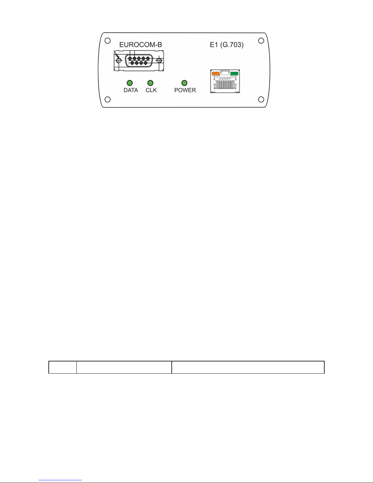
● EUROCOM (DSUB-9 connector) interface
● E1 (RJ-45 connector) interface
● 'Power' status indicator (LED)
● Received 'DATA' and 'CLK' signals indicators (LEDs) for EUROCOM
interface.
● Received E1 signal indicator (green LED on E1 connector)
● Received E1 G.704 frame synchronization status indicator (orange LED on E1
connector)
3. Rear panel layout
Rear panel contains:
● Power supply socket (depending on power supply version)
● RS-232 (DSUB-9 connector) interface
4. Connector layout
1. Interface E1 connector RJ-45
Pin Direction Function
1 input to converter Received Data – wire A
2 input to converter Received Data – wire B
3 not used
4 output from converter Transmitted Data – wire A
TEL-KA EUROCOM B / E1 Mux converter www.tel-ka.com.pl
User Manual v.3.1 4. Apr. 2014 Page 4/13
Page 5

5 output from converter Transmitted Data – wire B
6 not used
7 GND Shield - ground
8 GND Shield - ground
2. Eurocom B interface, connector DSUB-9/15 female (front panel)
No
DB9DB
15
Signal Name
Eurocom B
Direction RL-xxx
TDM connector
AN/GRC-xxx
Eurocom In/Out
1 1 4 Transmit Clock A
Output from
converter
L F
2 6 12 Transmit Clock B M E
3 2 1 Transmit Data A H H
4 7 9 Transmit Data B G G
5 3 7 Receive Clock A
Input to
converter
J S
6 8 15 Receive Clock B K R
7 4 3 Receive Data A F T
8 9 11 Receive Data B E J
9,105 2,6
8,14
GND Chassis V V
1. RL-xxx : Ericsson/Konsberg
2. AN/GRC-xxx : Marconi/Ultra
3. RS-232 interface, connector DSUB-9 female (rear panel)
Pin Function Direction
2 Received data From converter
3 Transmitted data To converter
5 Ground
4 RTS (used only during firmware update) To converter
7 DTR (used only during firmware update) To converter
TEL-KA EUROCOM B / E1 Mux converter www.tel-ka.com.pl
User Manual v.3.1 4. Apr. 2014 Page 5/13
Page 6

5. Power options
● DC 24V option
Converter box is powered by +12..+30VDC (non-isolated). The
equipment is resistant to incorrect power connection, if the voltage is
below 35V. Socket is PSU 5.5/2.5mm.
● DC 48V option
Converter box is powered by -36..-72VDC (isolated). The equipment is
resistant to incorrect power connection, if the voltage is below 100V.
Socket is MC 1,5/3-G-3.81.
● AC option
Converter box is powered by 85…240VAC, 47…63Hz, socket
IEC60320-C14
6. Configuration
1. Modes of operation
The converter offers three modes of operation:
● Simple converter mode
Simple interface converter 2048kbps only
● Multiplier mode
In this mode each bit received from Eurocom interface is transmitted 8,
4, or 2 by interface E1. In the direction from Eurocom interface to the E1
interface the degree of multiplication is determined automatically based
on measurement Eurocom interface received clock frequency. In the
opposite direction the equipment automatically recognized degree of
multiplication on E1 interface and retrieve the original binary stream on
Eurocom interface
● Multiplexer mode
For 2048kbps it works just like simple raw-data converter. For lessee
throughput, G.704 framing is generated on E1 interface and raw data
from Eurocom side are placed in predetermined timeslots (and viceversa). The byte integrity is not maintained (in the case of connecting
two E1 nodes through Eurocom link with throughput 256/512 or 1024
kbps).
2. How to set up
Connect the device to terminal through the serial interface. Set the
following parameters of the interface:
baud rate – 57600 bit/s
TEL-KA EUROCOM B / E1 Mux converter www.tel-ka.com.pl
User Manual v.3.1 4. Apr. 2014 Page 6/13
Page 7

character format – 8N2 (8 bit, 2 stop bits, no parity)
flow control – none
kind on terminal – ansi/VT100
As the terminal can be used PC with a serial interface and an appropriate
program such as Hyperterminal (under WindowsXP) or Putty (version 0.60
or higher). Then turn on the equipment and follow the instructions on the
screen. After about 10 second the device is ready to work with the last set
configuration.
3. Main menu
After power up the following screen appears:
The following options are available:
Check configuration – display current configuration
Check status – display current status
Set configuration – select this option to change current configuration
Set common parameters – set common parameters like PLL bandwidth
Load configuration from memory – use this option to restore previously
saved configuration
Save configuration to memory – use this option to write current
configuration to non-volatile memory. 64 different configuration identified
by name and number are possible.
Load default configuration – use this option to load one from fixed
configuration examples.
TEL-KA EUROCOM B / E1 Mux converter www.tel-ka.com.pl
User Manual v.3.1 4. Apr. 2014 Page 7/13
Page 8

* – entry into debug mode, do not use.
4. Check configuration menu (1)
After pressing key '1' the screen containing current configuration appears.
The following figures show examples of configurations (2048kbps raw data
and G.704 mode
TEL-KA EUROCOM B / E1 Mux converter www.tel-ka.com.pl
User Manual v.3.1 4. Apr. 2014 Page 8/13
Page 9

5. Check status menu
After pressing key '2' the following screen appears:
Above screen contains information about AIS (Alarm Indication Signal) on
both Eurocom and E1 inputs, measured Eurocom input clock frequency and
E1 framing synchronization status (in G.704 mode only). Pressing Enter
refresh the screen.
6. Select configuration menu
New configuration is entered by pressing key 3. After pressing this key in
the main menu the following screen appears:
TEL-KA EUROCOM B / E1 Mux converter www.tel-ka.com.pl
User Manual v.3.1 4. Apr. 2014 Page 9/13
Page 10

On the top of the screen the current mode is displayed. By pressing keys '1',
'2' or '3' the new configuration may be introduced. The selection is
confirmed by pressing Enter. The next screen depends on selected
configuration.
● 2048kbps raw data mode
For this mode there is only one screen.
● G.704 mode
The next screen allows throughput selection:
On the top of the screen the current throughput is displayed. By pressing
keys '1', '2' or '3' the new throughput may be introduced. The selection is
confirmed by pressing Enter. Then the next screen with G.704 frame
parameters is displayed:
TEL-KA EUROCOM B / E1 Mux converter www.tel-ka.com.pl
User Manual v.3.1 4. Apr. 2014 Page 10/13
Page 11

On the top of the screen current frame parameters are displayed. By
pressing keys '1' … '8' the indicated bits may be changed. The selection
is confirmed by pressing Enter. In the next step the slot maps is selected:
The current occupied slots map is displayed on the top (occupied slots
are marked by X). By pressing key '1' and next the Enter the default map
is selected. Pressing key '2' allows arbitrary slot origin selection. Enter
the first slot number and confirm the selection by pressing Enter.
● Multiplier mode
TEL-KA EUROCOM B / E1 Mux converter www.tel-ka.com.pl
User Manual v.3.1 4. Apr. 2014 Page 11/13
Page 12

For this mode is only one screen.
7. Set Common Parameters menu
After pressing key '4' the following screen appears:
It is possible to change the following parameters:
- wide/narrow bandwidth of PLL's
- transmitters enable mode
Last parameters are important only in certain modes
8. Load configuration from memory menu
This option allows loading the previously saved configuration from the non
volatile memory.
9. Save configuration to memory menu
It is possible to save current configuration in the nonvolatile memory for later
use.
TEL-KA EUROCOM B / E1 Mux converter www.tel-ka.com.pl
User Manual v.3.1 4. Apr. 2014 Page 12/13
Page 13

10. Load defaults configuration menu
The set of typical configuration is prepared:
By pressing one of the keys '1' … '5' the one of tipical configuration is
introduced.
11.Converter board removal
1. Plug off power supply cable
2. Unscrew four screws holding rear panel
3. Unscrew four screws holding front panel
4. Disconnect flat cable from board
5. Pull out converter board in rear panel direction
12.Firmware upgrade
Follow the instruction that came with new version of firmware
TEL-KA EUROCOM B / E1 Mux converter www.tel-ka.com.pl
User Manual v.3.1 4. Apr. 2014 Page 13/13
 Loading...