

EUROCOM 8500-C DeskNote, 8500-M DeskNote, 8500-P DeskNote Plus, 8500-P3 DeskNote Plus, 8500-SE Supernotebook User Manual
...Page 1

EUROCOM 8500 DeskNote
User’s Manual
This manual covers EUROCOM 8500P, 8500P3 and 8500C DeskNote™
models. All distinctions between models are covered throughout this
manual. Enjoy your EUROCOM 8500 DeskNote.
Notice
The company reserves the right to make an y updates revisions or changes
to the information contained herein as and when deemed necessary. The
company is under n o obligation to not ify any purchaser or end-user of such
actions in advance or afterwards .
1999
Trademarks
DeskNote is a registered trademark of Eurocom Corporation
IBM PC, OS/2, PS/2, EGA, and VGA are registered trademarks of
International Business Machines Corporation.
Intel, Pentium are registered trademarks of Intel Corporation.
MS-DOS, Microsoft Windows, Windows NT and Microsoft Mouse are
registered trademarks of Microsoft Corporation.
Sound Blaster Pro is a registered trademark of Creative Labs, Inc.
SystemSoft is a registered trademark of SystemSoft Corp.
Other brand and product names are registered trademarks of their
respective companies.
Page 2

Table of Contents
CHAPTER 1 : GETTING STARTED.................................................................1-1
NPACKING THE DESKNOTE
U
POWERING THE SYSTEM
!
.............................................................................1-2
...................................................................................1-3
AC Power Adapter...........................................................................................1-3
Battery Pack.....................................................................................................1-4
Inserting................................................................................................................... 1-4
Removing................................................................................................................. 1-4
Recharging by AC Power......................................................................................... 1-5
Proper Handling of the Battery Pack........................................................................ 1-5
OPENING THE
!
LCD C
OVER
..............................................................................1-6
LED Indicators on the LCD Cover..................................................................1-7
TOP-FRONT VIEW
!
............................................................................................1-8
LCD Panel .......................................................................................................1-8
Stereo Speakers................................................................................................1-8
Trackpad and Buttons......................................................................................1-8
Keyboard..........................................................................................................1-8
Microphone..................................................................................................1-8
System Status LED Indicators.........................................................................1-9
Power Button...................................................................................................1-9
REAR VIEW
!
RIGHT-SIDE VIEW
!
LEFT-SIDE VIEW
!
....................................................................................................1-11
..........................................................................................1-13
............................................................................................1-15
5.25” CD-ROM Drive ...................................................................................1-15
Infrared..........................................................................................................1-15
Left-side Stand...............................................................................................1-16
CHAPTER 2 : OPERATION............................................................................. 2-17
UPGRADING PROCESSOR MODULE
!
ON
EUROCOM 8500P/3 D
ESKNOTE
.................................................................2-18
™.............................................................2-18
Replacing Processor Module.........................................................................2-19
UPGRADING PROCESSOR MODULE
!
ON DESKNOTE
8500C ........................................................................................2-20
.................................................................2-20
Replacing Processor Module.........................................................................2-20
SETTING
!
DIP S
WITCH
....................................................................................2-23
Accessing DIP Switch (SW1)........................................................................2-23
EXP ANDING MEMORY
!
....................................................................................2-25
Accessing the Memory Sockets.....................................................................2-26
Installing Memory Module............................................................................2-27
Removing Memory Module...........................................................................2-28
USING HARD DISK DRIVE
!
..............................................................................2-29
Page 3

Removing.......................................................................................................2-29
Replacing Hard Disk Drive............................................................................2-30
USING FLOPPY DISK DRIVE
!
...........................................................................2-31
Inserting/Removing Diskettes........................................................................2-31
Replacing Floppy Disk Drive........................................................................2-32
USING
!
CD-ROM............................................................................................2-33
Removing CD-ROM Module........................................................................2-34
Loading Compact Discs.................................................................................2-35
Handling of Compact Discs ...........................................................................2-36
USING
!
ARD SOCKETS
PC C
.............................................................................2-37
Inserting PC Cards.........................................................................................2-38
Removing PC Cards.......................................................................................2-38
USING HOT KEYS
!
...........................................................................................2-39
Windows 95 Special Keys.............................................................................2-40
USING NUMERIC KEYPAD
!
USING POWER MANAGEMENT
!
..............................................................................2-41
........................................................................2-42
Advanced Power Management (APM 1.2)....................................................2-42
Global Standby..............................................................................................2-42
Hard Disk Standby.........................................................................................2-42
Suspend and Resume.....................................................................................2-43
Powered On Suspend (POS).................................................................................. 2-43
Resume from POS Mode ....................................................................................... 2-43
Suspend To Disk (STD)......................................................................................... 2-44
Resume from STD Mode....................................................................................... 2-44
ATTACHING PERIPHERAL DEVICES
!
................................................................2-45
Attaching a Security Lock .............................................................................2-45
Attaching a Parallel Printer............................................................................2-46
Attaching a TV Set ........................................................................................2-47
Attaching a Video Input Device.....................................................................2-48
Attaching a USB-compatible Device.............................................................2-49
Attaching a Serial Mouse...............................................................................2-50
Attaching an External Monitor (CRT)...........................................................2-51
Attaching a PS/2 Keyboard or Mouse............................................................2-52
Attaching a Digital Camera ...........................................................................2-53
CHAPTER 3 : BIOS UTILITIES...................................................................... 3-54
POWER ON SELF TEST
!
(POST).......................................................................3-55
POST Message: Normal Operation ...............................................................3-55
POST Message: Error Detected.....................................................................3-56
SYSTEM CONFIGURATION UTILITY
!
.................................................................3-57
Information in the System Configuration Utility...........................................3-57
Initiating the System Configuration Utility ...................................................3-58
Working with the Menu Bar ..........................................................................3-59
Page 4

Working with the Pull-down Menu................................................................3-60
Features of the System Configuration Utility ................................................3-61
Startup Menu ......................................................................................................... 3-61
Memory Menu....................................................................................................... 3-63
Disks Menu............................................................................................................ 3-64
Components Menu................................................................................................. 3-65
Power Menu........................................................................................................... 3-68
Exit Menu.............................................................................................................. 3-71
CHAPTER 4 : TROUBLESHOOTING............................................................. 4-1
BATTE RY
!
POWER
!
HARD DISK DRIVE
!
FLOPPY DISK DRIVE
!
HARDWARE INST ALLA TION
!
!
LCD P
MEMORY MODULE
!
!
PC C
BOOT PASSWORD
!
AUDIO
!
!
CD...................................................................................................................4-8
PRINTER
!
!
ATI DVD P
..........................................................................................................4-2
.............................................................................................................4-3
...........................................................................................4-3
........................................................................................4-4
..............................................................................4-4
ANEL
.....................................................................................................4-5
...........................................................................................4-6
ARD
.........................................................................................................4-6
.............................................................................................4-7
..............................................................................................................4-7
...........................................................................................................4-9
LA Y (OPTION
) ................................................................................4-9
CHAPTER 5 : INSTALLING DRIVERS......................................................... 5-10
INSTALLING WINDOWS
!
INSTALLING WINDOWS
!
INSTALLING DRIVERS IN WINDOWS
!
95..............................................................................5-11
98..............................................................................5-13
95...........................................................5-14
Step 1: Installing USB Driver........................................................................5-14
Step 2: Installing TXPATCH Driver..............................................................5-14
Step 3: Installing VGA Driver.......................................................................5-14
Step 4: Installing Audio Driver (1978S M2E)...............................................5-15
Step 5: Installing PCMCIA driver.................................................................5-15
Step 6: Installing Video-in Driver..................................................................5-16
Step 7: Installing ATI DVD Play Driver (Option).........................................5-16
Step 8: Using Infrared Wireless Communication...........................................5-16
INSTALLING DRIVERS IN WINDOWS
!
NT 4.0 ...................................................5-17
Step 1: Installing VGA Driver.......................................................................5-17
Step 2: Installing Audio Driver (1978S M2E)...............................................5-17
INSTALLING DRIVERS IN WINDOWS
!
98...........................................................5-18
Step 1: Installing VGA Driver.......................................................................5-18
Step 2: Installing Audio Driver (1978S M2E)...............................................5-18
Step 3: Installing PCMCIA Driver ................................................................5-19
Page 5

Step 4: Installing Video-in Driver..................................................................5-19
Step 5: Installing ATI DVD Play Driver (Option).........................................5-19
APPENDIX A: SPECIFICATIONS.......................................................................V
Page 6
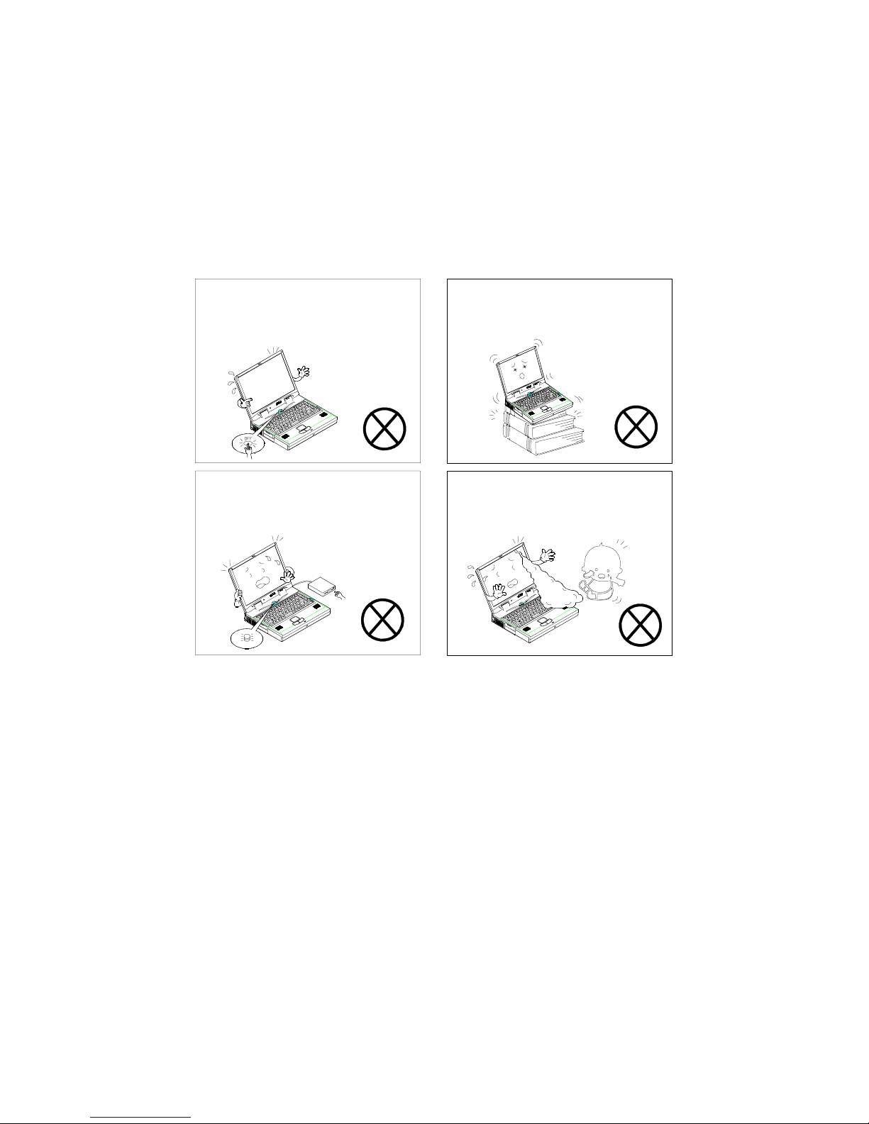
Safety Notice
The computer is a delic ate de vic e tha t req uir es c areful handling. Negl ig enc e
or mistaken use m ay cause serious damage. Bef ore you lear n to operate or
use this computer, you need to understand the instruction regarding safet y
handling.
The following mentions the incorrect handling that is ser iously inhibited. To
keep the computer f rom being damaged, please k eep these precautions i n
mind.
Do not turn off the power during
operation.
Do not turn off the peripheral device
when the light is on.
Do not place the computer on an
unstable surface.
Do not touch the poisonous liquid
when the LCD is broken.
Page 7
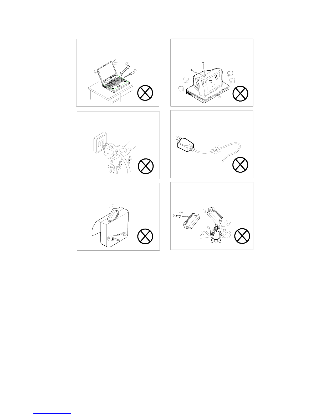
Do not disassemble the computer
yourself.
Do not place anything heavy on the
computer.
Do not touch power cord with a wet
hand.
Keep the computer away from any
metal appliance.
Do not use a broken power cord.
Do not throw the computer or
accessories into fire.
Page 8
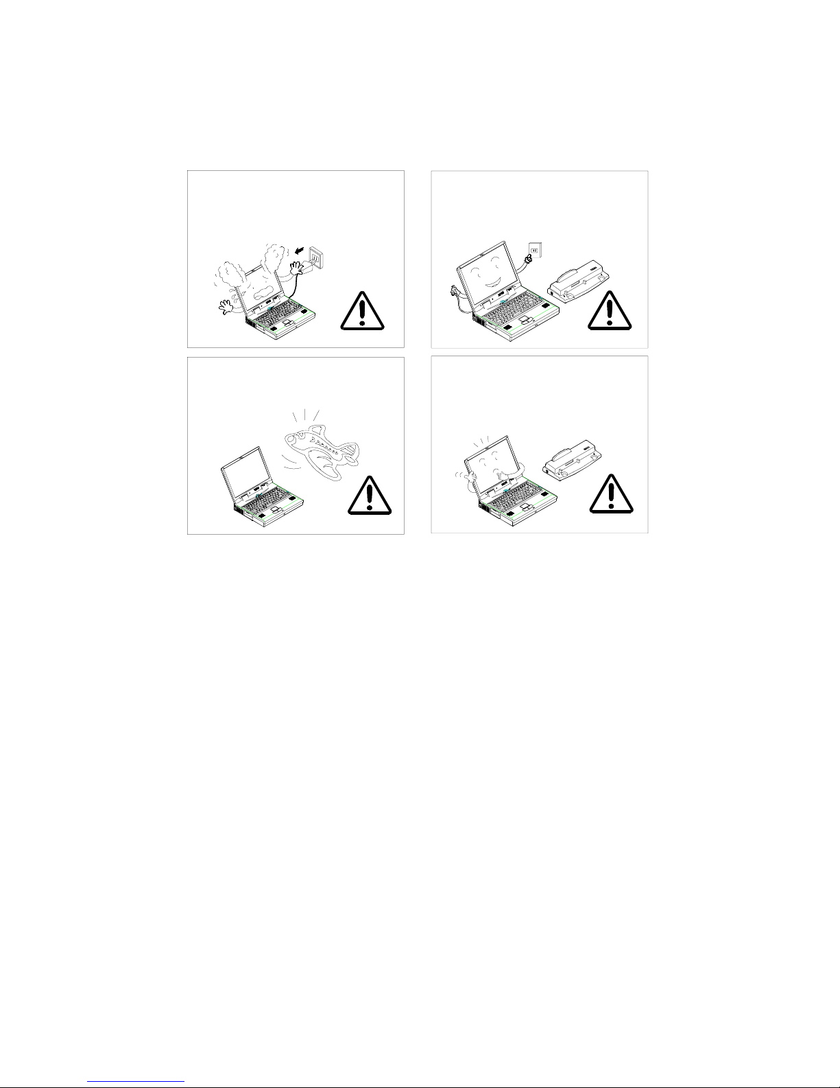
The following mentions the acti ons that are im portant for your Desk Note. To
keep your DeskNote in excellent condition, please f ollow the instruction as
much as possible.
If there is unusual odor, heat or smoke,
unplug the power cord immediately.
Follow the airline instructions when
traveling with your DeskNote
.
Unplug the power cord when attaching
peripheral device.
Use the appropriate accessory model
of peripheral device for your
DeskNote
.
Page 9
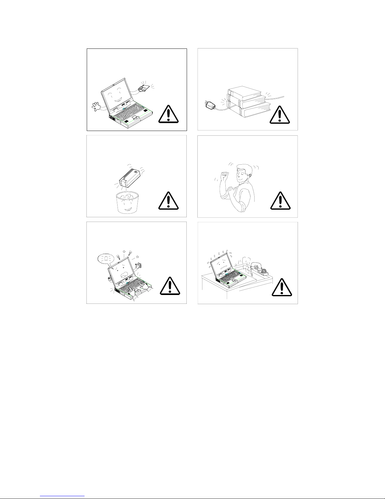
Maintain your computer regularly.
A
r
Do not place heavy things on the
power cord.
ffix tape to the contact plate while
putting the battery into keeping box.
The data is easy to lose in low powe
status.
Take a rest after a long time of work.
Please keep the computer away from
humid environment.
Page 10

Conventions
This manual uses the following conventions to describe, identify, and
highlight terms and operating procedures.
Text Conventions
Text in boldface contains messages that are important for safe operation.
Please read.
Characters in boldface repres ent specific items or keys, e.g.
key.
File names are presented in bold capitals, e.g.
Abbreviations
For the purpose of clarity, abbreviations are enclosed in parentheses
following their definition; for example, Enhanced Parallel Port (EPP) mode.
Icons
Icons identify ports and jack s of the Des kNote com puter. The system status
indicators are also identified with their relative icons.
Keys
Keys appear in boldface. A plus sign ( +) between two keys indicates that
they should be pressed simultan eously.
Messages
Note
: A note is an advice that helps you make best use of your
DeskNote
computer. Please read.
A:\>0VMAKFIL —Pn
CardBus, Fn
.
Page 11
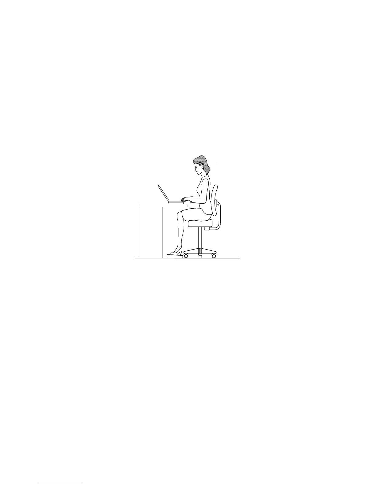
Ergonomics
Developing good work habits are important if you need to work in front of
your DeskNote
discomfort or serious injury from repetitive strain to your hands, wrists or
other joints. The following are some tips to reduce the strain:
Adjust the chair and des k to make your elbo w height near th e height of
"
keyboard. Keep your forearms, wrists, and hands in a relaxed position.
Your knees should be sli ghtly hi gher tha n your hips. Plac e your feet flat
"
on the floor or on a footrest if necessary.
Use a chair with a back and adjust it to support your lower back
"
comfortably.
Sit straight so that your k nees, hips and elbo ws form approxim ately 90°
"
angles when you are working.
for long periods of time. Improper work habits can result in
Page 12

Lighting
Proper lighting and comfortable display viewing angle can reduce the eye
strain and muscle fatigue in your neck and shoulders.
Position the displa y to avoid glare or reflections from overhead lighting
"
or outside light sources.
Keep the display screen clean and set the brightness and contrast to
"
levels that allow you to see the screen clearly.
Position the display directly in front of you at a comfortable viewing
"
distance.
Adjust the display-viewing angle to find the best position.
"
In addition, continuous concentration on computing work can result in
discomfort and injury. Remember to:
Alter your posture frequently.
"
Stretch and exercise your body several times a day.
"
Take periodic breaks when yo u work at the computer f or long per iods of
"
time. Frequent and s hort breaks are of greater benef it than fewer and
longer breaks.
Page 13

Chapter 3: BIOS Utilities 1-1
Chapter 1 : Getting Started
This chapter provides you with the introduction to the DeskNote
Computer. It will familiarize you to the DeskNote’s features, components,
operating environment and the power sources.
!
Unpacking your DeskNote
!
Features of the DeskNote
!
Operating environment
!
Powering the system
Page 14
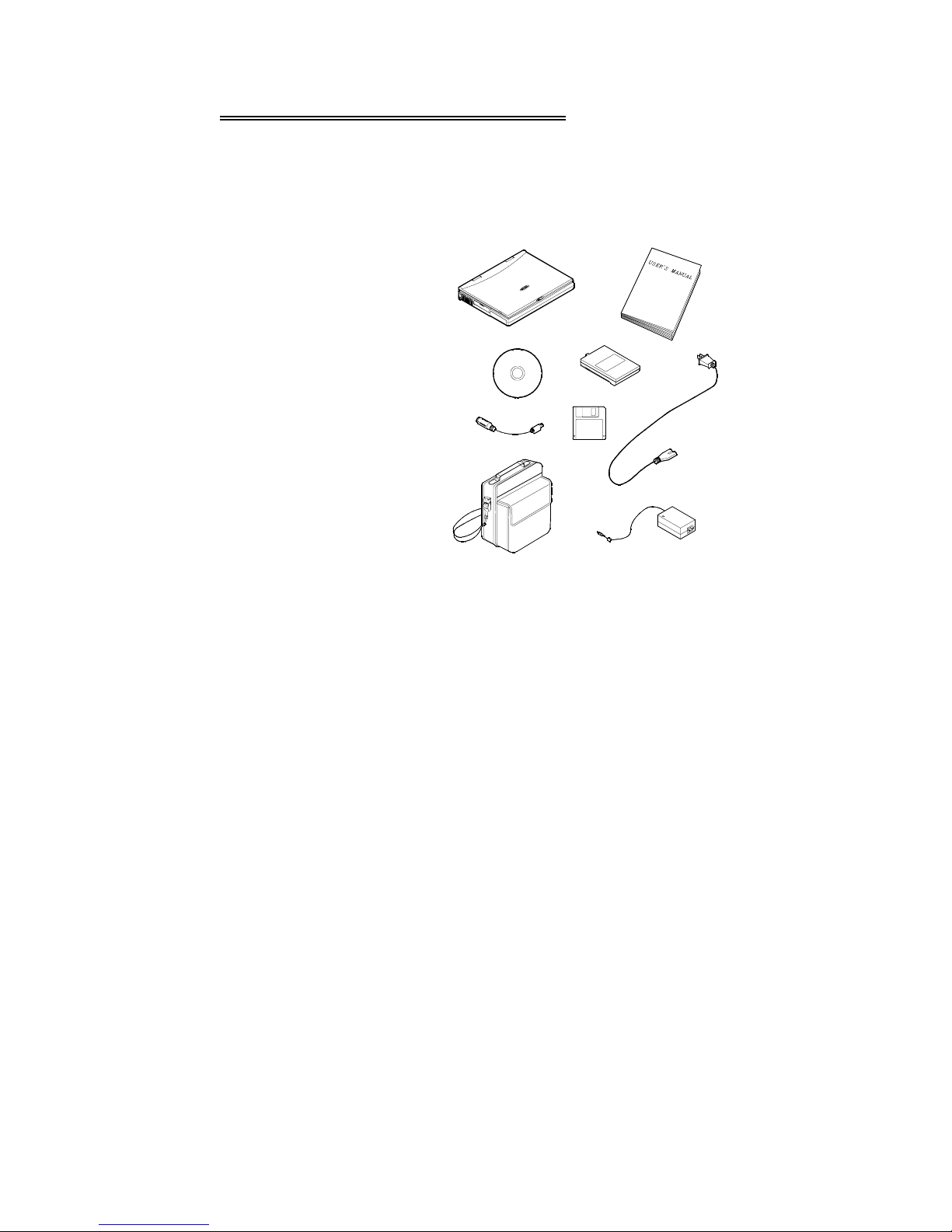
Unpacking the DeskNote
Carefully unpack the DeskNote Computer and the included accessories
(Figure 1-1). If there is any discrepancy or problem, contact your dealer
immediately. Be sure to save the pack ing materials in the e vent that the
DeskNote needs to be shipped in the future. The shipping carton should
contain the following items:
❍ DeskNote computer
❍ CD with Drivers/Manuals
❍ PS/2 Y-Cable
❍ Carrying Bag
❍ Battery Pack
❍ Utilities Diskette
❍ Power Cord
❍ Power Adapter
Figure 1-1
Page 15
Chapter 3: BIOS Utilities 1-3
Powering the System
!!!!
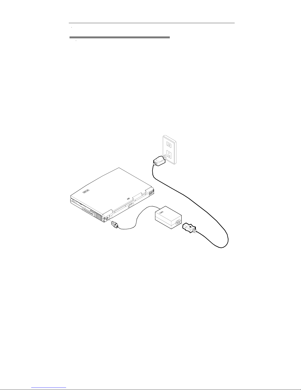
You can use the AC power adapter or batter y pack to power the com puter
system.
AC Power Adap ter
Use only the power adapter that comes with your computer. An incorrect
type of power adapter will cause damage to the computer and its
components.
1.
Plug the power adapter cord int o the AC- in soc k et on the re ar pa nel of
the computer.
2.
Connect the power adapter with the power cord.
3.
Plug the power cord into a properly grounded outlet (Figure 1-3).
4.
Refer to Chapter 1, System Status LED Indicators for more information
on system power status.
Figure 1-3
Page 16
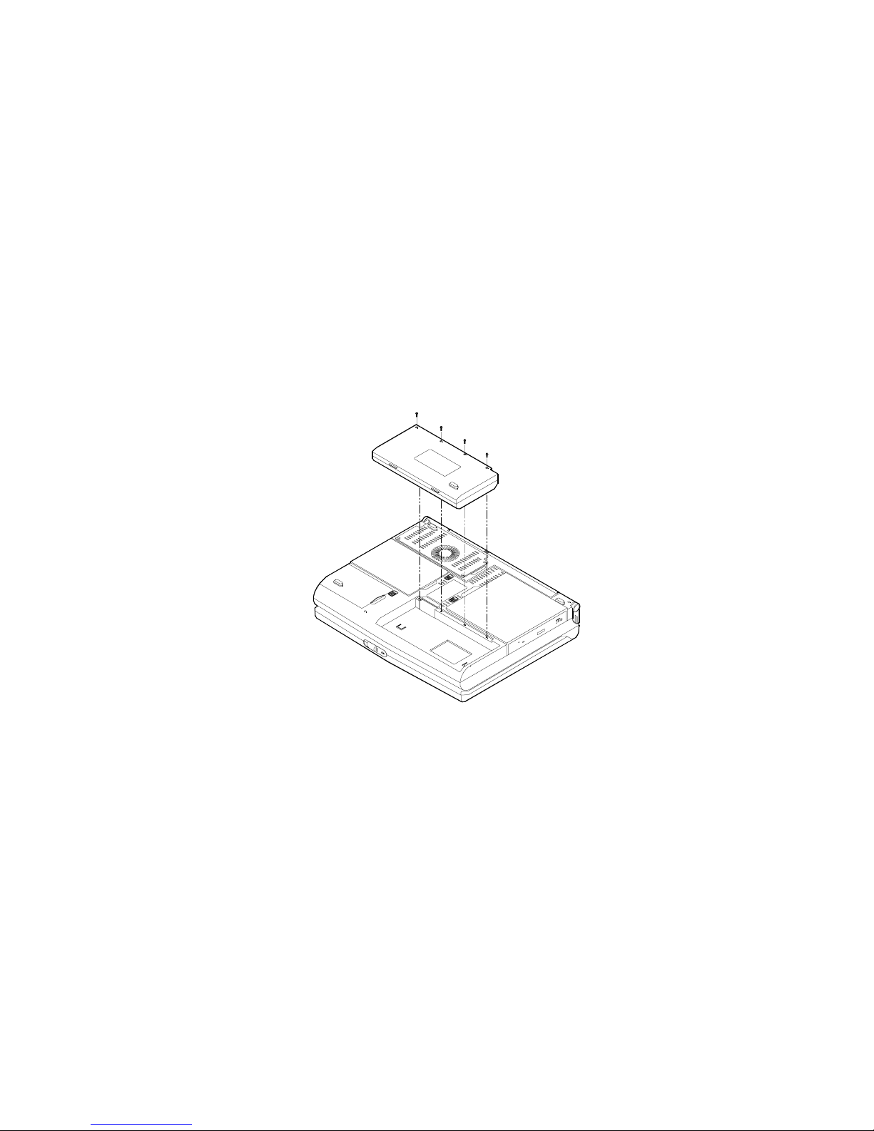
Battery Pack
The battery pack provides power f or continuous portable operation of the
computer. When using the battery no external power source is required.
The actual operation t ime is related to the applic ation and the conf iguratio n
you’re using.
Inserting
1.
Turn the computer over.
2.
Fit the battery pack firmly at a slight angle into the computer.
3.
Install the four screws to fasten the battery pack (Figure 1-4).
Removing
1.
Turn the computer over.
2.
Remove the four screws that fasten the battery pack.
3.
Carefully lift the battery pack from the computer.
Figure 1-4
Page 17

Chapter 3: BIOS Utilities 1-5
Recharging by AC Power
The battery pack can be recharged when the computer is connected to
power supply with the AC adapter, when the system is in operation or not.
•
Connect the computer to the power supply with AC adapter to begin
charging system’s battery pack. You do not need to turn off the
DeskNote’s power.
•
Allow few (up to 5) hours to fully recharge the battery pack.
•
Please refer to Chapter 1, System Status LED Indicators for more
information on battery charge status.
Proper Handling of the Battery Pack
•
Do not attempt to disassemble the battery under any circumstances.
•
The battery may explode if exposed to fire or high temperatures.
•
Avoid battery short circuit by preventing contact from the metal
terminals (+, -).
Page 18
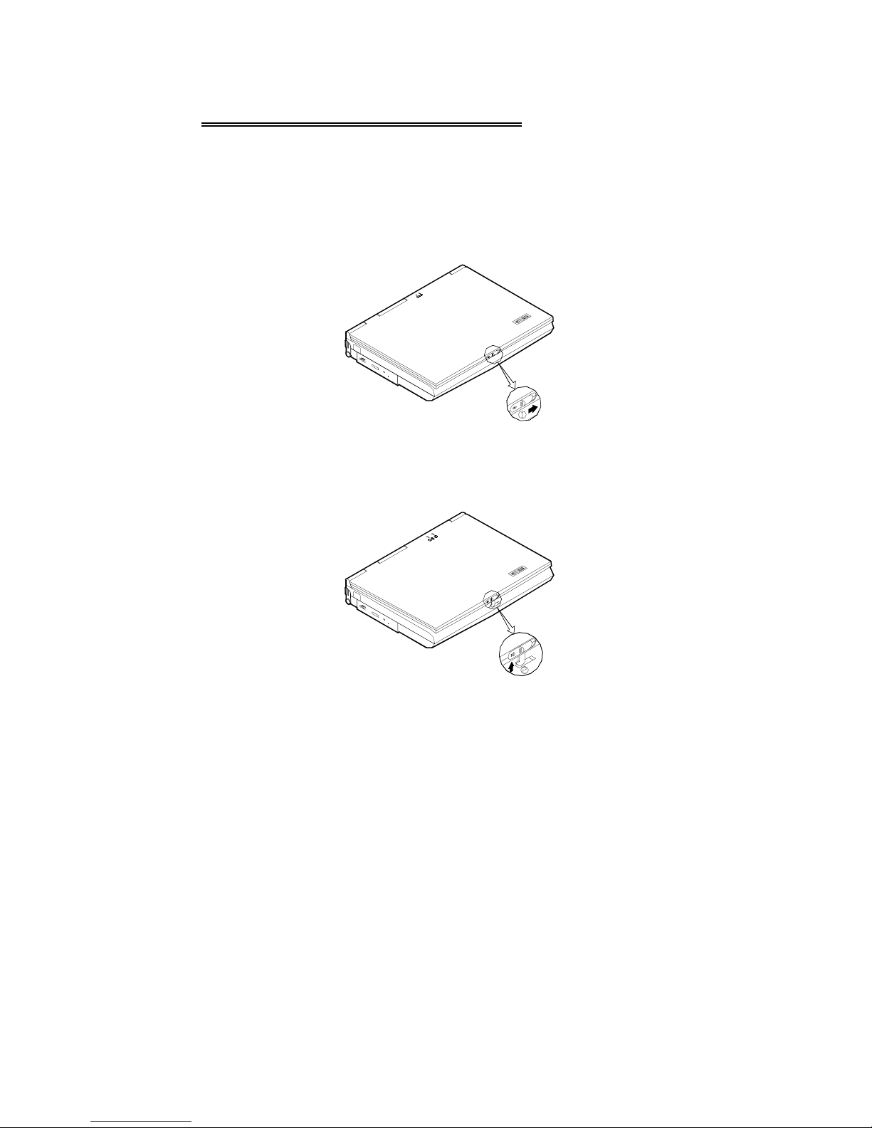
Opening the LCD Cover
!!!!
1.
Move the latch to the right to release the top cover. (Figure 1-5).
2.
Lift the top cover to reveal the LCD panel and keyboard (Figure 1-6).
3.
Adjust the LCD panel to a comfortable viewing angle.
4.
Press the power button to turn the system on or off (refer to Chapt er 1,
Top-Front View for more information of the power button).
Figure 1-5
Figure 1-6
Page 19
Chapter 3: BIOS Utilities 1-7
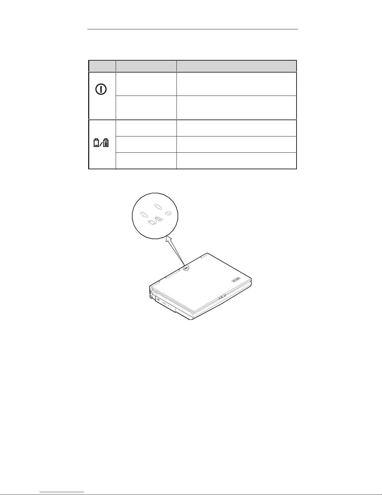
LED Indicators on the LCD Cover
Icon Color Description
Green Battery power is used with system turning
Red AC power is used with system turning
Green Battery is fully charged.
on.
on.
Red Battery is being charged.
Blinking Red Battery power is critica lly low.
Figure 1-7
Page 20

Top-Front View
!!!!
LCD Panel
The EUROCOM 8500 DeskNote provides you with a large 15 .1” T FT
LCD panel. The LCD pane l is driven b y a AGP bus video controller
with 8 MB video memory.
Stereo Speakers
Two built-in speakers provide clear stereo sound.
Trackpad and Buttons
The pointing device features a sensitive glide pad for precise
movements. It functions like a two-button mouse does. The right
trackpad button is equivalent to the right mouse button; the left
trackpad button is equivalent to the left mouse button.
Keyboard
The computer features a 102-key Windows 95 keyboard that is
integrated with the numeric keypad. It is detachable for various
language versions. You may refer to Chapter 2: Operatio n for more
information.
Microphone
This is the built-in microphone.
Page 21
Chapter 3: BIOS Utilities 1-9
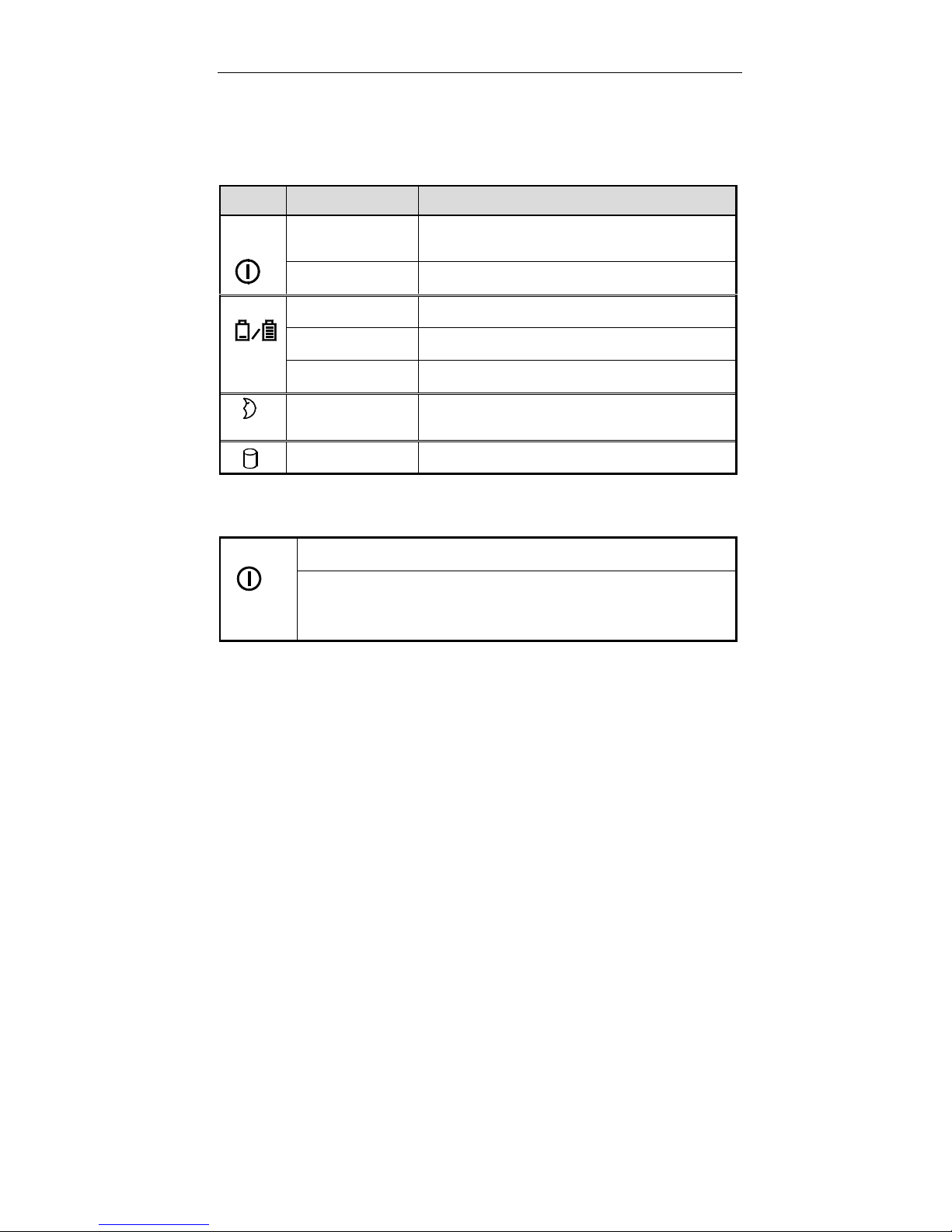
System Status LED Indicators
The LED indicators display the system’s operation status.
Icon Color Description
Green Battery power is used with system turned
on.
Red AC power is used with system turned on.
Green Battery is fully charged.
Red Battery is being charged.
Blinking Red Battery power is critica lly low.
Green The system has entered the configured
suspend mode (either POS or STR mode).
Green The hard disk is being accessed.
Power Button
Use this button to turn the system on or off.
Note:
again.
After proper configuration under SCU, this button can be
used as suspend/resume hot button (refer to Chapter 3:
BIOS Utilities, Power Menu for more information).
After turning off the system, wait for a few seconds to power it on
Page 22
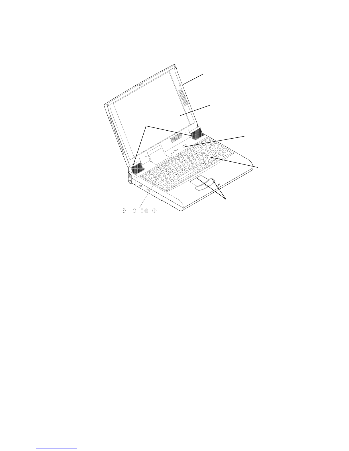
p
Stereo Speakers
Microphone
LCD Panel
Power Button
Keyboard
Status LED Indicators
Figure 1-8
Track
ad and Buttons
Page 23

Chapter 3: BIOS Utilities 1-11
Rear View
!!!!
AC-in Socket
Plug the AC adapter into this socket for power supply. To
disconnect, pull the plug (not the cord) directly back.
Security Connector
The Security Connec tor is used to protect your computer from
being stolen. Wrap the steel cable around your desk. Then,
insert the locking device into this security connector.
Parallel Port
This parallel port supports EPP (Enhanced Parallel Port) and
ECP (Extended Capabilities Port) modes.
S-Video Jack
Use this jack to transmit video signal to a TV set. You may
need to select the video standar d (NTSC/PAL) for video displa y
(please refer to Chapter 3, Components Menu for more
information).
RCA Jack
This jack ac cepts analog c ompos ite signals f rom external video
devices, e.g. camera, CD.
Expansion Port
This port is used to connect the proprietary Port Replicator.
Dual USB Ports
The dual Universal Serial Bus (USB) ports simplify the
expansion capability for peripheral devices.
Serial Port
This port is UART 16C550 compatible. It features a 9-pin
connector for the addition of an external mouse for example.
Page 24
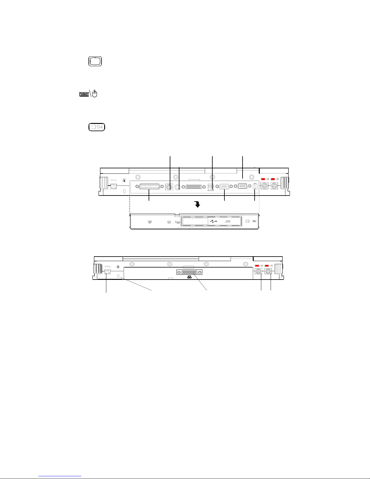
External Monitor (CRT) Port
This port is used f or transmission of the disp lay to an extern al
monitor. Simultaneous display with the LCD panel is available.
Dual PS/2 Type Ports
A PS/2 type mouse and keyboard can be connected to the
system using these ports. However, you cannot connect the
same type of PS/2 devices to both ports simultaneously.
1394 Port (8500P model only)
A newly developed port which connects with the digital camera.
USB PortsS-Video Jack CRT Port
RCA JacK
AC-in socket
Parallel Port
Figure 1-9
Security connector PS/2 type portsExpansion port
Figure 1-10
Serial Port 1394 Port
Page 25

Chapter 3: BIOS Utilities 1-13
Right-Side View
!!!!
PC Card Sockets
One Type III or two Type II PC cards can be used. Both
sockets will expand the system capabilities when a PC card is
inserted. To eject the PC card, press the appropriate eject
button (Figure 2-15).
2.5” Hard Disk Drive
The 2.5” hard disk drive is removable. It accepts any 2.5”
IDE hard disk drive with a height of 12.7mm or less. Ref er to
Chapter 2: “Operation” for more information.
3.5” Floppy Disk Drive
The computer comes standard with a 1.44MB floppy drive
installed. Press the button on its top-right side to eject the
diskette. The floppy disk module can be replaced with
additional drive un its , s uch as a secondar y 2.5 ”/ 3.0 ” hard disk
drive or Zip drive (Refer to Chapter 2: Operation for more
information).
Speaker-out Jack
Headphone and speakers can be attached to the system
through this jack.
Line-in Jack
External audio source ca n be fed into the computer through
this jack.
Microphone-in Jack
Use this jack to connect a microphone to the system.
Page 26

Ventilation
p
p
ppy
The computer vents were designed to help dissipate system’s
heat produced during norm al operation. Do not block or obs truct
vents while DeskNote ™ is in use.
Right-side Stand
Move this stand (tog ether with the left one) to adjus t the typing
angle. If a high speed C PU is installed, erect ing the stands on
both sides will be n ecessary for heat dissipat ion during operation
-
PC Card Socket
3.5” Flo
2.5” Hard Disk Drive
S
eaker-out
Disk Drive
Figure 1-12
Line-in
Micro
Right-side stand
Ventilation
hone-in
Page 27

Chapter 3: BIOS Utilities 1-15
Left-Side View
!!!!
5.25” CD-ROM Drive
The 5.25” IDE CD-ROM module is designed to be removable. The
eject button is located in the middle of the f ront c ov er of the CD-ROM
drive. Pressing it will release the CD tray.
Infrared
The system adopts infrared technology as the interface for simple,
fast and convenient data exchange f rom the computer to a n infr aredcompatible device. It implements IrDA (HPSIR), Amplitude Shifted
Keyed IR (ASKIR), and Fast IR (FIR). N o object should be bloc king
the line of sight between the computer and the infrared-equipped
device. For further information, please refer to the manual of the
wireless device you wish to connect on how to use the point-andshoot operation.
Page 28
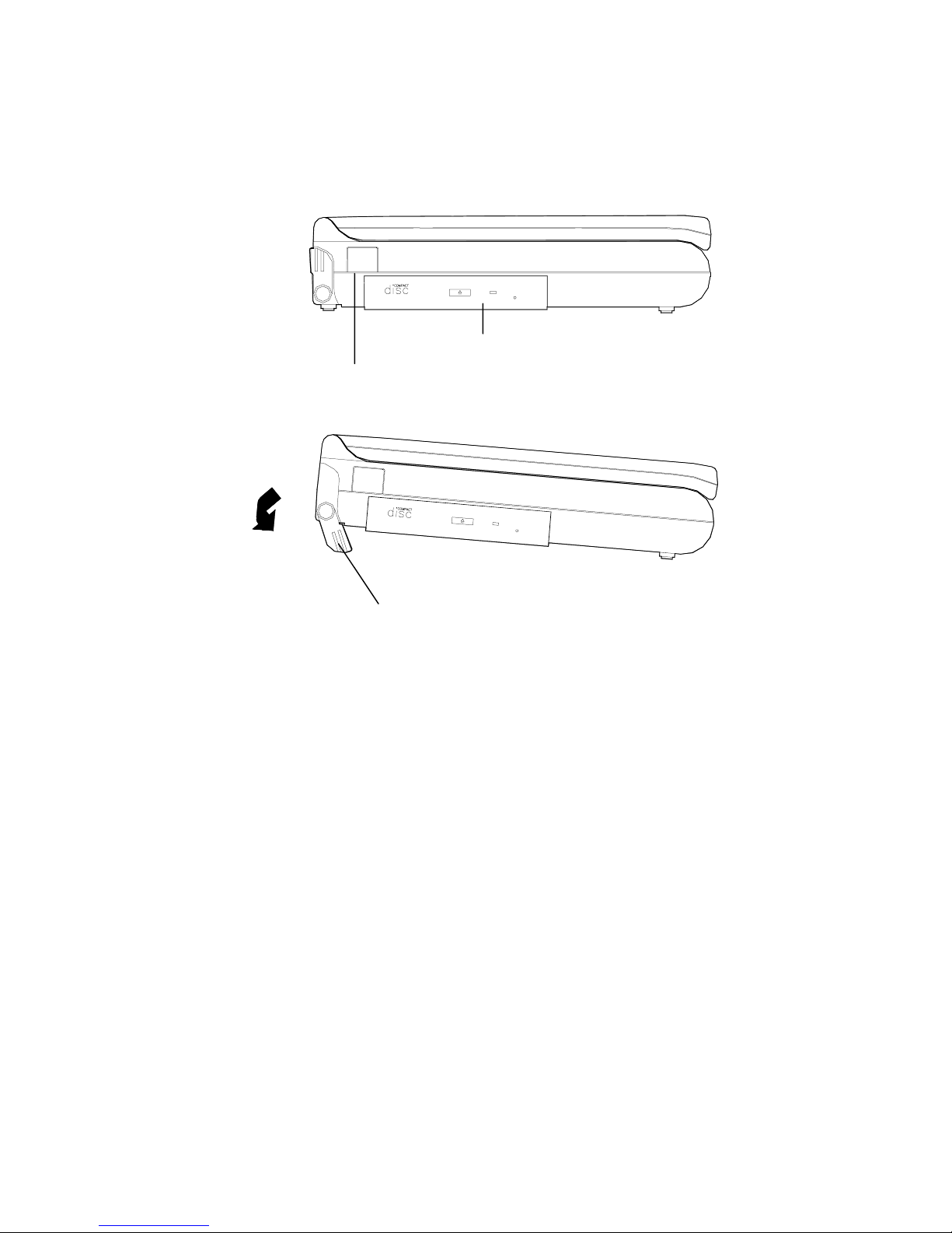
Left-side Stand
Move this stand (together with the right one) to adjust the typing
angle. If a high speed C PU is installed on the system, erec ting the
stands on both sides will be necessary for heat dissipation during
operation (Figure 1-14).
CD-ROM Drive
Infrared
Left-side Stand
Figure 1-13
Figure 1-14
Page 29

Chapter 3: BIOS Utilities 2-17
Chapter 2 : Operation
Your EUROCOM 8500 Desk Note has man y advanced featur es to help you
with your computer wor k. This chapter describes each of the computer’s
hardware features and shows you how to use them.
We strongly discourage EUROCOM DeskNote ™ owners from
servicing their systems. Serv ice by untrained indiv idual might result
in serious damage to components inside DeskNote. Opening
EUROCOM DeskNote™ might result in voiding warranty.
Before you begin working with the internal components of the computer,
remove the battery and disconnect the AC power adapter.
Make sure you wear an anti-static wrist strap to ground yourself before
working with or repair the internal components. Static electricity may
damage the components.
Upgrading Processor Module
!
Setting DIP Switch
!
Expanding Memory
!
Using Hard Disk Drive
!
Using Floppy Disk Drive
!
Using CD-ROM
!
Using PC Card Sockets
!
Using Hot Keys
!
Using Numeric Keypad
!
Using Power Management
!
Attaching Peripheral Devices
!
Page 30
Upgrading Processor Module
!!!!
on EUROCOM 8500P/3 DeskNote™
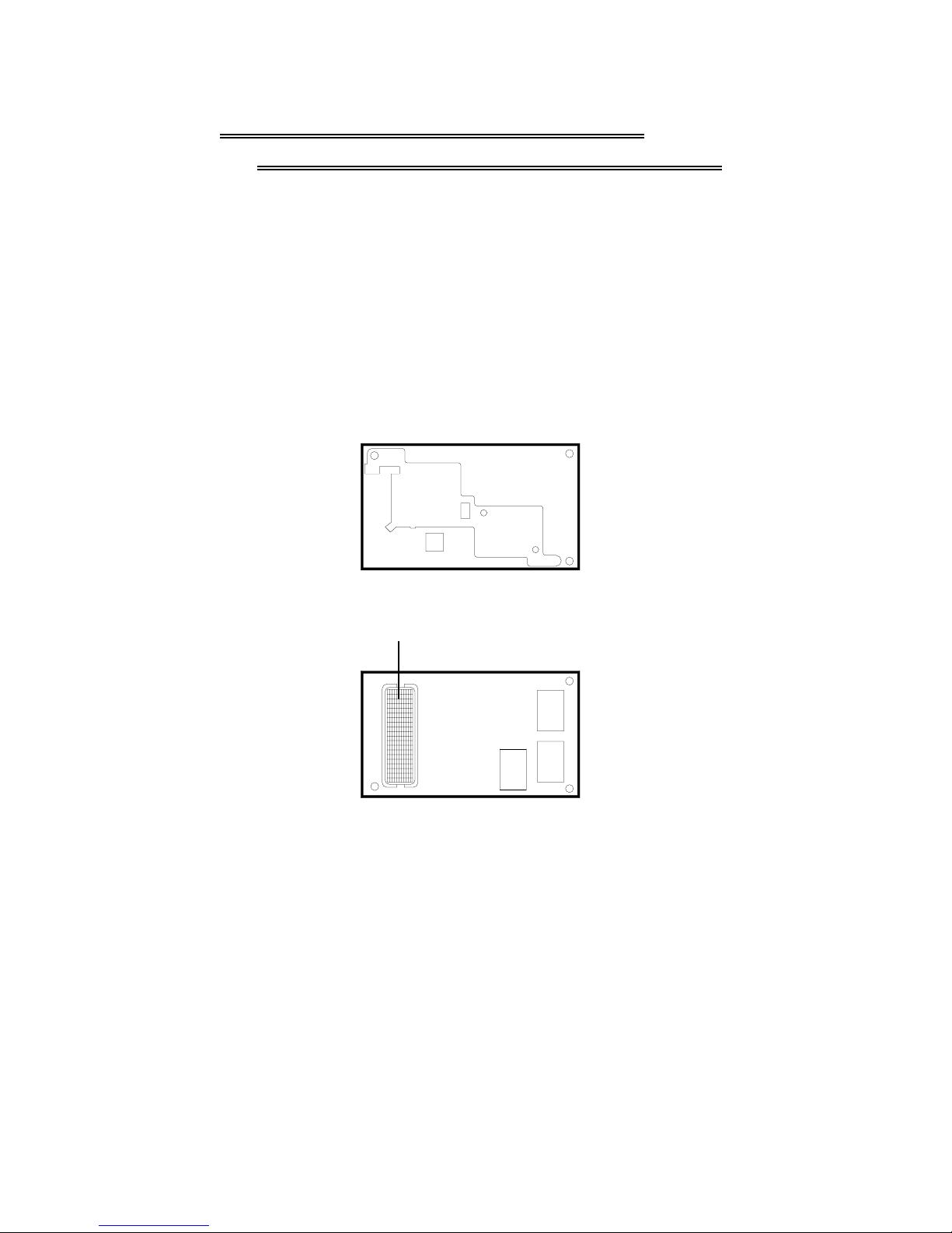
The DeskNote computer features the structure of Intel’s Mobile Module
(MMC2). The Processor Module incorporates an Intel Pentium Mobile
processor, secondary cache, and the Intel PCI set “Northbridge” system
controller, voltage regulator, and thermal s ensor on a single prin ted circuit
board.
The Processor Module is c onnected to the m ainboard th rough a connector.
This design facilitates users to easily upgrade their system by simply
replacing the Processor Module.
View from Top
Connector
View from Bottom
Figure 2-1
Page 31
Chapter 3: BIOS Utilities 2-19
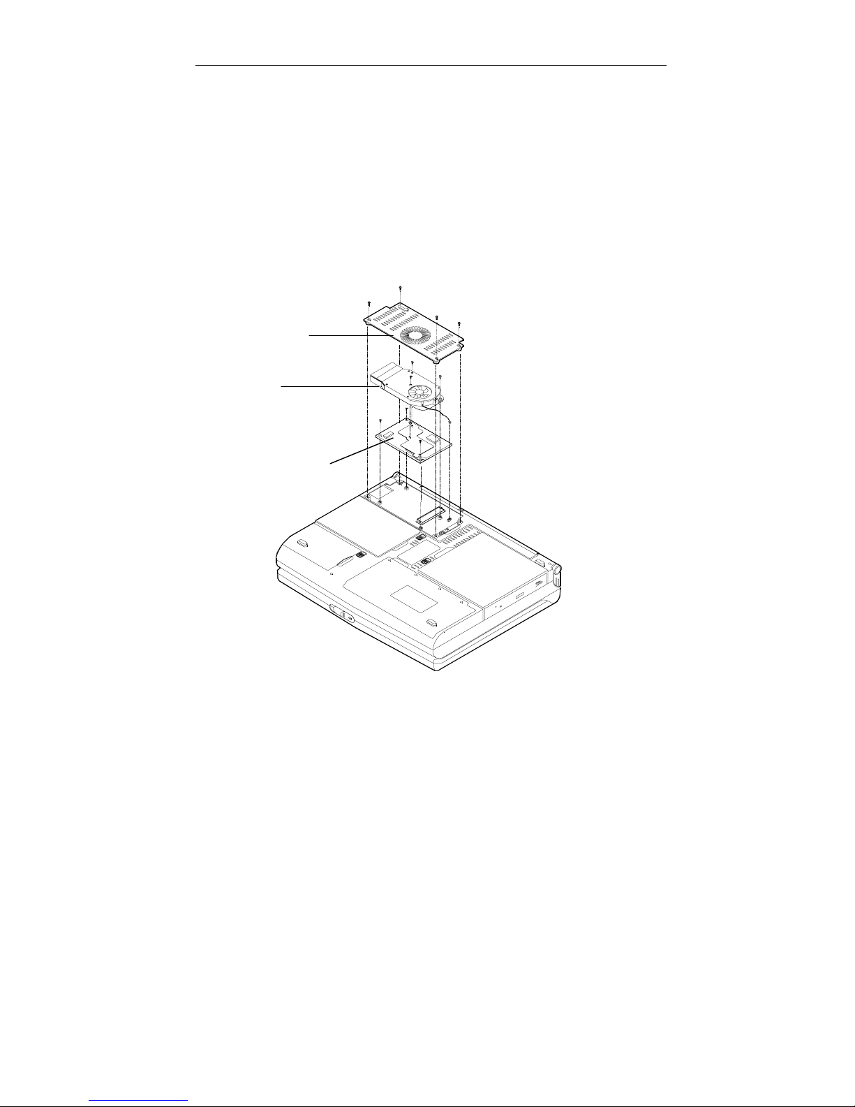
Replacing Processor Module
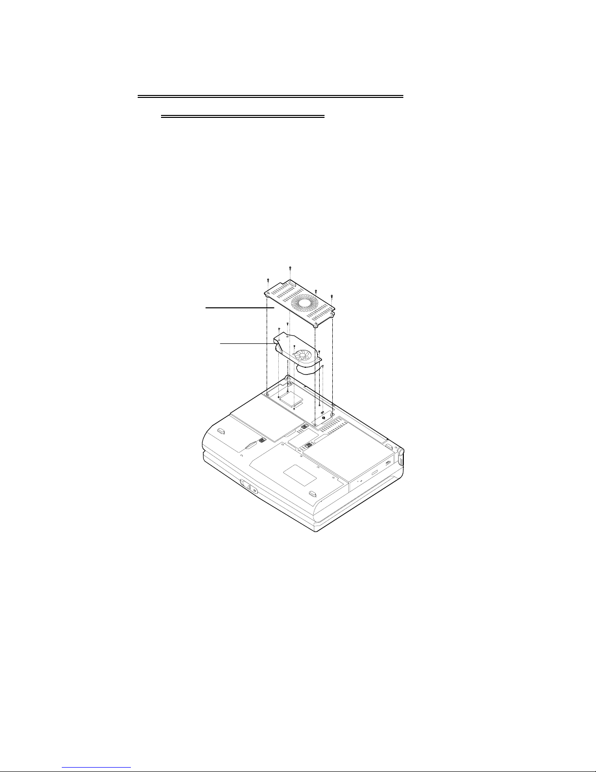
1.
Remove all power sources (AC power and battery).
2.
Turn the computer over.
3.
Remove the CPU cover.
4.
Remove the screws that fasten the heat sink mounted on the
Processor Module.
5.
Carefully detach the Process or Module from the mainboard (F igure 2-
2).
CPU Cover
Heat Sink and Fan
Processor Module
Figure 2-2
Page 32
Upgrading Processor Module
!!!!
on DeskNote 8500C
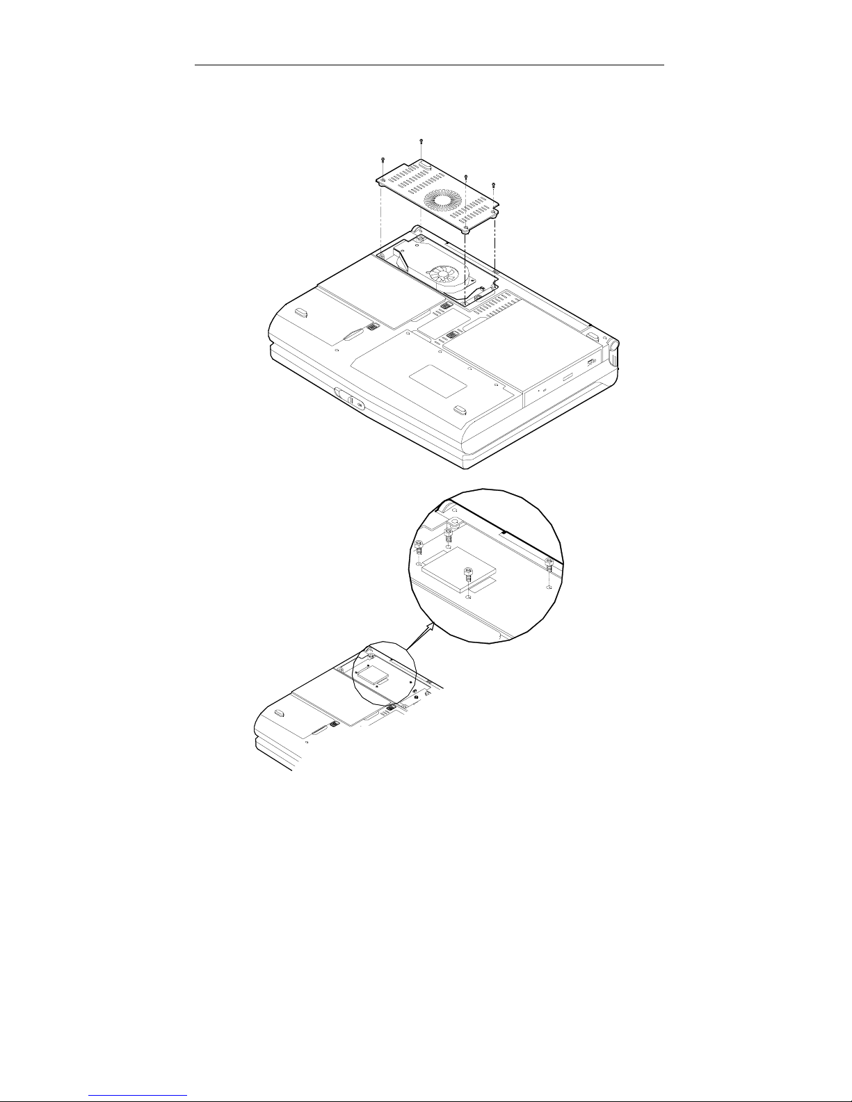
Replacing Processor Module
6.
Remove all power sources (AC power and battery).
7.
Turn the computer over.
8.
Remove the CPU cover.
9.
Remove the screws that fasten the heat sink mounted on the
Processor Module.
10.
Carefully detach the Process or Module from the mainboard (F igure 2-
1).
Heat Sink
and Fan
Figure 2-1.1
Page 33
Chapter 3: BIOS Utilities 2-21
CPU Cover
Figure 2-1.2
Figure 2-1.3
Page 34
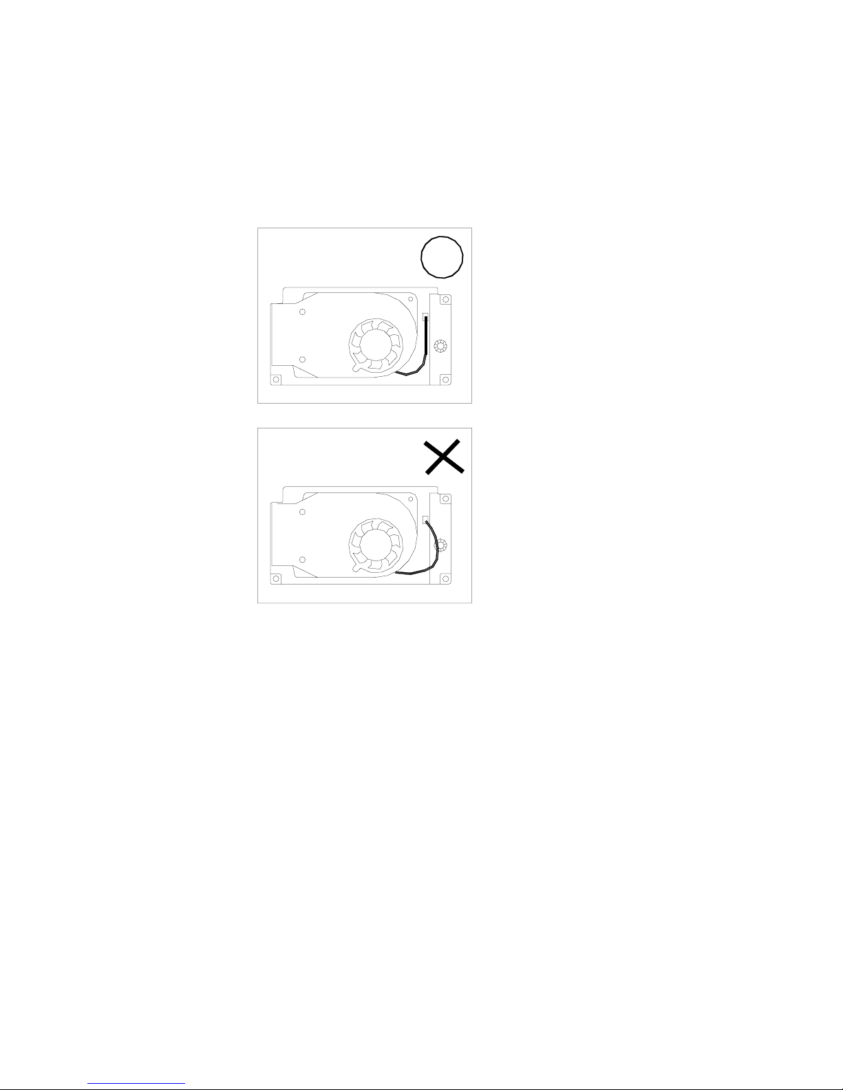
Reinstalling Heat Sink
Reinstall the CPU in the r everse ord er of rem oval. Make sur e that the heat
sink cable is properly installed. (Figure 2-2)
Figure 2-2
Page 35
Chapter 3: BIOS Utilities 2-23
Setting DIP Switch
!!!!
Remove the keyboard to reveal the system’s mainboard. Locate the
DIPSwitch (SW1) to set the correct configuration for the following purpose:
Flash ROM BIOS update
To upgrade your computer, you need to keep up with the latest system
BIOS. Consult your de al er for further inform ation. T he DIP S witc h n eeds t o
be set in the On position when updating th e existing system BIOS. The
DIP Switches should be reset to the Off position after BIOS updating is
complete.
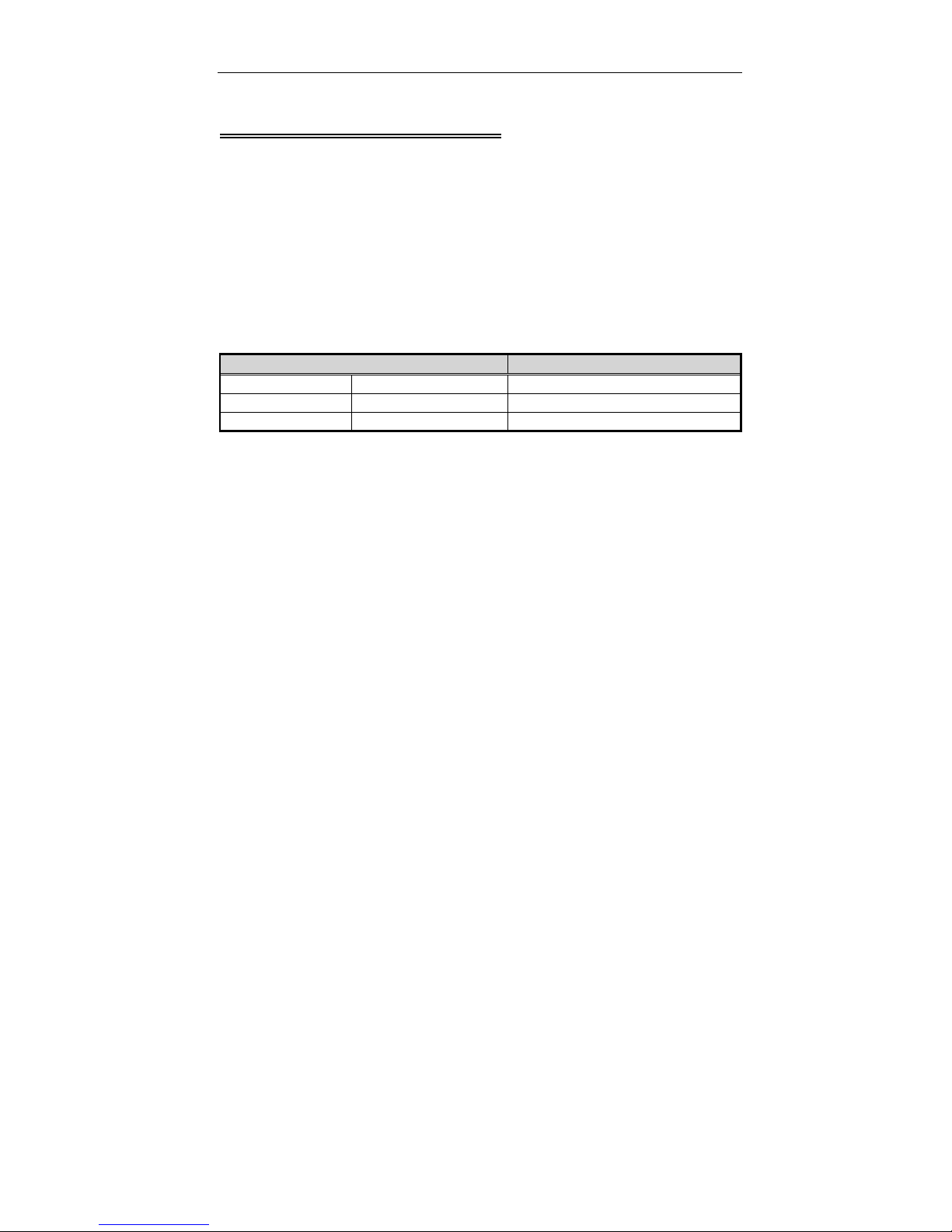
DIP Switch (SW1) Purpose
SW1-1 SW1-2 Flash ROM BIOS
Off Off Existing BIOS
On On Updating BIOS
Accessing DIP Switch (SW1)
1.
Turn the system power off.
2.
Press the two keyboard latches to elevat e the k e yboard fr om its norm al
position (Figure 2-3).
3.
Carefully lift the keyboard assembly out to expose the mainboard.
Locate the DIPSwitch SW1 to set the configuration (Figure 2-4).
Page 36
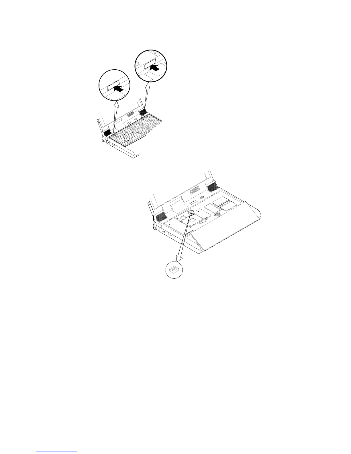
Figure 2-3
SW1
Figure 2-4
Page 37
Chapter 3: BIOS Utilities 2-25
Expanding Memory
!!!!
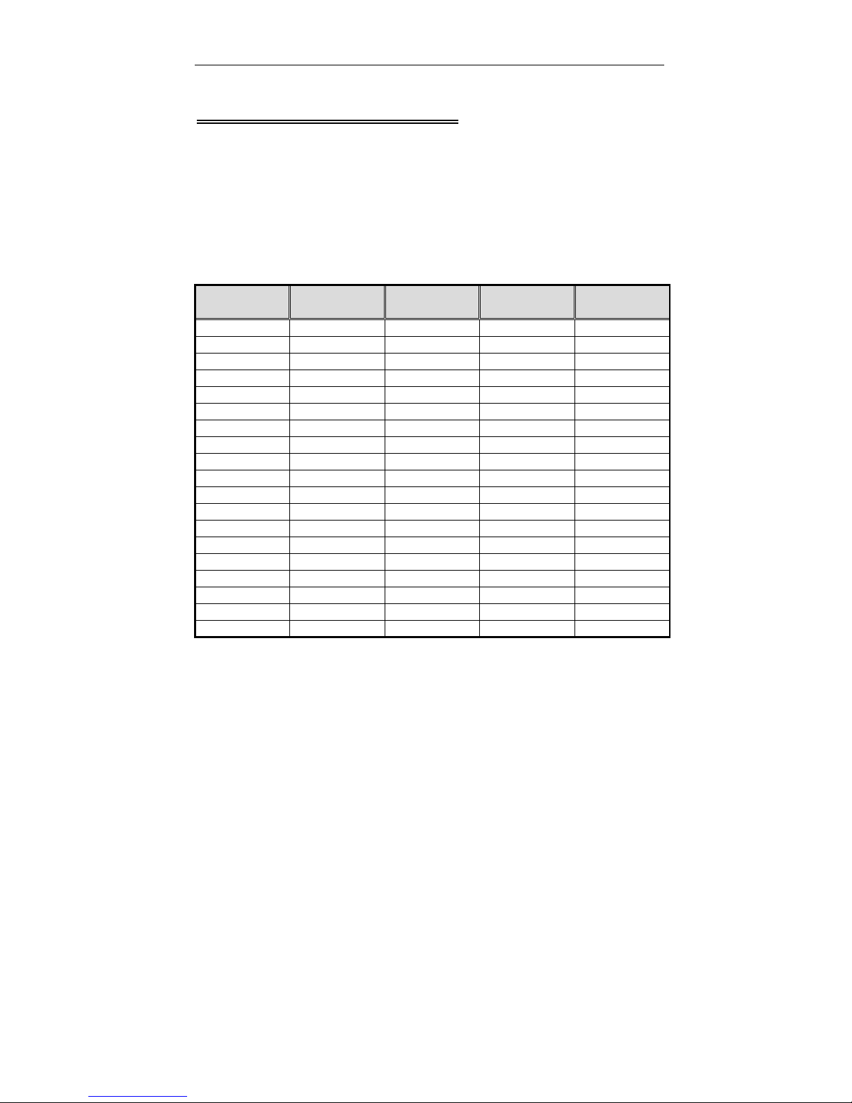
The EUROCOM 8500P/C DeskNote has three memory sock ets for different
RAM modules to expan d the memory up to 384 MB * EUROCOM 85 00P3
DeskNote has two mem ory sockets for up to 256MB of RAM. T he RAM
modules should be 144-pin SODIMM (Small Outline Dual In-line Memory
Module) type. The com puter supports EDO, and SDRAM op eration. The
total memory size is automatically detected by the POST routines. To
expend the memory, you have the following choice with different DRAM
combinations:
Bank 0 Bank 1 Bank 2 * Total Size P3 Total Size
C/P2
32 0 0 32 32
32 32 0 64 64
32 32 32 N/A 96
64 0 0 64 64
64 32 0 96 96
64 32 32 N/A 128
64 64 0 128 128
64 64 32 N/A 160
64 64 64 N/A 192
128 0 0 128 128
128 32 0 160 160
128 32 32 N/A 192
128 64 0 192 192
128 64 32 N/A 224
128 64 64 N/A 256
128 128 0 256 256
128 128 32 N/A 288
128 128 64 N/A 320
128 128 128 N/A 384
Note: * Bank 2 m ight or might not be available on your s ystem, Pent ium III
based systems are equipped with 2 memory sockets only.
Page 38
Accessing the Memory Sockets
1.
Turn the system power off.
2.
Press the two keyboard latches to elevate the keyboard from its
normal position (Figure 2-3).
3.
Carefully lift the keyboard assembly out to expose the mainboard.
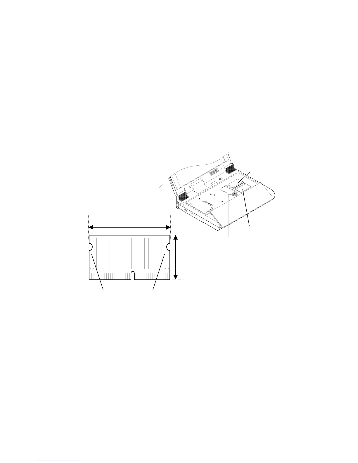
Locate the memory sockets (Figure 2-5).
Note:
The memory socket Bank 1 is a reverse type, make sure you
#
install the memory module with reverse side to fit its connector.
Please ensure that each edge of the memory module (SDRAM)
#
has no component mounted on (see Figure 2-5.1). It is
recommended to use the RAM module that complies with Intel
unbuffered SO-DIMM (67.6mmX31.75mm). Please consult your
dealer for detailed information.
Bank 2
67.6mm
Non-component area
(The edges of the memory module
are the non-component area.)
Figure 2-5.1
31.75mm
Bank 1
Bank 0
Figure 2-5
Page 39
Chapter 3: BIOS Utilities 2-27
Installing Memory Module
Follow the steps below to install the memory module:
1.
Turn the system power off.
2.
Press the two keyboard latches to elevate the keyboard from its
normal position (Figure 2-3).
3.
Carefully lift the keyboard assembly out to expose the mainboard.
Locate the memory sockets (Figure 2-5).
4.
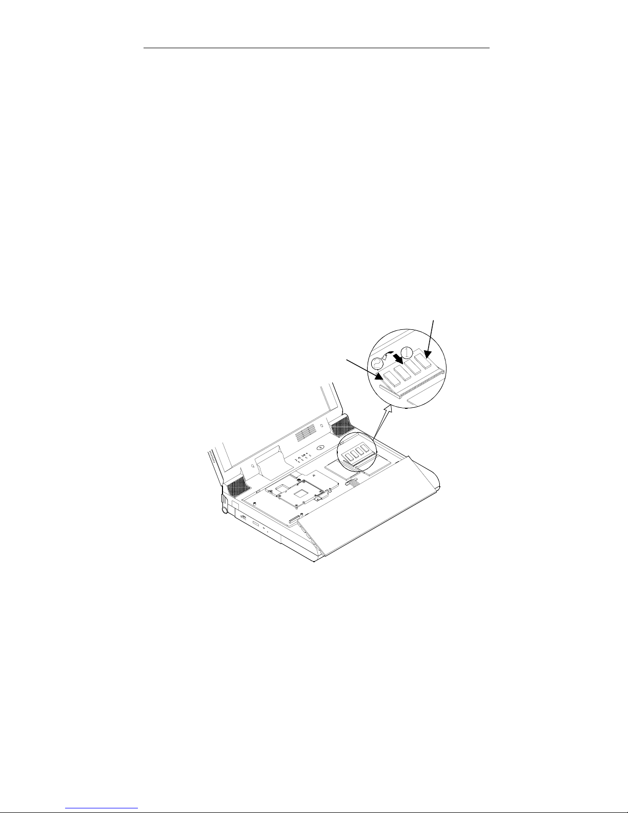
Insert the memory module at a slight angle (45) and fit its
connectors into the socket firmly.
5.
Press two edges of the memory module (as the arrows indicated)
to make it locked into place (Figure 2-6).
6.
Reinstall the keyboard assembly.
Note:
Make sure you install the memory module in the order of Bank 0, Bank
1, Bank 2 (see Figure 2-5). Please refer to the table of DRAM
combinations or consult your dealer for a proper installation.
Figure 2-6
Page 40
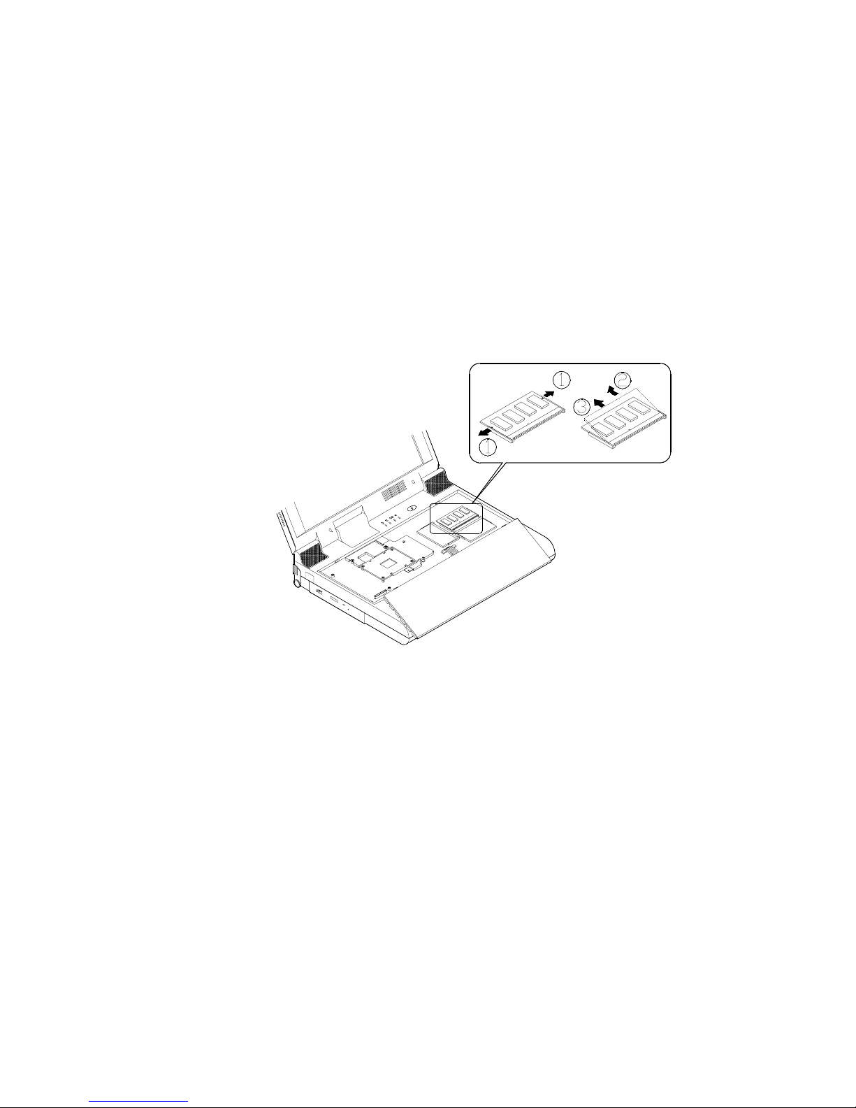
Removing Memory Module
g
1.
Turn the system power off.
2.
Press the two keyboard latches to elevate the keyboard from its
normal position (Figure 2-3).
3.
Carefully lift the keyboard assembly out to expose the mainboard.
Locate the memory sockets (Figure 2-5).
4.
Gently pull the two latc hes outward on bot h ends of the module. The
module will pop up (Figure 2-7).
5.
Remove the memory module.
6.
Reinstall the keyboard assembly.
Fi
ure 2-7
Page 41
Chapter 3: BIOS Utilities 2-29
Using Hard Disk Drive
!!!!
The hard disk drive is mounted in a r emovable case and can be taken out
to accommodate other 2.5” IDE hard dis k drives with a height of 12.7mm.
The system supports drives with 2.0 GB capacities through the Logical
Block Addressing (LBA) mode. It also supports Programmed I/O (PIO)
mode 4, Bus Master IDE and provides a high performance data transfer
rate at speeds up to 33 Mbytes/second (ATA-33).
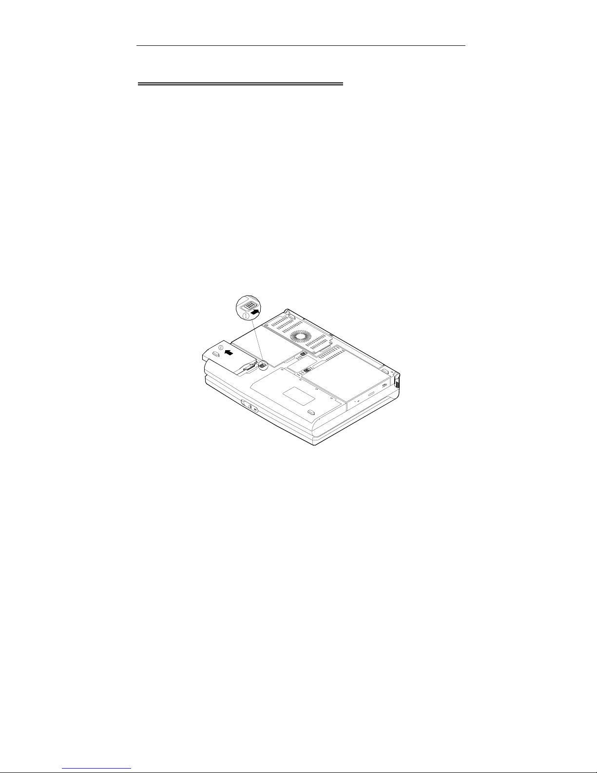
Removing
1.
Turn the system power off.
2.
Turn the computer over.
3.
Locate the Hard Disk Drive latch.
4.
Press the latch in the direction indic ated and take the hard disk drive
out of the computer (Figure 2-8).
Figure 2-8
Note:
When inserting the h ard disk dr ive, insert it firmly int o the com puter. Make
sure you feel the drive click into the position when it is seated properly.
Page 42
Replacing Hard Disk Drive
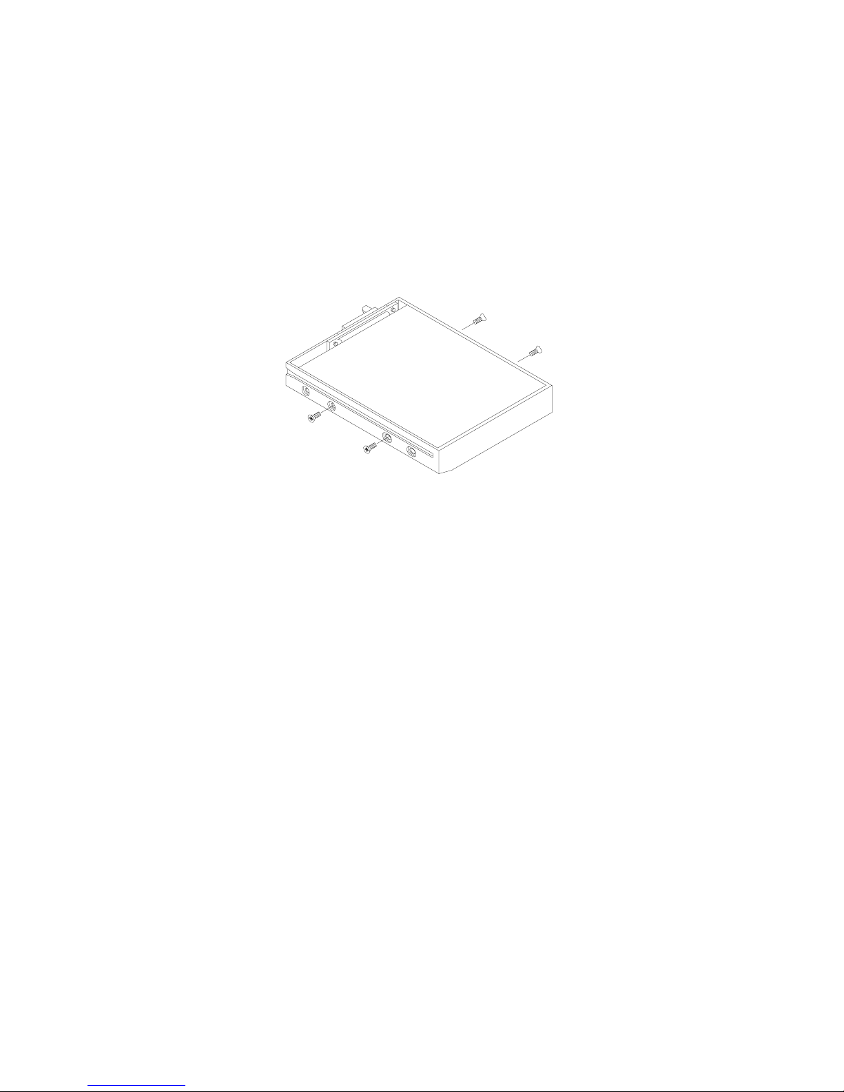
The hard disk drive is contained in a cas e. To take the hard disk drive out
of the case and replace with another one, you need to remove the two
screws on each side of the case (Figure 2-9). The location of the two
screws may be varied depending on different types of hard disk model.
Gently disconnect the cable from the hard disk drive when taking it out of
the case. Be careful not to bend any pins or crimp the cable.
Figure 2-9
Page 43
Chapter 3: BIOS Utilities 2-31
Using Floppy Disk Drive
!!!!
The DeskNote computer comes standard with a 1.44MB, 3.5” flopp y disk
drive module. It is labeled dr ive A: and may be used as a boot device if
properly set.
You may replace the flop py disk module with the foll owing options: a 2.5”
secondary hard disk drive (of 12.7mm or 17mm high), a 3.0” secondary
hard disk drive (of 12.5mm high), a 100M B Zip drive (of 15mm high), or a
LS-120 device (of 12.7mm high). Contact your dealer for details about
these options.
Inserting/Removing Diskettes
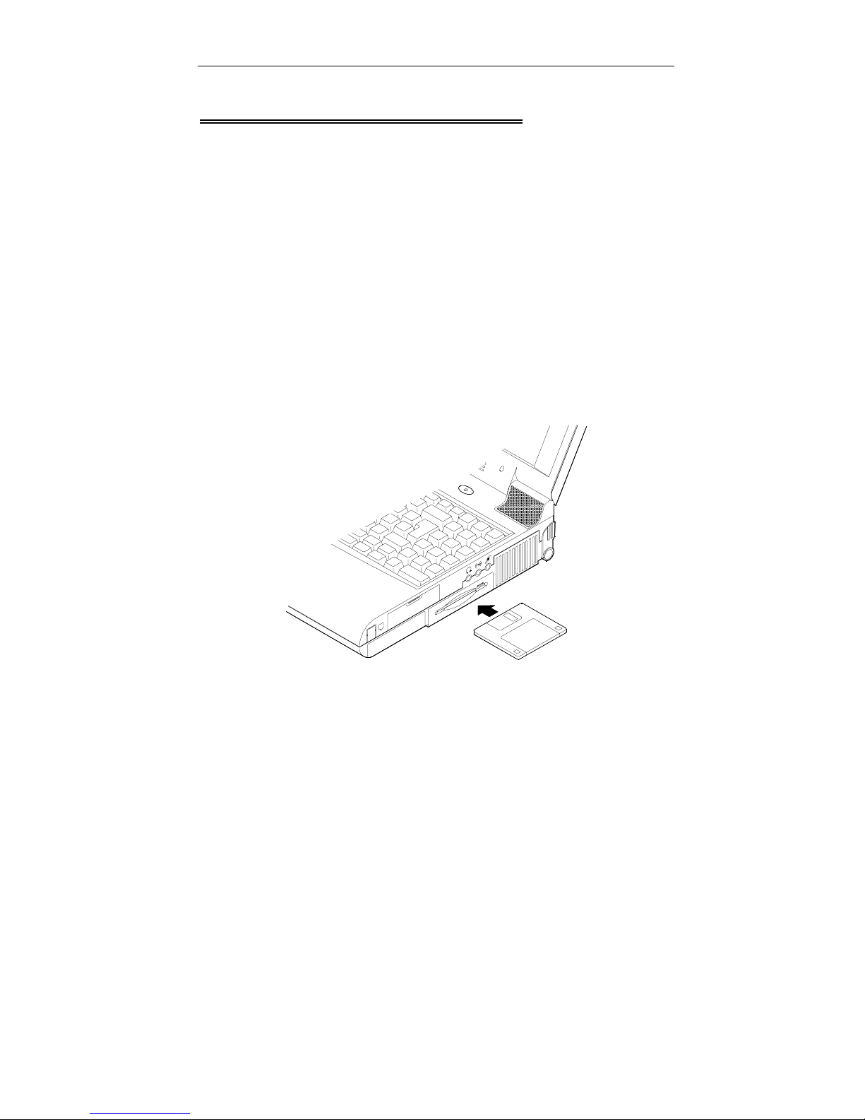
When using the flop py drive, always insert your flopp y diskette labe l-side
up (Figure 2-10). To remove your disk ette, press the eject button on the
top-right corner of the floppy drive.
Figure 2-10
Page 44
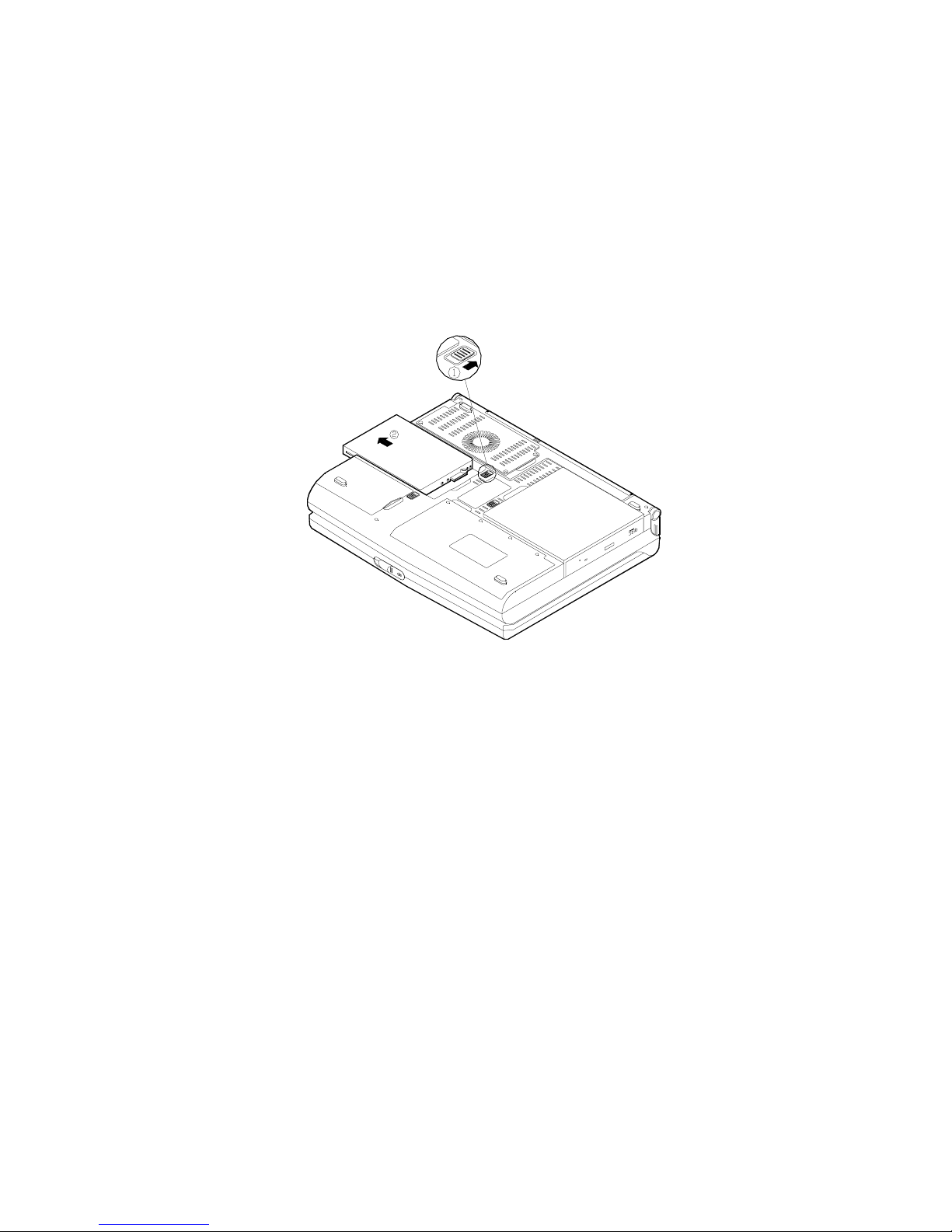
Replacing Floppy Disk Drive
1.
Turn the system power off.
2.
Turn the computer over.
3.
Locate the Floppy Disk Drive latch.
4.
Press the latch in the direct ion indic ated and take the f lopp y disk dr ive
out of the computer (Figure 2-11).
5.
Insert the replacement dri ve (2.5”/3.0” secondary HDD or 100 MB Zip
drive) firmly into the computer.
Figure 2-11
Page 45
Chapter 3: BIOS Utilities 2-33
Using CD-ROM
!!!!
The EUROCOM DeskNote computer comes standard with a removable
5.25” CD-ROM module. It is labeled drive D: an d may be used as a boot
device if properly set.
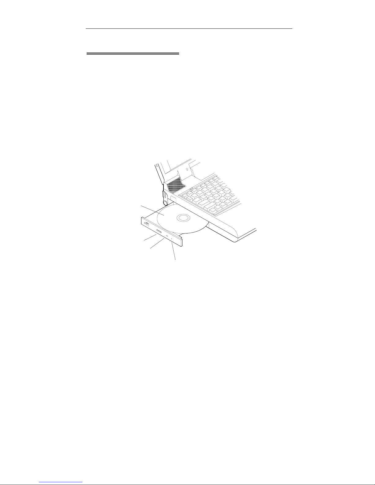
To insert a CD, press the Eject Button and place the CD into the Disc
Tray with l abel-side facing up. Push the CD tray in and you are ready to
start. The Busy Indicator will light up while data is being accessed or
while an audio CD is pla ying. W hen the power is unex pecte dly inter rupted ,
insert an instrument suc h as a straight ened paper cl ip into the Emergency
Eject Hole to eject the tray (Figure 2-12).
Disc Tray
Eject Button
Busy Indicator
Emergency Eject
Figure 2-12
Page 46
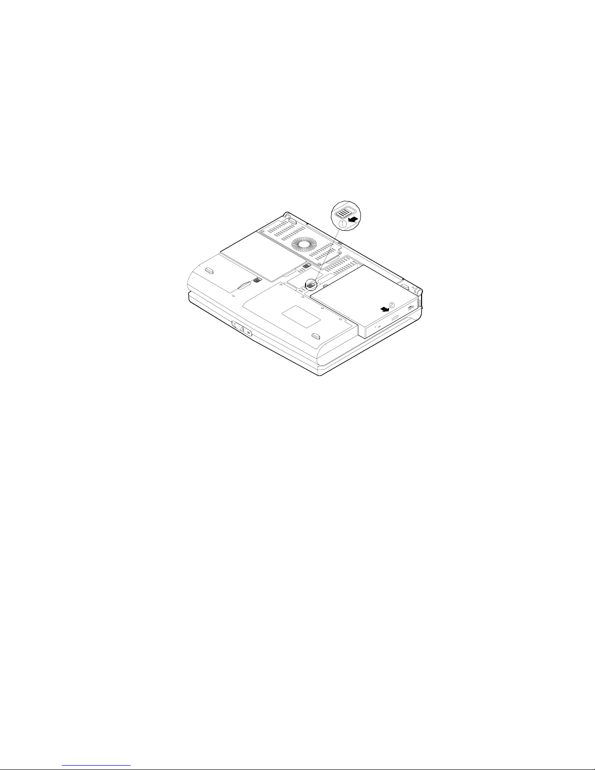
Removing CD-ROM Module
1.
Turn the system power off.
2.
Turn the computer over.
3.
Locate the CD-ROM latch.
4.
Press the latch in the direction indicated and take the CD-ROM
module out of the computer (Figure 2-13).
Figure 2-13
Page 47
Chapter 3: BIOS Utilities 2-35
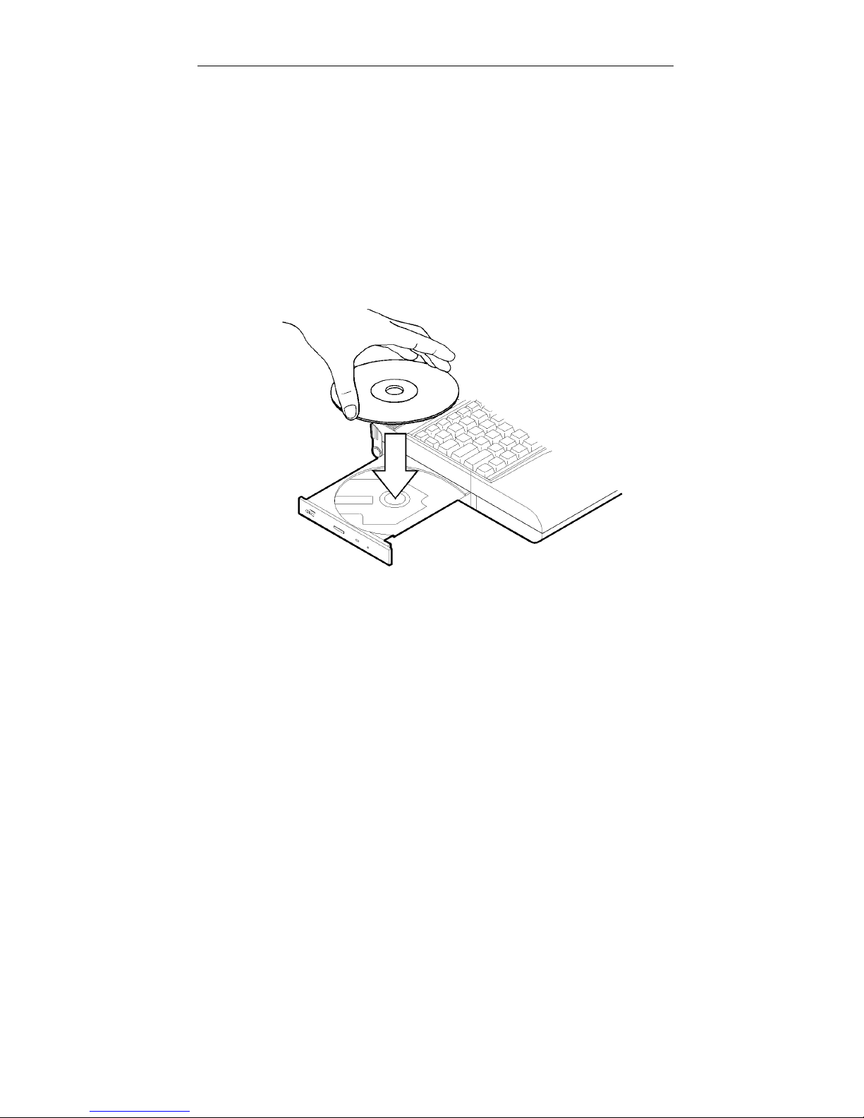
Loading Compact Discs
1.
Turn on the power.
2.
Press the CD-ROM eject button; the disc tray will pop out partially.
3.
Pull the disc tray out.
4.
Carefully load the CD into the disc tray with label-side facing up.
Press it gently to ensure it fits into the place (Figure 2-14).
5.
Push the tray into the computer.
Figure 2-14
Page 48

Handling of Compact Discs
Proper handling of your CDs will prevent them from being damaged and
ensure the accessibility of data stored in them.
Hold the CD by the edges; do not touch the surface of the disc.
$
Use clean, soft, and dry cloth to remove dust or fingerprints.
$
Do not use pen to wr ite on the surf ac e.
$
Do not attach any paper or other materials to the surface of the disk.
$
Do not store or place the CD in the high-temperature areas.
$
Do not use benzene, thinners, or other cleaners to clean the CD.
$
Do not bend the compact disc.
$
Do not drop or subject the CDs to shock.
$
Page 49
Chapter 3: BIOS Utilities 2-37
Using PC Card Sockets
!!!!
The computer provides system expansion capabilities with two PC card
sockets (previously referred to as PCMCIA). PC cards to be inserted can
be LAN, fax/modem , communication devices, or ex panded memory. Both
sockets support 5V/3.3V 16-bit PC cards and 3.3V 32-bit PC cards
(referred to as CardBus).
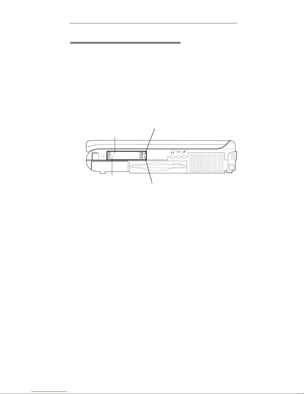
The PC card sockets on the right-side panel support one Type III card
(equivalent to t wo Type II cards). The lower sock et (s ocket A) is c apab le of
ZV (Zoomed Video) (Figure 2-15).
Eject button for socket B
Socket B
Socket A
Eject button for socket A
Note:
There are three types o f PC cards. Type 1 measures 3.3 m m thick;
T ype II 5.0 mm; and Type III 10.5 mm.
Figure 2-15
Page 50
Inserting PC Cards
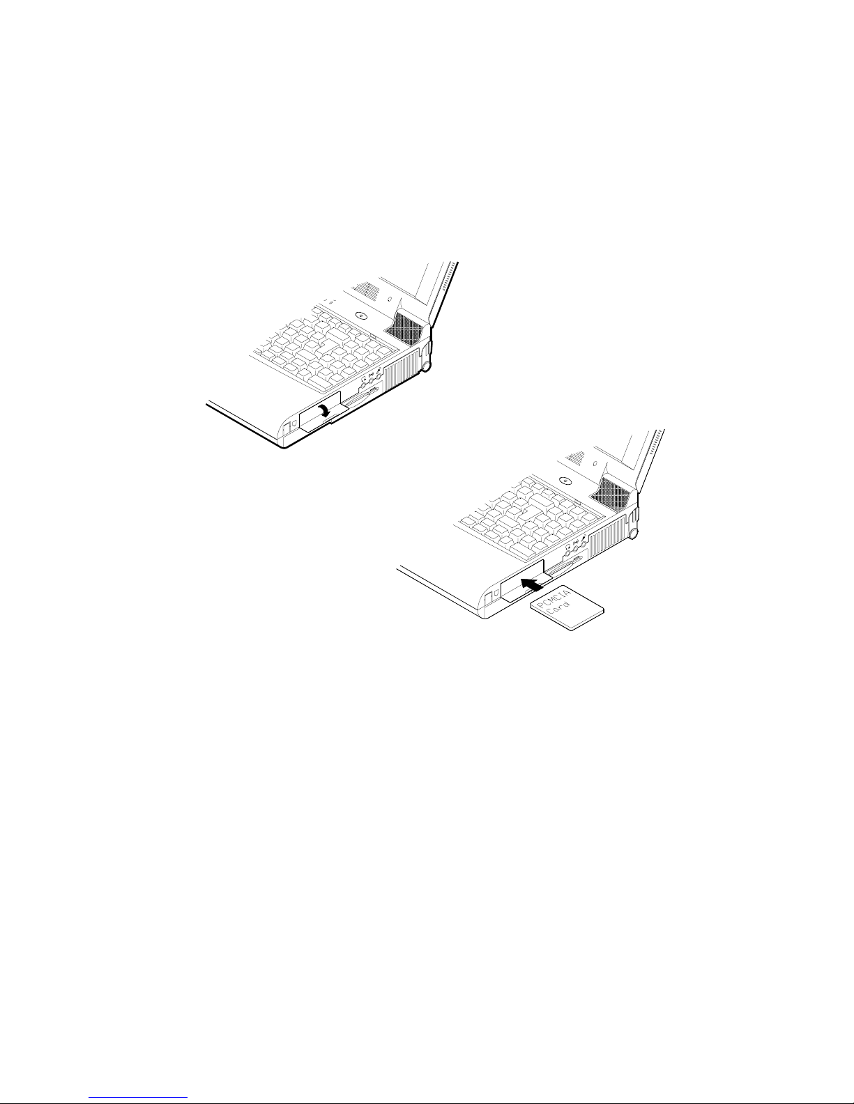
1. Open the access door (Figure 2-16).
2.
Align the PC card with the slot and push it i n f irmly until it lock s into the
place (Figure 2-17).
.
Figure 2-16
Figure 2-17
Removing PC Cards
To remove a PC card, press the appro priate eject button to eject th e card
from its slot. (Figure 2-15).
Page 51
Chapter 3: BIOS Utilities 2-39
Using Hot Keys
!!!!
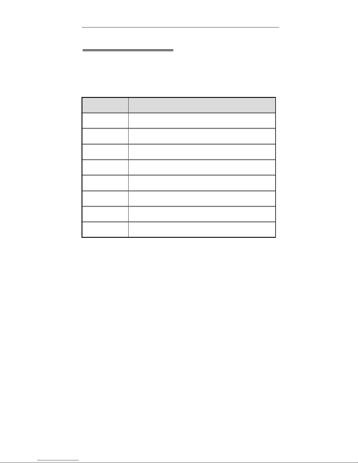
Located on the bottom -lef t edge of th e k eyboard l ayout is a co lored Fn key.
The Fn key function allows you to change operational features instantly.
When you use the following functions, press and hold the Fn key; then
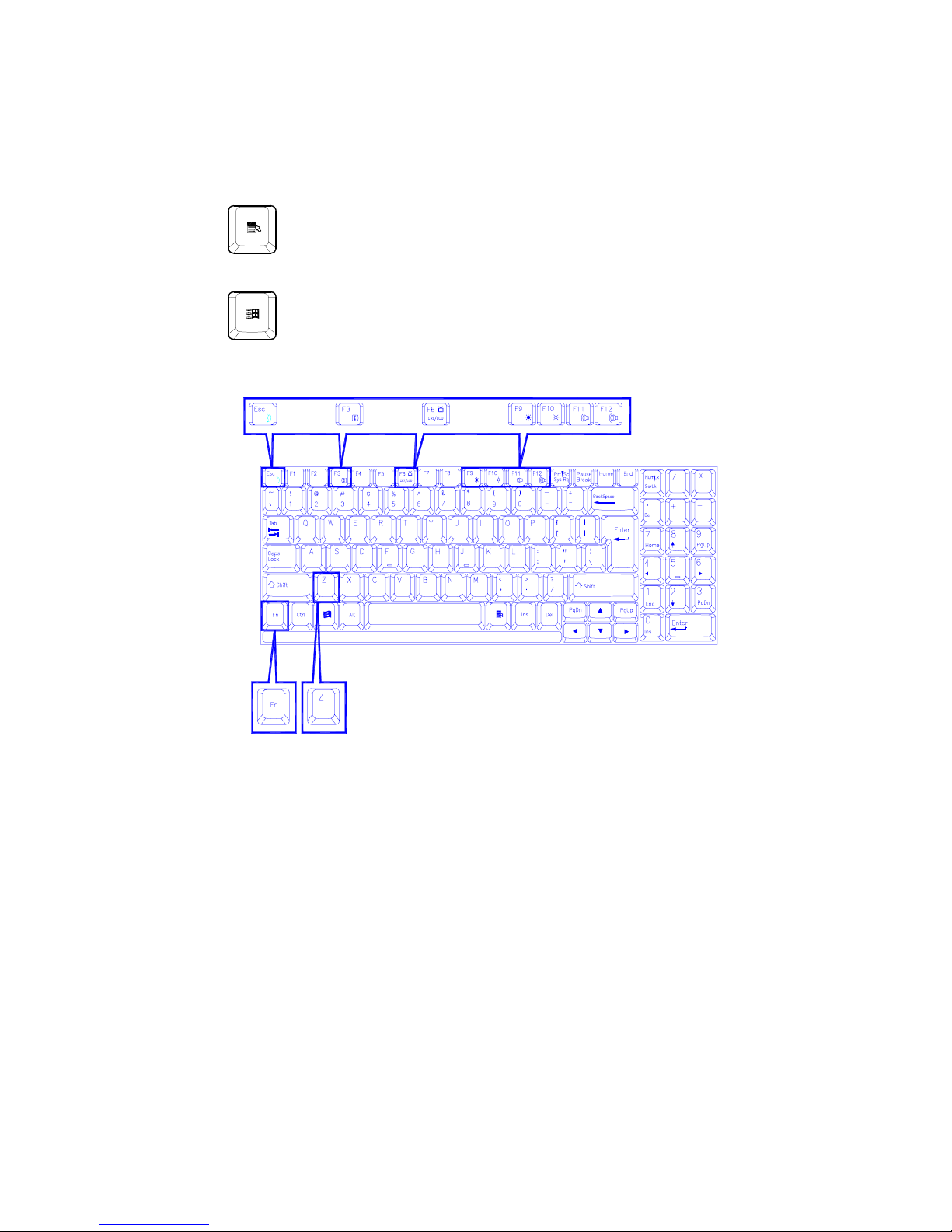
press the appropriate function key (Figure 2-18).
Hot Keys System Features
Fn + F3
Fn + F6
Fn + F9
Fn + F10
Fn + F11
Fn + F12
Fn + Z
Fn + Esc
Expand LCD display.
Toggle CRT/LCD/LCD+CRT/TV/CRT+TV.
Decrease LCD brightness.
Increase LCD brightness.
Decrease audio volume.
Increase audio volume.
Turn audio mute on/off.
Put the system in a suspend state for power
management.
Page 52
Windows 95 Special Keys
The keyboard provides two keys that have special functions in Windows
95:
This key has the same functions as the secondary mouse does.
This key activates the Windows 95 Start menu.
Figure 2-18
Page 53
Chapter 3: BIOS Utilities 2-41
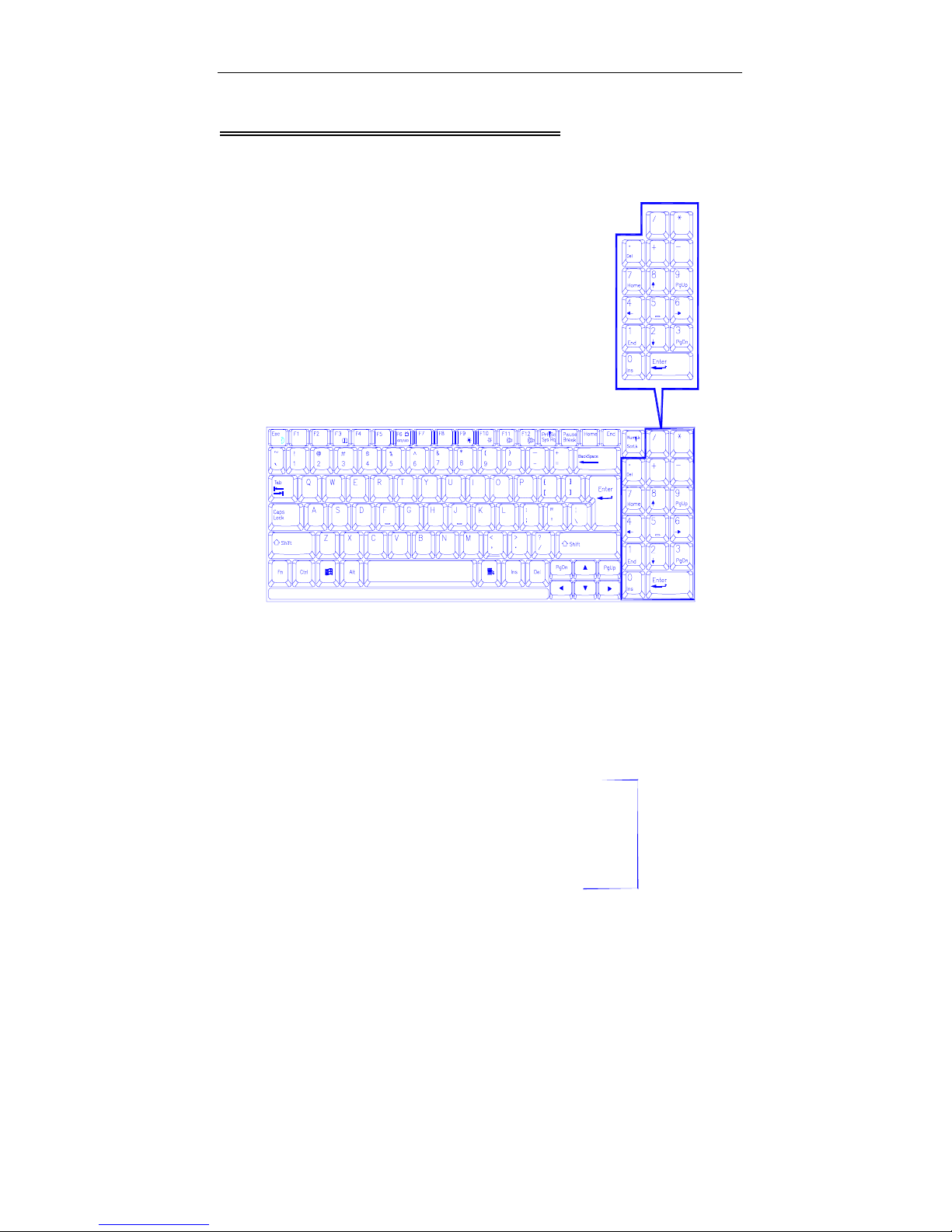
Using Numeric Keypad
!!!!
The computer features a 102-key keyboard with an integrated numeric
keypad for easy numeric data input (Figure 2-19).
Figure 2-19
Page 54

Using Power Management
!!!!
The system provides you with various modes to manage its power
consumption while maintaining system performance. Please refer to
Chapter 3: BIOS Utilities, System Configuration Utility, Power Menu for
more information.
Advanced Power Management (APM 1.2)
The system provides built-in Advanced Power Management (APM 1.2)
support to reduce power consumption . APM function var ies depending on
the operation system you are using. Some operation systems do not
support APM, such as Windows NT, and therefore, cannot take
advantage of the system’s capabilities in this area.
Global Standby
In Global Standby mode, the CPU clock will be stopped and most
controllable peripheral devices will be power off. If the idle timer expires
before any system activity is detected, the system will change from
Standby mode into Suspend mode.
Hard Disk Standby
The system will turn off the c omputer’s hard disk drive m otor if it has not
been accessed after a specified peri od of time. The motor will be tur ned
back on if the system attempts to read or write data to it.
Page 55

Chapter 3: BIOS Utilities 2-43
Suspend and Resume
When at extremely low power, you can enter suspend mode to s av e power.
In suspend mode, all tasks are stopped and stored in memory to save
power. The system features two levels of suspend mode: Powered-OnSuspend (POS) mode and Suspend-To-Disk (STD) mode.
Another useful feature is resum e mode. This f eature allo ws you t o turn the
computer ’s power off without exiting your soft ware application. W hen you
turn the power on again, you can resum e work where you l eft off, bec ause
the screen
power.
display is restor ed as you left it. This saves time and batter y
Caution:
1. Accessing any of the disk drives, such as HDD, FDD or CD-ROM drives.
2. Using the audio features or playing back video.
3. Playing a DOS game.
Do not enter suspend mode when you are
Powered On Suspend (POS)
Of the suspend modes, Powered-On-Suspend saves the least amount of
power. However, it takes the shortest time to return to full operation.
Resume from POS Mode
The system can resume from Powered-On-Suspend mode by:
Alarm resume (month/day/hour/minute)
$
Modem ring
$
Pressing any keyboard key.
$
Pressing the power button (if configured as Suspend/Res ume function
$
under SCU)
Opening the display lid (only if the suspend mode is initiated by closing
$
the display lid)
Page 56

Suspend To Disk (STD)
Suspend to Disk is a 0-vol t suspend m ode for s ystem power m anagement.
STD mode saves the maxim um power but takes the longest time to retur n
to full operation.
1.
Use your operation s ystem’s FDISK program to delete all partitions of
the hard disk if any already exist on the target drive.
2.
Boot the system and run the 0VMAKFIL.EXE Utility to create the
Suspend to Disk partition on the hard disk. The size of Suspend to
Disk partition wil l be the ins tal led DRA M (n) p lus 8MB in tegra ted vide o
RAM.
:\>0VMAKFIL –Pn
For example, if the system DRAM is 32MB, 0VMAKFIL will create a
partition size of approximately 40MB.
:\>0VMAKFIL –P32
Resume from STD Mode
The system will resume from Suspend-To-Disk mode by:
•
Power back on
•
Alarm resume (month/day/hour/minute)
•
Opening the displa y lid (only if the suspe nd mode is initiated b y
closing the display lid)
Page 57
Chapter 3: BIOS Utilities 2-45
Attaching Peripheral Devices
!!!!
To extend the computer ’s functions , you can att ach the f ollowing peripher al
devices to the computer through the ports or jacks on the rear panel of
computer.
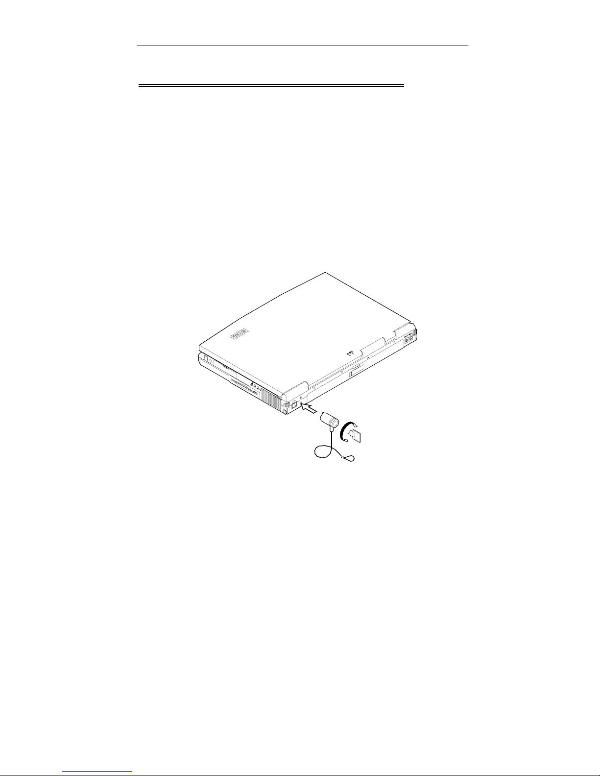
Attaching a Security Lock
The security lock is equipped to protect your com puter from being sto len.
To install the security lock, wrap the cable around a desk or other
immovable object, then inser t the locking de vice into the co nnector (Figure
2-20).
Figure 2-20
Page 58
Attaching a Parallel Printer
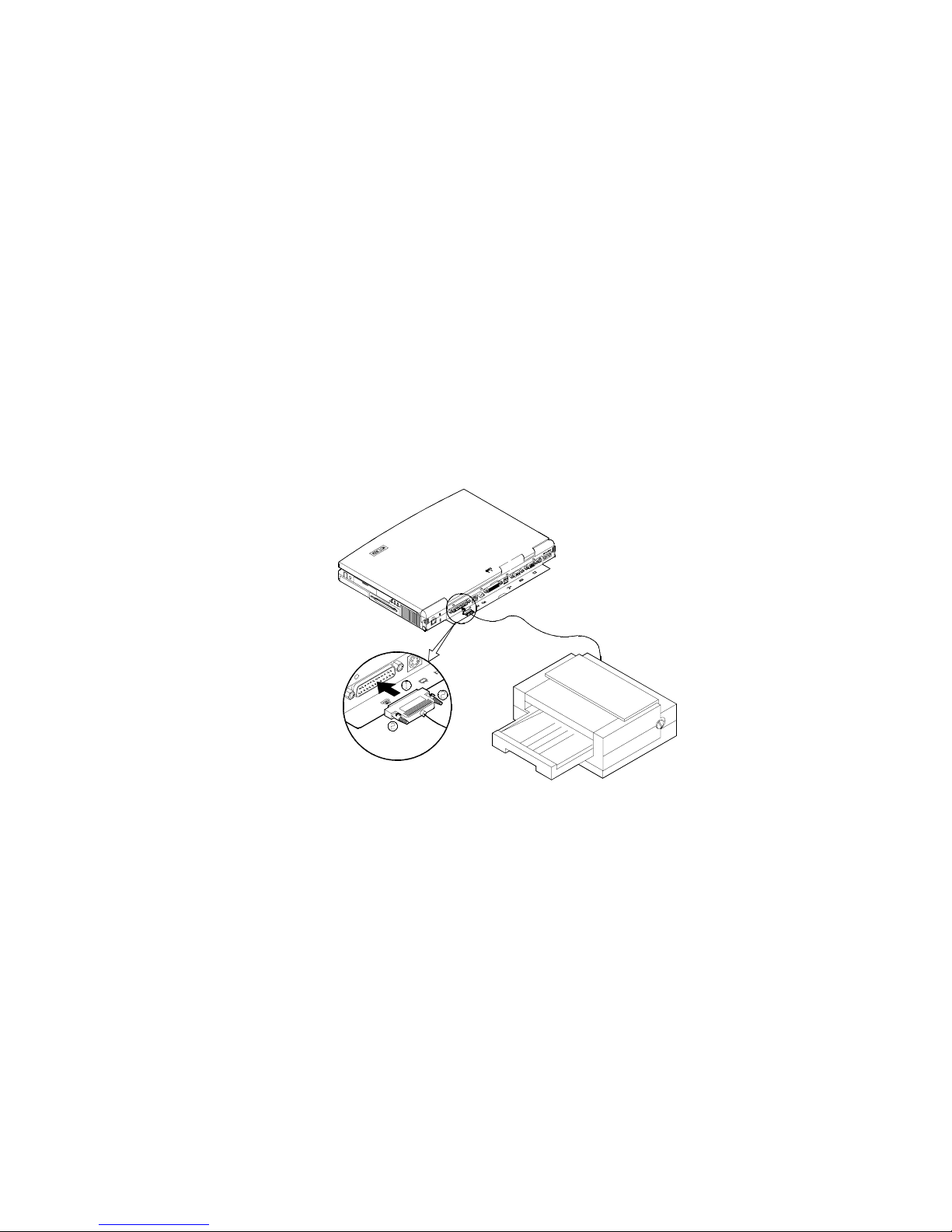
You may connect any standard Centronics paralle l printer t o your com puter
through the parallel port.
1.
Turn the system power off.
2.
Connect the cable to the parallel port on the rear of the computer.
3.
Tighten the screws that fasten th e cable to the par allel port ( Figure 2-
21).
4.
Insert the other end of the cabl e to the pri nter’s connector. Fasten the
cable’s connector.
5.
Turn on the printer and computer.
In addition, you also need to install th e manuf acturer- supplied dr iver for the
printer. Refer to the device’s user’s guide for more information. If the
connected printer supports EPP (Enhanced Parallel Port) or ECP
(Extended Capabilities Port) mode, please enter System Configuration
Utility (SCU) to configure the required setting.
Figure 2-21
Page 59
Chapter 3: BIOS Utilities 2-47
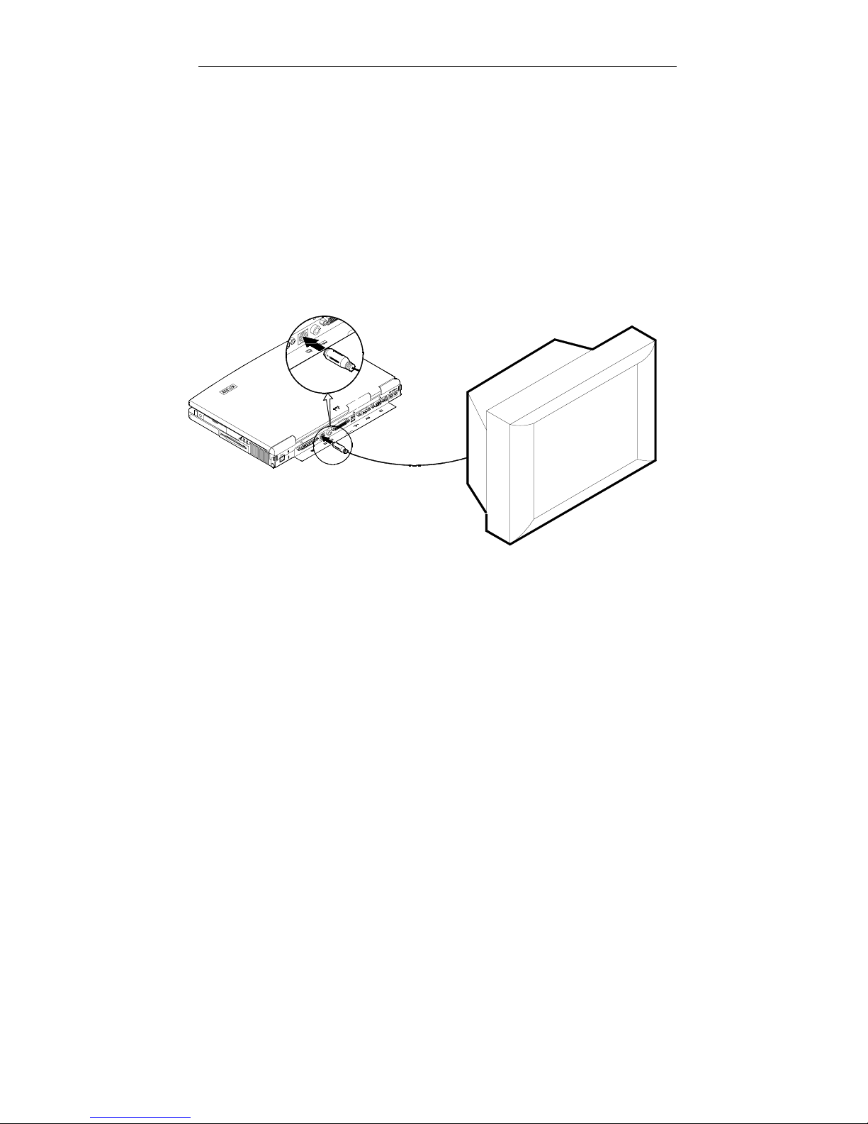
Attaching a TV Set
The S-Video jack on the rear panel of the com puter is use d for trans mitting
video signals to a TV set. You may need to select th e video standard for
video display. Enter the System Configuration Utilit y (SCU), Components
Menu to specify the appropriate TV mode. Simultaneous display on
external monitor (CRT) and TV is available. You can enter the SCU to
select the appropriate parameters or use the Fn + F6 keys (refer to Chapter
2, Using Hot Keys).
Attach the TV set as shown below (Figure 2-22).
Figure 2-22
Page 60
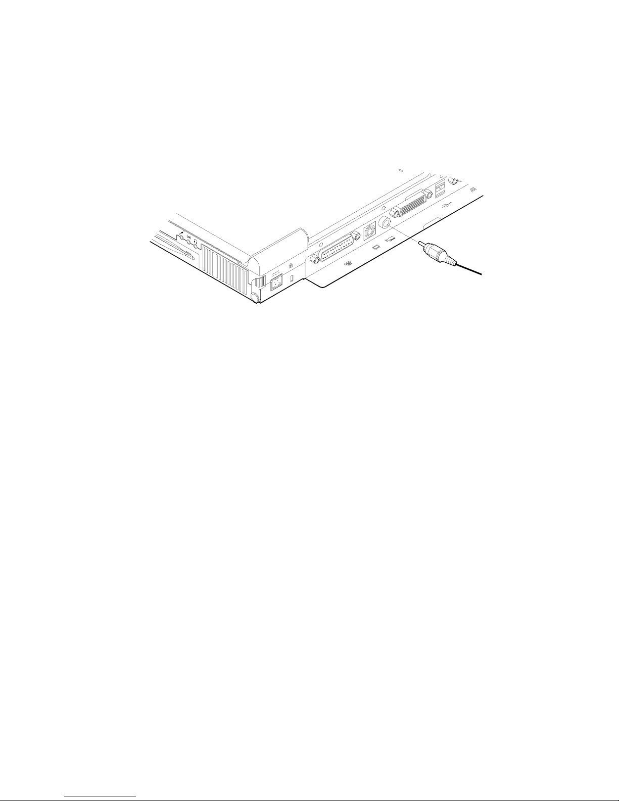
Attaching a Video Input Device
The RCA jack on the re ar panel of the com puter allows an alog composite
signal input from external video devices. Attach the device as shown below
(Figure 2-23).
Figure 2-23
Page 61
Chapter 3: BIOS Utilities 2-49
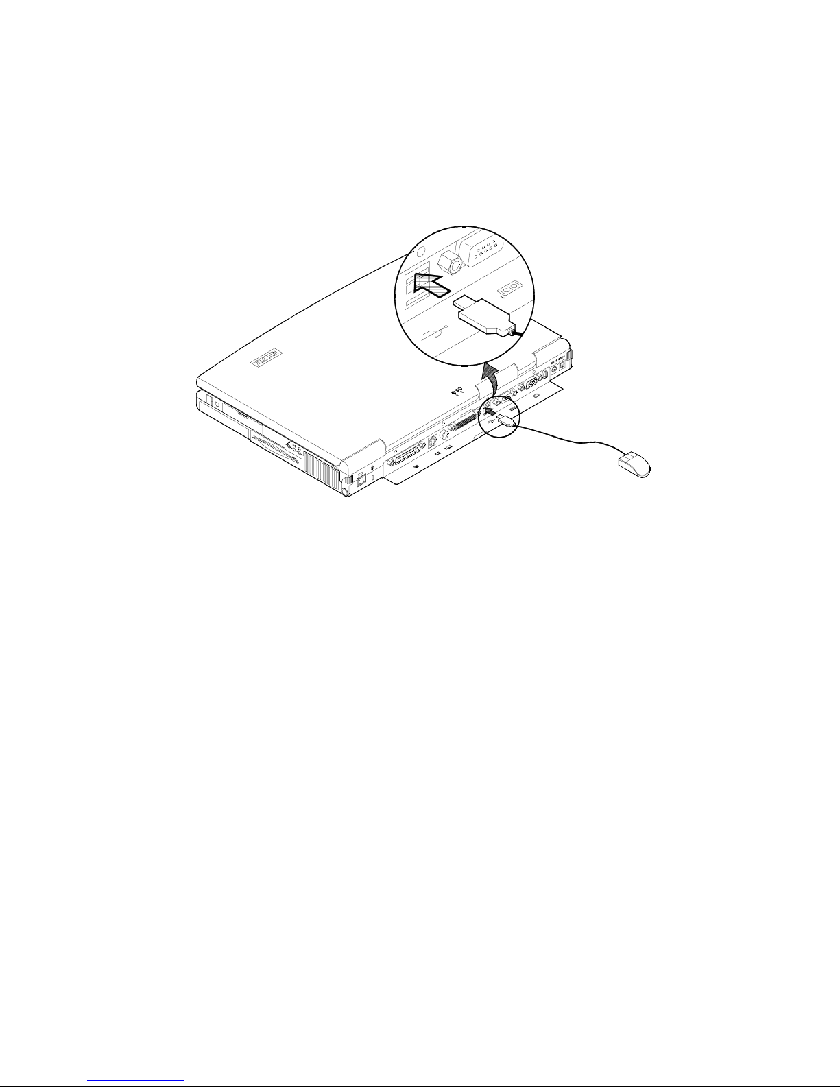
Attaching a USB-compatible Device
The computer provides dual U SB por ts f or conn ectio n of a U SB-c om patible
keyboard, mouse, or other devices. Attach the device as shown below
(Figure 2-24).
Figure 2-24
Page 62
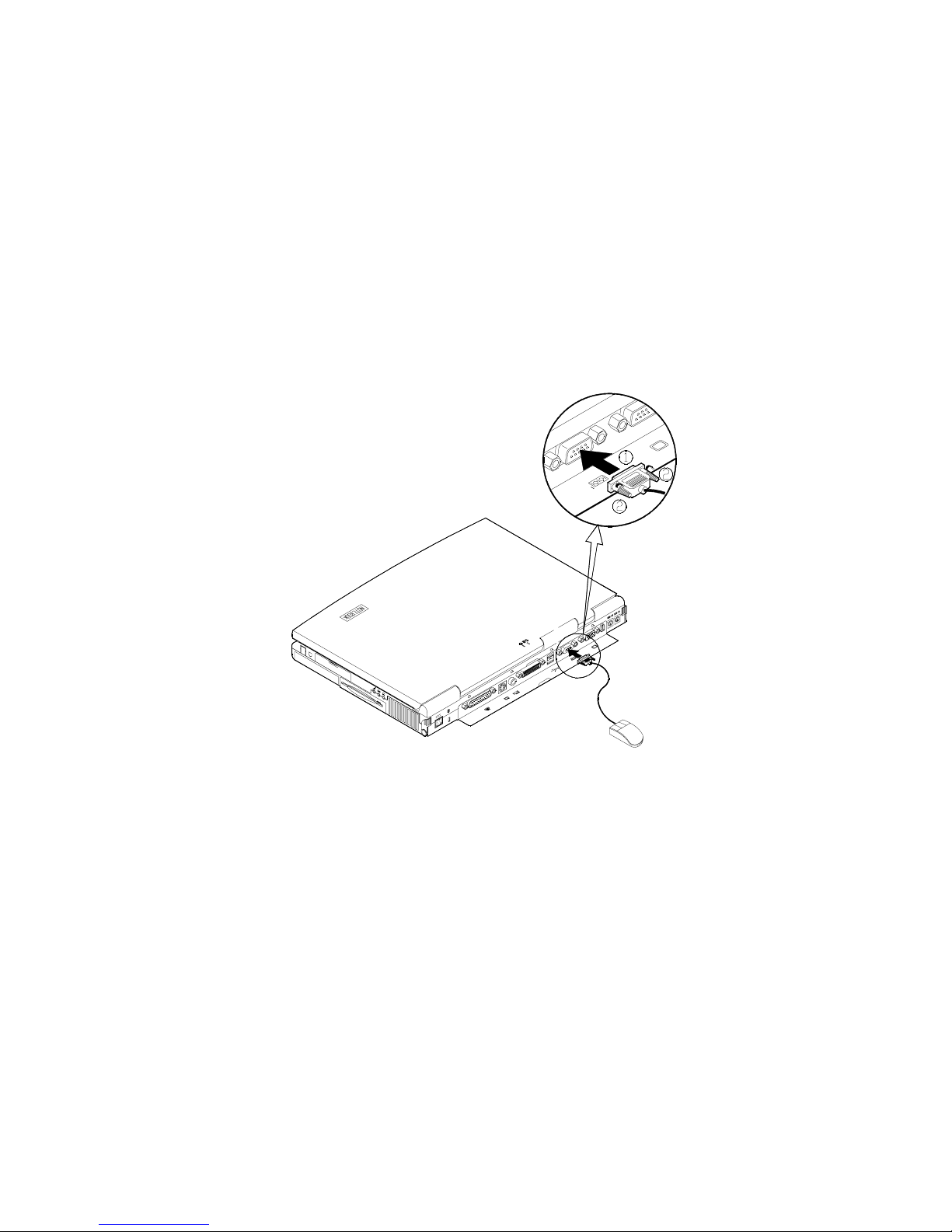
Attaching a Serial Mouse
The serial port features a 9-pin connector. You can connect any serial
device such as a mouse to this port.
1.
Turn the system power off.
2.
Connect the cable to the serial port on the rear of the computer.
3.
Tighten the screws that fasten th e cable to the serial port (Figure 2-
25).
4.
Turn on the computer.
In addition, you m ay need to insta ll the m anuf actur er-s upplied dr iver f or the
serial mouse. Refer to the device’s user’s guide for more information.
Figure 2-25
Page 63
Chapter 3: BIOS Utilities 2-51
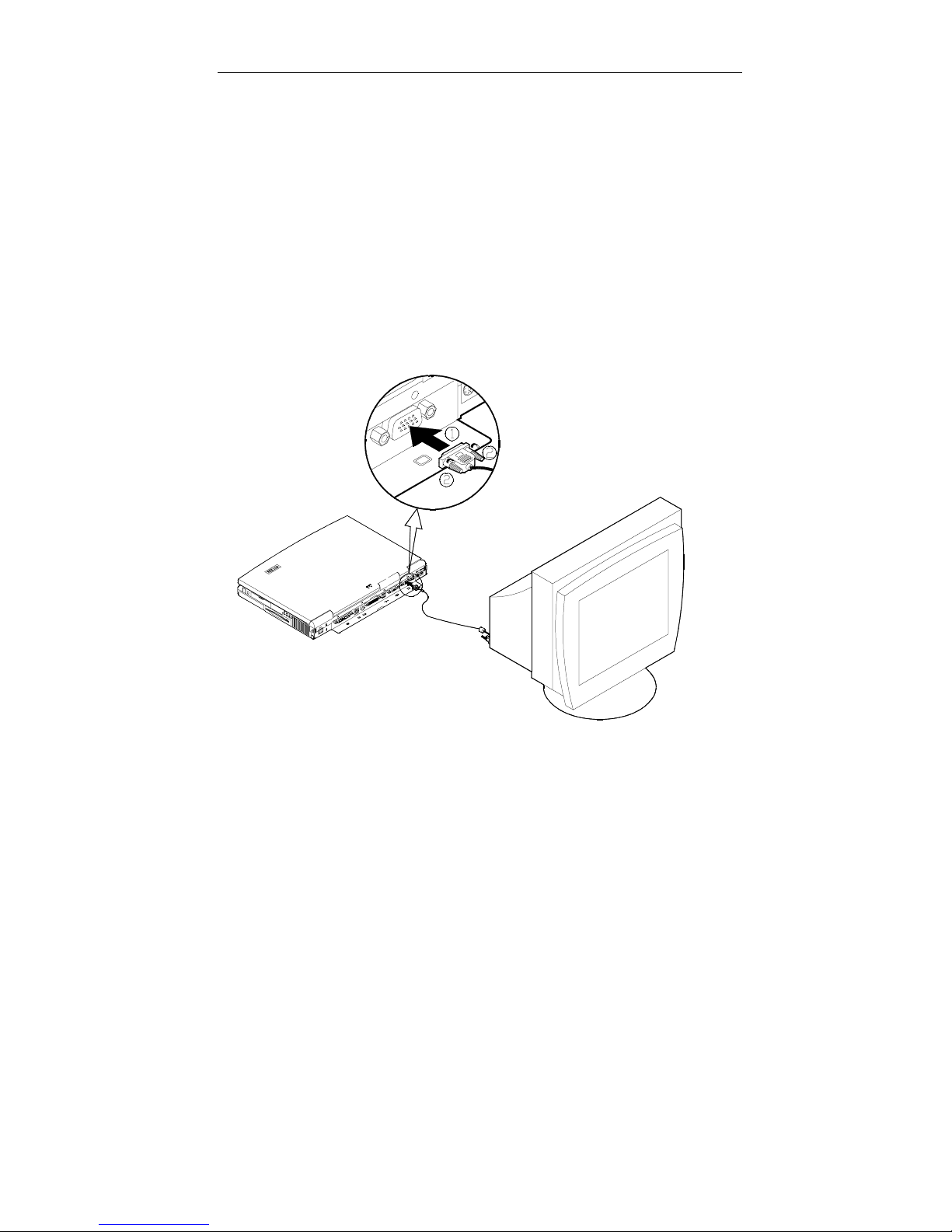
Attaching an External Monitor (CRT)
The computer is capa ble of disp la ying not onl y on t he LC D, b ut a lso on the
XGA compatible displays attached to the computer. Information can be
displayed on both the LCD and the external m onitor simultaneo usly. Enter
the System Configura tio n Ut ili ty (SCU) to select the a ppr opr iat e par ameters
or use the Fn + F6 keys (refer to Chapter 2, Using Hot Keys).
1.
Turn the system power off.
2.
Connect the cable to the CRT port on the rear of the computer.
3.
Tighten the screws that fasten the cable to the CRT port (Figure 2-26).
4.
Insert the other end of the cable to the external monitor.
5.
Turn on the computer.
Figure 2-26
Page 64
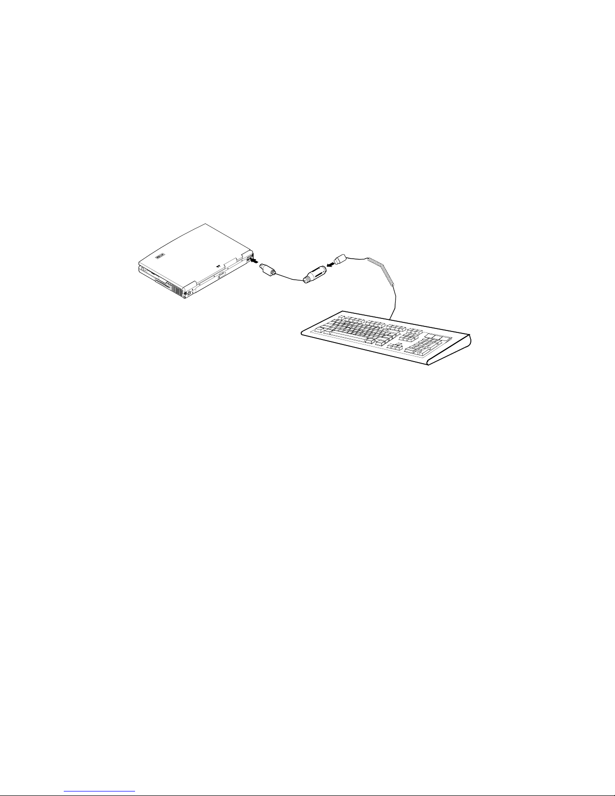
Attaching a PS/2 Keyboard or Mouse
The computer can be op er ate d with a P S/2 keyboard or mouse attac he d by
means of the PS/2 trans fer cable. Attach the external ke yboard or mouse
as shown below (Figure 2-27).
Both PS/2 type ports on the r ear pa nel of the c om puter can be used for the
connection of a PS/2 keyboard and mouse.
Figure 2-27
Page 65
Chapter 3: BIOS Utilities 2-53
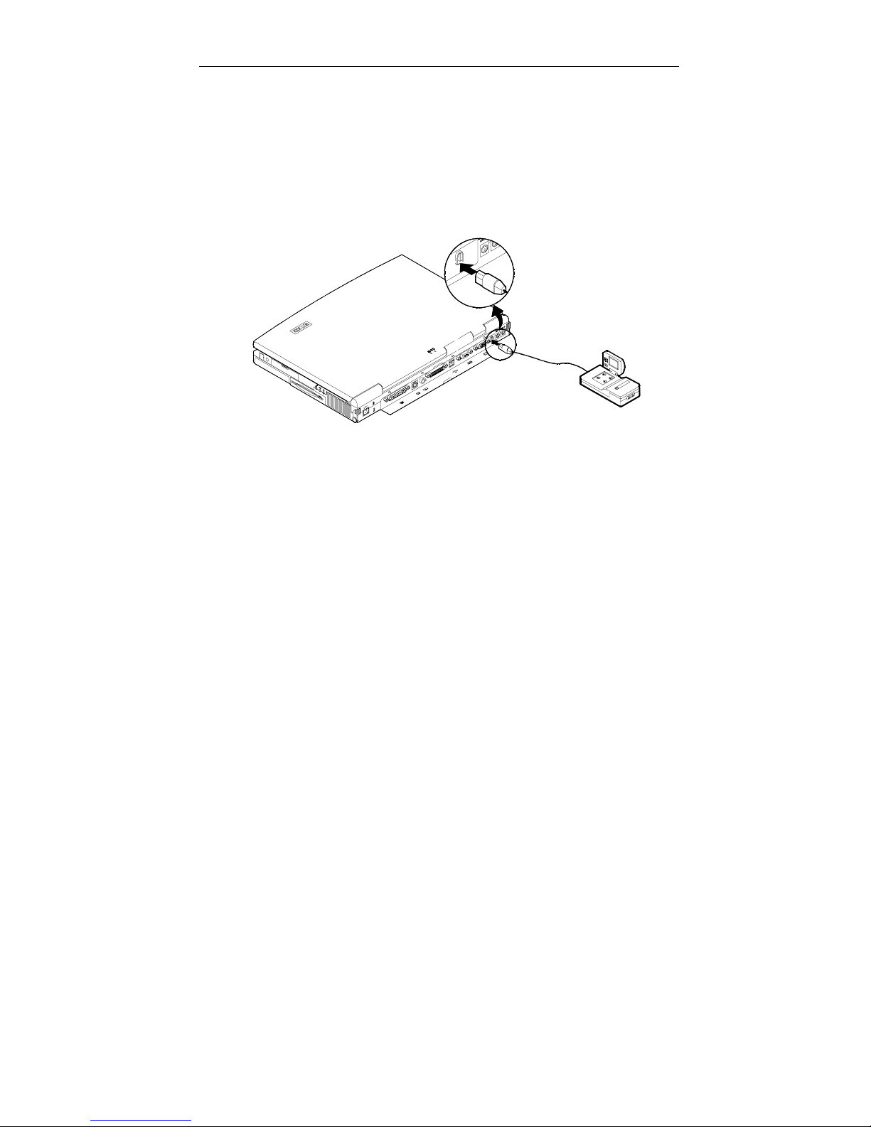
Attaching a Digital Camera
A digital camera c an be connected to the computer through the 1394 port.
However, not every type or brand of di git al c amera can be connected to the
computer. Choose the camera that comes with a specially desig ned plug
for 1394 port (Figure 2-28).
Figure 2-28
Page 66

Chapter 3 : BIOS Utilities
This chapter provides you with the information of Power On Self-Test
(POST) and shows you how to configure the s ystem param eters using the
System Configuration Utility (SCU).
Power on Self Test (POST)
!
POST Message: Normal Operation
POST Message: Error Detected
System Configuration Utility (SCU)
!
Information in the SCU
Initiating the SCU
Working with the Menu Bar of the SCU
Working with the Pull-Down Menu of the SCU
Features of the SCU
Startup Menu
Memory Menu
Disks Menu
Components Menu
Power Menu
Exit Menu
Page 67

Chapter 3: BIOS Utilities 3-55
Power on Self Test (POST)
!!!!
The system BIOS (Bas ic Input/Outpu t System) perf orms a series of Power
On Self-Test (POST) on system memory and key computer components
every time the computer is turned o n. If an error exists , the POST routin e
may halt execution (depending on the problem). If no error exists, the
POST will initializes BIOS configuration, then boots the operating system.
POST Message: Normal Operation
You will see the following message if no error exists after the POST is
performed.
SystemSoft MobilePRO BIOS Version 1.01 (2482-00)
Copyright 1983-1996 SystemSoft Corp. All Rights Reserved
233 MHz Pentium with MMX CPU
External Cache: 512KB installed
8 MB Video RAM
SystemSoft Plug-n-Play BIOS Ver.1.17.01
Base Memory 000640 Kb
Extended Memory 064512 Kb
Total Memory 065536 Kb
Auto Detecting IDE Devices[Done]
<CTRL-ALT-S> to enter System Configuration Utility
Note:
You may press the
Spacebar
key to skip the memory test.
Page 68

POST Message: Error Detected
If an error is detected , you will se e the f ollowing W ARNING mes sage. You
may press F1 key to continu e, or press the Ctrl-Alt-S keys s imultaneousl y
to enter the System Configuration Utility.
SystemSoft MobilePRO BIOS Version 1.01 (2482-00)
Copyright 1983-1996 SystemSoft Corp. All Rights Reserved
233 MHz Pentium with MMX CPU
External Cache: 512KB installed
8 MB Video RAM
SystemSoft Plug-n-Play BIOS Ver.1.17.01
Base Memory 000640 Kb
Extended Memory 064512 Kb
Total Memory 065536 Kb
WARNING – HARD DISK CONTROLLER 1 FAILURE
Auto Detecting IDE Devices[Done]
<CTRL-ALT-S> to enter System Configuration Utility
Press F1 to Continue
Page 69

Chapter 3: BIOS Utilities 3-57
System Configuration Utility
!!!!
The System Configuration Utility (SCU) is a ROM-based configuration utility
that displays the system’s configuration status and provides users with a
tool to set their system param eters. The settings are stor ed in non-volatil e
battery-backed CMOS RAM which saves the information even when the
power is turned off, and retains it when the system is turned on again
Information in the System Configuration Utility
The following sho ws the system settings that may b e changed within the
System Configuration Utility.
Menu Bar Items Pull-down Menu Items
Startup Date and Time, Fast Boot, Boot Device, Display,
Enable Battery Low Beep, Enable LCD Expand
Mode, Enable Power On Beep, Boot Password,
SCU Password.
Memory Cache Systems.
Disks Enable LS120/ZIP 100 Dr ive, Diskette Drives, IDE
Settings.
Components COM Ports, MODEM Port, LPT Port, PS/2 Mouse
Port, Microsoft IntelliMouse Support, Keyboard
Numlock, Keyboard Repeat, TV Mode, Video in
Mode, ZV Port Enabled
Power Enable Power Savi ng, Low Power Saving , Medium
Power Saving, High Power Saving, Customize,
Suspend Controls, Resum e Timer, Enable MODEM
Ring Resume, Enable Battery Low Suspend,
Advance CPU Controls.
Exit Save and Exit, Exit (No Save), Default Settings,
Restore Settings, Version Info.
.
Page 70

Initiating the System Configuration Utility
The System Configuration Utility (SCU) can be accessed when pressing
the Ctrl, Alt, and S keys simultaneously .
<CTRL-ALT-S> to enter System Configuration Utility
The above message only lasts secon ds. If you miss it, the computer will
initiate the boot proc ess. You must reboo t the system and try again within
the time limit if you want to enter the System Configuration Utility.
System Configuration Utility (SCU)
Figure 3-1
Page 71
Chapter 3: BIOS Utilities 3-59
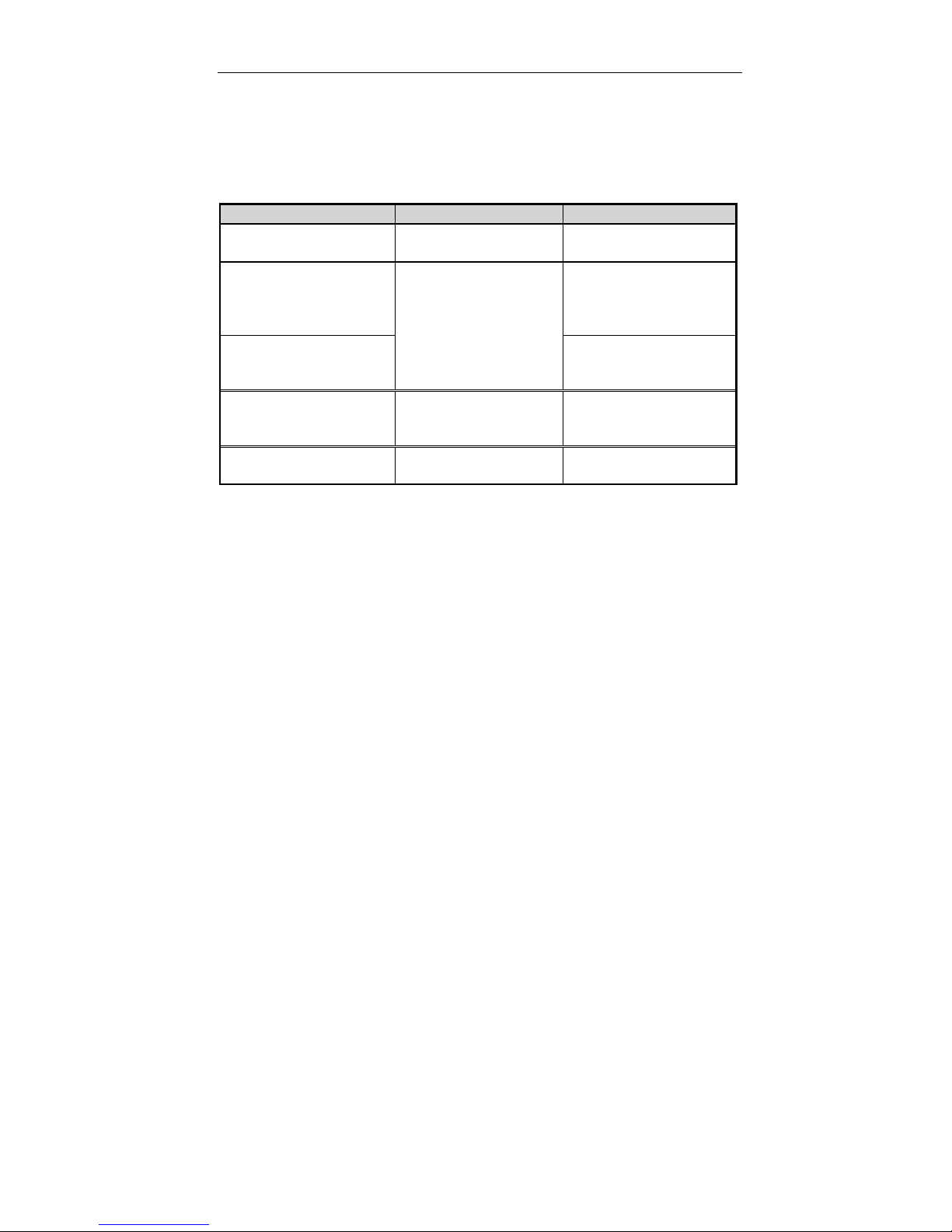
Working with the Menu Bar
After entering the SCU, you may use the following keys to work with the
menu bar.
Keys Action Description
Alt Activate menus Activate the System
Configuration Utility.
Left arrow (←)
Right arrow (→)
The highlighted letter
key
Mouse left button
Spacebar
Enter
Mouse right button
Esc
Select menu bar
item.
Accept menu bar
item
Cancel current action Undo the current
Move to a menu bar
item on the left.
Move to a menu bar
item on the right.
Move to the
corresponding menu
bar item.
Enter the selected
menu bar item to
configure settings.
command.
Page 72
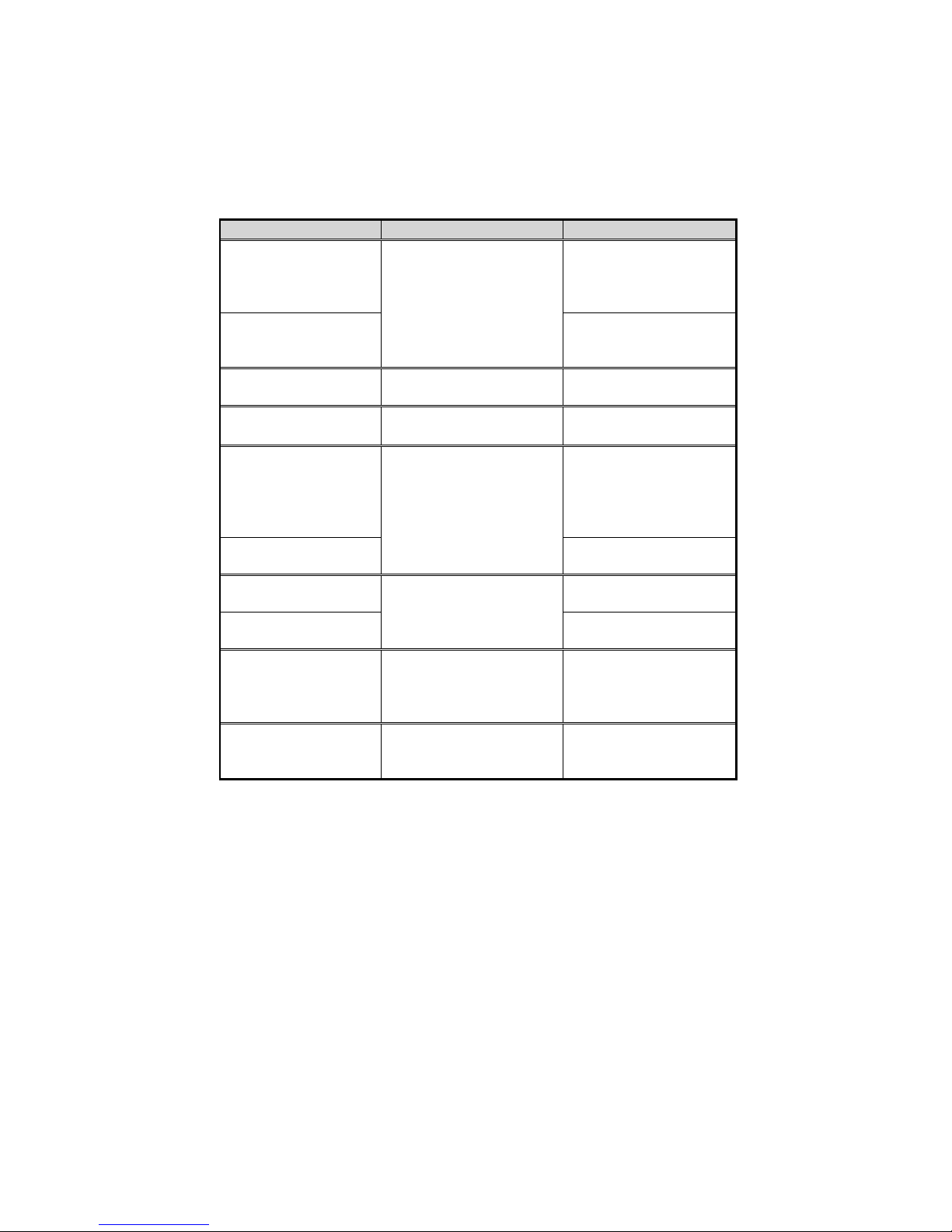
Working with the Pull-down Menu
When the desired menu bar item is highlighted, press the Enter key to
enter the pull-down menu for values setting. You may use the following
keys to work with the pull-down menu.
Keys Action Description
Down ar r ow (↓)
Up arrow (↑)
The highlighted
letter key
Tab Select a control Move between the
Down/Up arrows
(↓)(↑)
Spacebar Enable/disable the
Enter
Esc Undo the current
Enter
Alt Activate accelerators Initiate all the
Esc Quit Press the Esc key to
Select pull-down menu
item.
Change values Modify the settings.
Accept entries
Reject entries
Move to the next pulldown menu item.
Move to the previous
pull-down menu item.
Move to the
corresponding pulldown menu item.
options.
specified function.
When a check mark
(√) appears, the
function is on.
Choose <OK> from a
list of options.
setting.
Choose <Cancel>
from a list of options.
highlighted letters
corresponding to their
respective options.
close the pull-down
menu.
Page 73
Chapter 3: BIOS Utilities 3-61
Features of the System Configuration Utility
Startup Menu
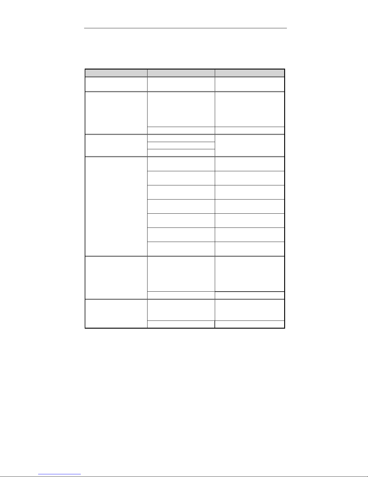
Item Setting/Option Function
Date and Time Day/Month/Year
Hour/Minute/Second
Fast Boot
Boot Device
Display
Enable Battery Low
Beep
Enable LCD Expand
Mode
Enable Initialize and quickly
Disable Disable the above.
Diskette A
Hard Disk C
CD-ROM Drive
LCD Activate the system’s
CRT Activate an external
LCD + CRT Activate both the LCD
TV Activate an external
LCD + TV Activate both the LCD
CRT + TV Activate both the CRT
LCD + CRT + TV Activate the LCD, CRT
Enable The system emits a
Disable Disable the above.
Enable Stretch the display to
Disable Disable the above.
Set the current date
and time.
boot the system in a
few seconds by
skipping certain
diagnostic tests.
Specify where the
system boots from.
LCD panel.
monitor.
and the CRT.
TV.
and the TV.
and the TV.
and TV.
series of warning
beeps sound when the
battery power becomes
low.
fill the entire viewing
area of the LCD panel.
Page 74
Item Setting/Option Function
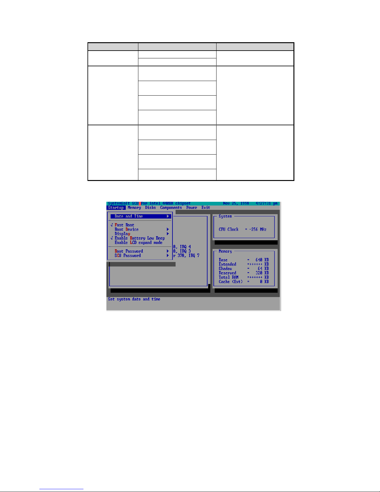
Enable Power Enable Enable or Disable Power
On Beep Disable On Beep.
Boot Password
Enter old Power-On
Password
Enter new Power-On
Password
Verify new Power-On
Set password for booting
computer. Users are
authorized to start the
system after entering
correct password.
Password
Enable Password to
Power-On
SCU Password
Enter old Setup
Password
Enter new Setup
Password
Verify new Setup
Password
Set password for
modifying SCU. Users
are authorized to c hange
the SCU setting after
entering correct
password.
Enable Setup Password
Startup Menu
Figure 3-2
Page 75
Chapter 3: BIOS Utilities 3-63
Memory Menu
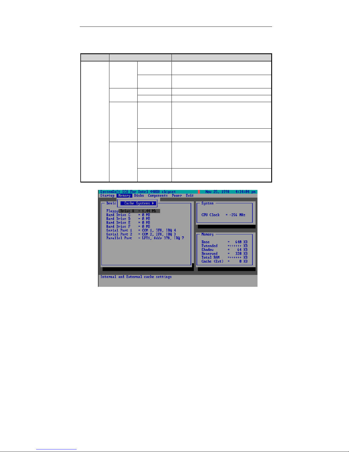
Item Setting/Option Function
Cache
Systems
L1
Cache
Cache
BIOS
Shadow
Video
Shadow
Disabled Disable the processor’s internal
cache.
Write Back Enable the Processor’s internal
write-back cache.
Disabled Disable the L2 cache controller.L2
Write Back Enable the LS write-back cache.
Cached
The process of shadowing copies
instructions from system BIOS into
RAM to improve system
performance.
Not
Disable the above.
Cached
Cached
The process of shadowing copies
instructions from video BIOS into
RAM to improve system
performance.
Not
Disable the above.
Cached
Figure 3-3
Memory Menu
Page 76
Disks Menu
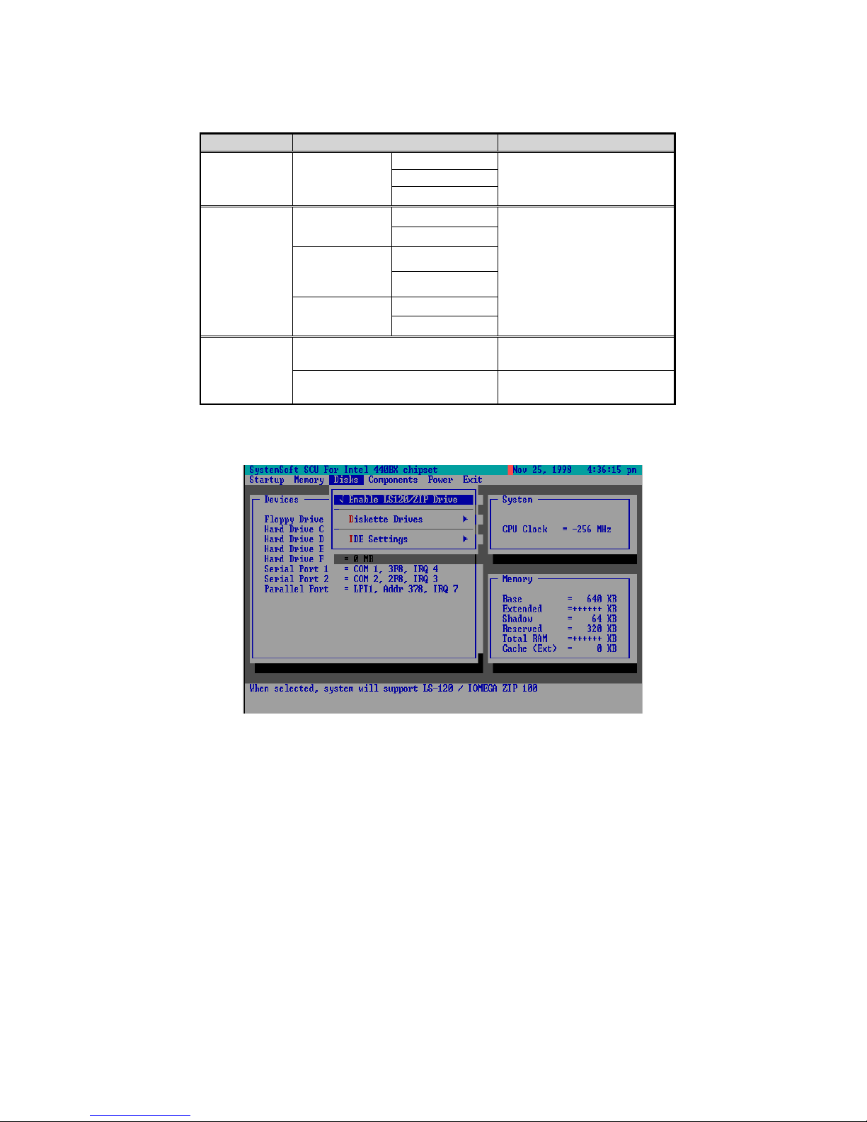
Item Setting/Option Function
NoneDiskette
1.44 Mb
2.88 Mb
Drive EnabledPrimary HDD
PIO Mode
Drive EnabledCD-ROM /
PIO Mode
Drive Enabled
PIO Mode
Specify the drive types
for the diskette drive A.
Enable enhanced IDE
settings.
drive.
ZIP drive.
Drives
IDE
Settings
Enable
LS120/ZIP
Drive
Drive A
DVD-ROM /
3rd HDD
LS120 /ZIP/
nd
2
HDD
Enable Enable the LS120 or Z IP
Disable Disable the LS 120 or
Figure 3-4
Disks Menu
Page 77
Chapter 3: BIOS Utilities 3-65
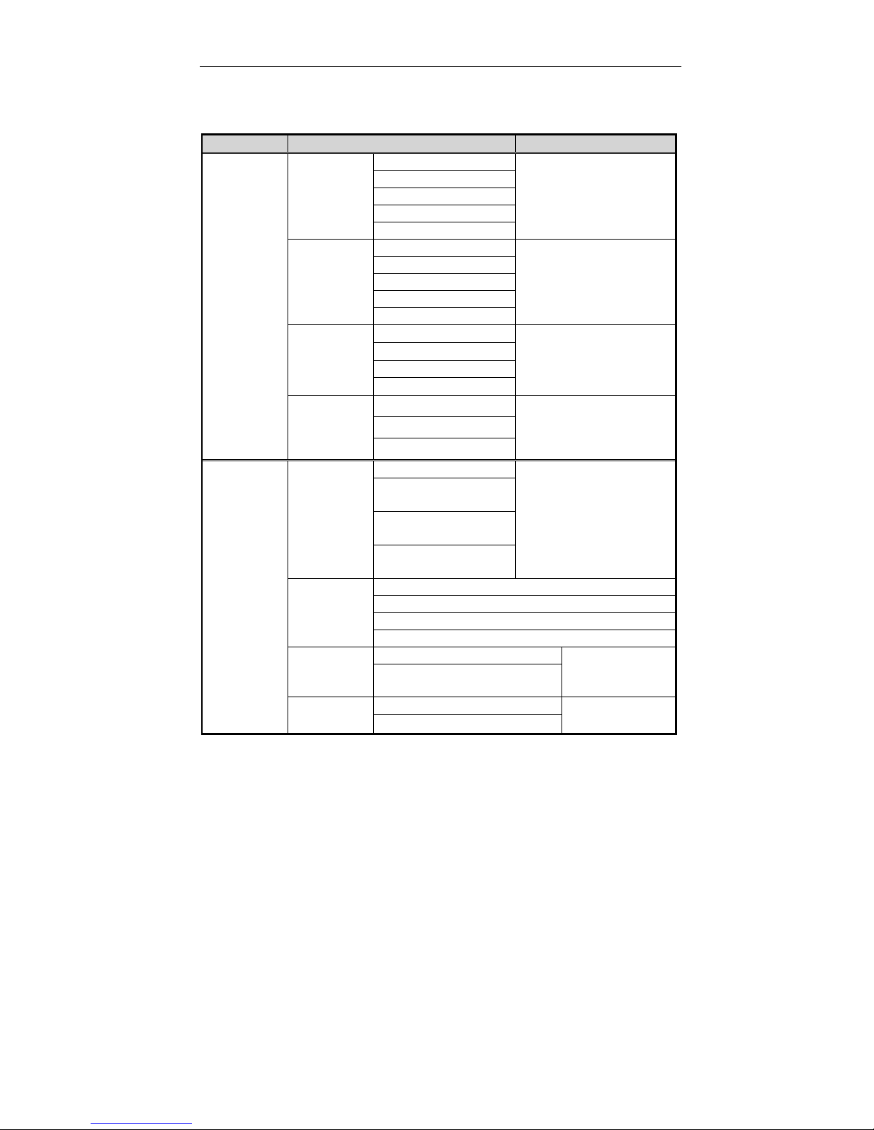
Components Menu
Item Setting/Option Function
COM
Ports
LPT Port
COM A I/O
Settings
COM B I/O
Settings
Mode
Setting for
COM B
DMA
Setting for
Fast IR
Port
Address
Port
Definition
Setting For
ECP Mode
EPP Type
None
COM1, 3F8, IRQ4
COM2, 2F8, IRQ3
COM3, 3E8, IRQ10
COM4, 2E8, IRQ11
None
COM1, 3F8, IRQ4
COM2, 2F8, IRQ3
COM3, 3E8, IRQ10
COM4, 2E8, IRQ11
Normal (16550)
IrDA (HPSIR)
Specify the COM A
configuration. (COM3
& COM4 Only for DOS
mode and Non-PnP
OS.)
Specify the COM B
configuration. (COM3
& COM4 Only for DOS
mode and Non-PnP
OS.)
Define the COM B
hardware.
ASK IR
FAST IR
DMA 0
DMA 1
Specify the Fast IR
DMA configuration.
DMA 3
None
LPT1, Addr 378,
Specify the LPT port
and IRQ configuration.
IRQ7
LPT2, Addr 278,
IRQ5
LPT3, Addr 3BC,
IRQ7
Standard AT (Centronics)
Bi-directional (PS-2)
Enhanced Parallel (EPP)
Extended Capabilities (ECP)
DMA 1DMA
DMA 3
EPP 1.7
EPP 1.9
Specify the
ECP DMA
configuration.
Specify the
EPP type.
Page 78
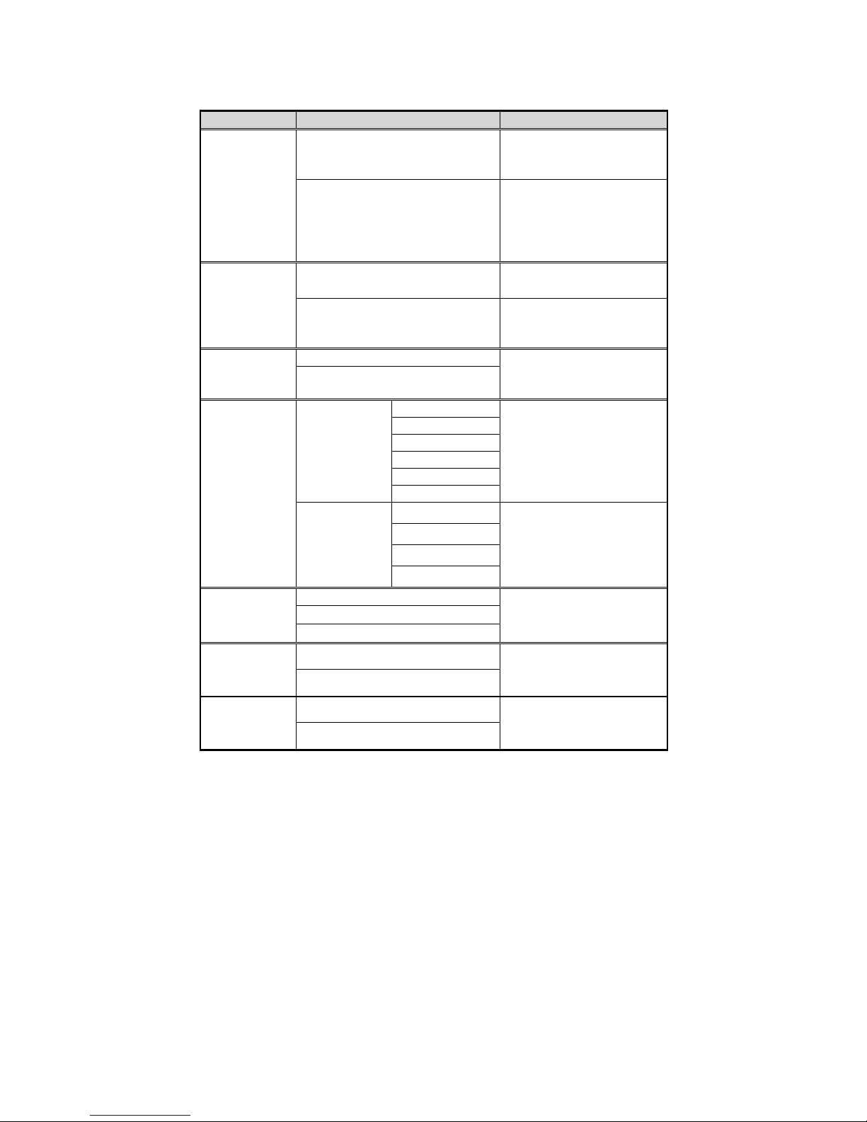
Item Setting/Option Function
PS/2 Mouse
Port
Enable Enable the system’s
trackpad or an external
PS/2 mouse.
Disable Disable the trackpad or
PS/2 mouse if an
external mouse is
connected to COM A
port.
Microsoft
Intellimouse
Support
Enable Support PS/2 mouse
with the wheel button.
Disable Do not support PS/2
mouse with the wheel
button.
Numlock
EnableKeyboard
Disable
Specify whether Num
Lock is on or off at
system boot time.
Keyboard
Repeat
Key Repeat
Rate
2 cps
6 cps
10 cps
15 cps
20 cps
Define the rate
(characters per second)
at which the keyboard
repeats while a key is
depressed.
30 cps
TV Mode
Key Delay
NTSC
PAL
1/4 sec
1/2 sec
3/4 sec
1 sec
Specify the amount of
time (second) that will
pass after a key is
depressed before the
key starts to repeat.
Specify the TV mode
selection
NTSC-Japan
Mode
DisabledVideo in
Enabled
Disable or enable the
video in mode.
Enabled
EnableZV Port
Disable
Enable or disable the
ZV port.
Page 79
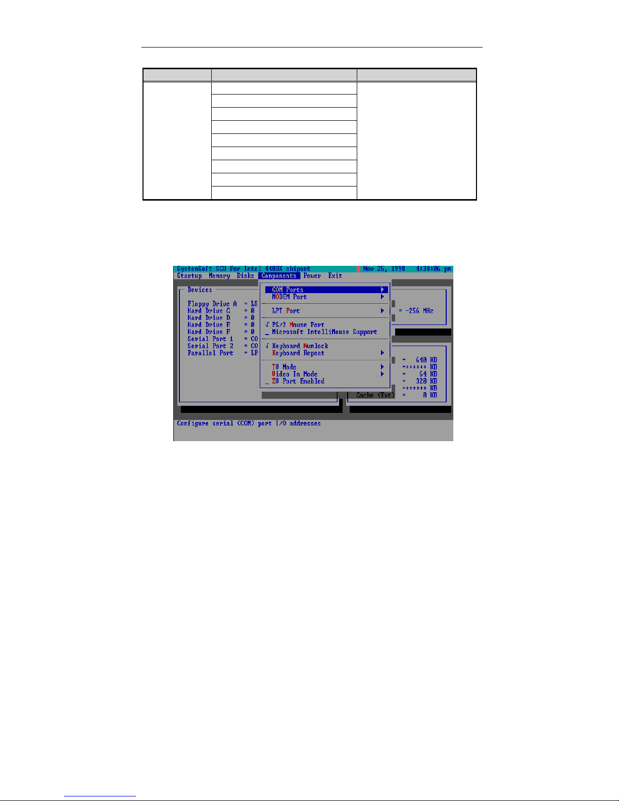
Chapter 3: BIOS Utilities 3-67
Item Setting/Option Function
Modem Port
None
Port 3E8, IRQ 11
Specify the Modem Port
settings.
Port 2E8, IRQ 11
Port 3F8, IRQ 11
Port 3E8, IRQ 9
Port 2E8, IRQ 9
Port 3F8, IRQ 9
Port 2F8, IRQ 9
Port 2F8, IRQ 11
Figure 3-5
Components Menu
Page 80
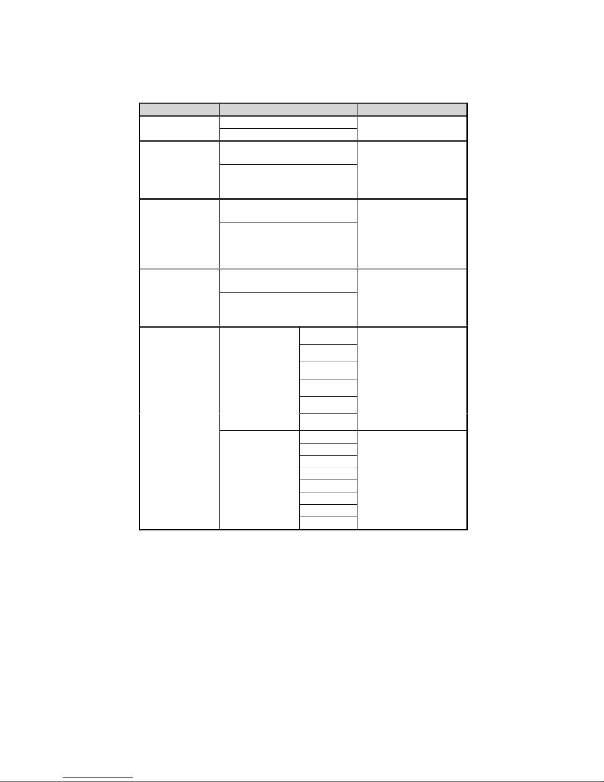
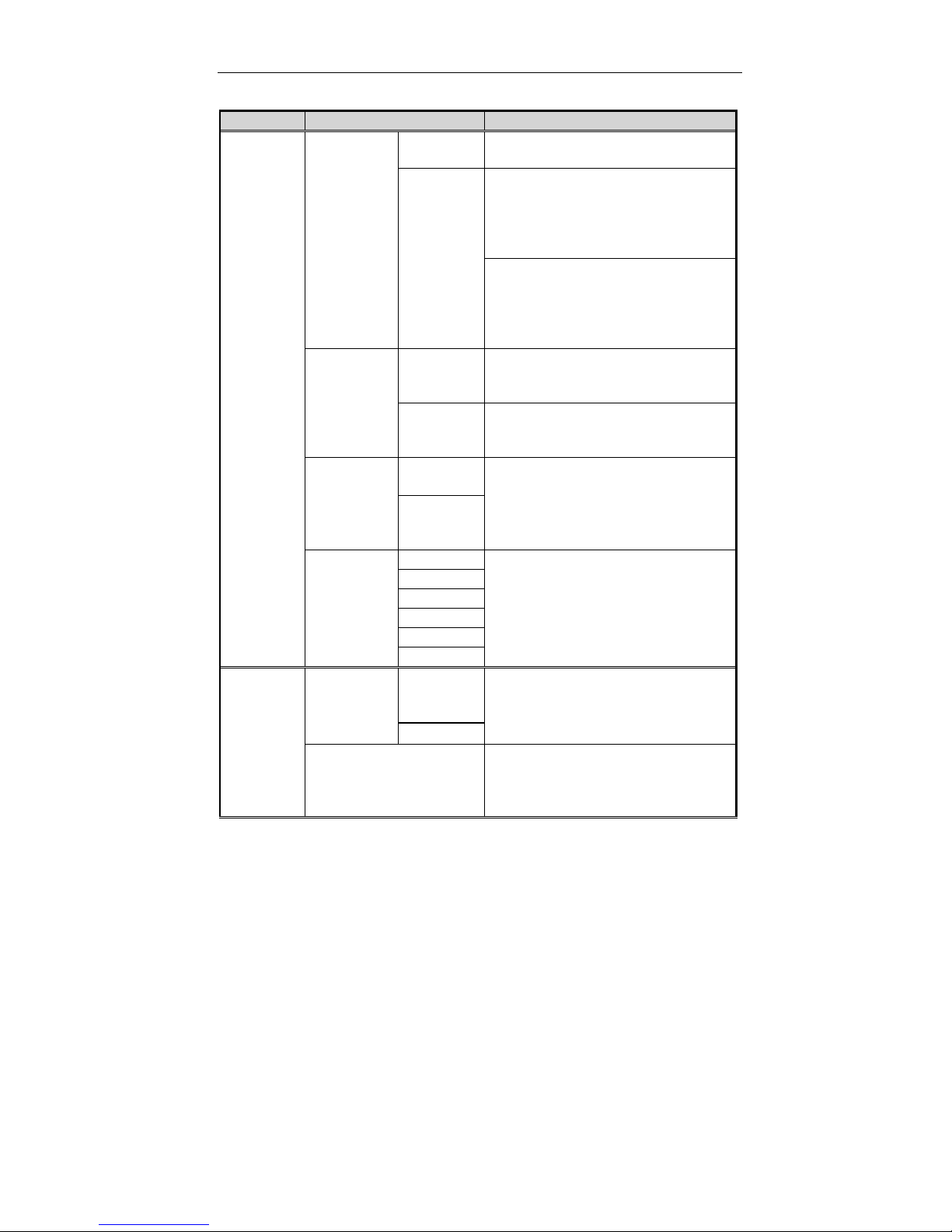
Power Menu
Item Setting/Option Function
Saving
Saving
Saving
Saving
Customize
EnableEnable Power
Disable
EnableLow Power
Disable
EnableMedium Power
Disable
EnableHigh Power
Disable
Disk Standby
5 sec
10 sec
15 sec
20 sec
30 sec
Always on
Enable/Disable all
power saving features.
Enable/Disable the
power saving to its
lowest which r esults in
max. performance but
shortest battery life.
Enable/Disable the
power saving to its
medium which results
in both moderate
performance and
battery life.
Enable/Disable the
power saving to its
highest which results
in min. performance
but longest battery life.
The hard disk will be
put on standby if it is
not accessed within
the specified period.
Hard disk power will
be restored when the
disk drive is accessed
again.
Global Timeout
1 min
2 min
4 min
6 min
8 min
12 min
16 min
Always on
The system po wer will
be reduced if the
system has been idle
over the specified
period. System power
will be restored when
any system activity is
detected.
Page 81
Chapter 3: BIOS Utilities 3-69
Item Setting/Option Function
Suspend
Controls
Power
Button
Function
Power
On/Off
Suspend/
Resume
The power button is switched to
turn the system on or off.
The power button acts as a
suspend/resume button for
switching the system between a
working state and the suspend
mode.
Pressing the power button for
more than four seconds will
generate a power button o ver-ride
event to switch the s ystem fr om a
working state to the Soft-Off state.
Lid Switch
Function
Suspend/
Resume
Enter suspend mode or resume
by closing or open ing the display
lid.
LCD
Panel
Turn the panel power on or off by
opening or closing the display lid.
Off/On
Suspend
Type
Suspend
to Disk
Specify the suspend mode for
power management.
Powered
on
Suspend
Suspend
Timeout
1 min
5 min
10 min
If the system has been i dle f or the
specified period, the system will
enter user-defined suspend.
20 min
30 min
Never
Resume
Timer
Alarm
Enable
Resume the system from the
configured suspend mode when
resume alarm timer expires.
Disable
The system will resume at the
Resume
Month/Day/Hour/Minut
e
specified time (month, day, hour
and minute).
Page 82
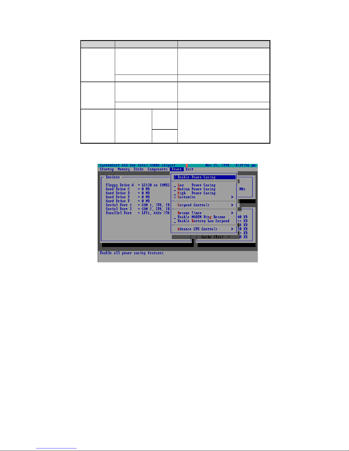
Item Setting/Option Function
Enable
MODEM
Ring
Resume
Enable Resume the system from ST R or
POS mode when a modem r ing is
detected (which modem should
be connected to the serial port).
Disable Disable the above.
Enable
Battery
Low
Suspend
Advance
CPU
Controls
Enable Automatically suspend the system
to disk upon a low battery
condition.
Disable Disable the above.
Clock
Control
Full
Mode
Specify the type of Processor
Clock Control.
Mechanism
Doze
Mode
Figure 3-6
Power Menu
Page 83
Chapter 3: BIOS Utilities 3-71
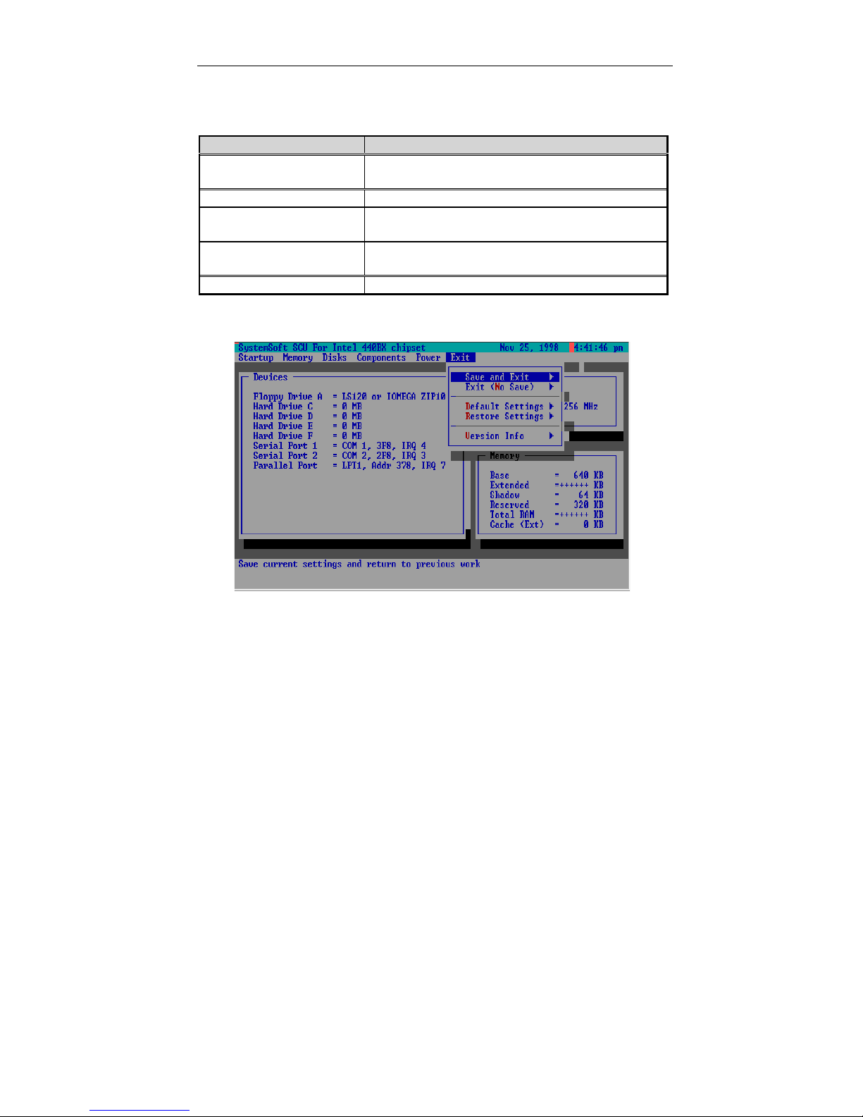
Exit Menu
Item Function
Save and Exit Save the current settings and reboot the
system.
Exit (No Save) Exit without saving any current changes.
Default Settings Restore the default se ttings (the original ones
found in ROM).
Restore Settings Restore the current setup settings to the
original custom ones.
Version Info Sho w curr ent BIO S vers i on inf or mation.
Figure 3-7
Exit Menu
Page 84

Page 85

Chapter 5: Installing Drivers 4-1
Chapter 4 : Troubleshooting
Sometimes your computer has some problems. Before you consult the
computer vendor, you can try to solve problems yourself. This chapter
provides you with a l ist of som e comm only exper ienced problem s and their
possible solutions.
! !
! !
! !
! !
! !
! !
! !
! !
! !
! !
! !
! !
Battery
Power
Hard Disk Drive
Floppy Disk Drive
Hardware Installation
LCD Panel
Memory Module
PC Card
Boot Password
Audio
CD
Printer
Page 86

Battery
!!!!
Problem: The battery pack can not be charged.
Solution 1:
Solution 2:
Problem: The battery pack can not be charged and the
Solution 1:
Solution 2:
Solution 3:
Problem: The beep sound is heard and the low-battery
Solution:
Problem: The beep sound isn’t heard whereas the low-
Solution:
The battery pack is exposed to excessively hot and cold
environment. Let it r estore to norm al condition before you
use it.
The power might be used up.
charge indicator turns off.
The battery has been fully charged.
he battery pack is exposed to excessively hot or cold
environment. Let it r estore to norm al condition before you
use it.
The power is used up.
indicator turns on.
The computer is in low-battery status. Please connect your
computer with AC adapter, or press Fn + Esc key
combination to enter suspend mode.
battery indicator turns on, or the gauge indicates
power is less than 10%.
The computer is in low battery status. Please adjust the
volume control and connect the computer with AC adapter.
Problem: The actual battery operation time is shorter than
expected.
Solution1
Solution 2
Solution 3
Solution 4
Solution 5
: The battery is exposed to excessively high or low
temperature. The ideal temperature for battery operation is
between 50°F and 95°F (10°C and 35°C) whereas keeping
is between 32°F and 113°F (0°C and 45°C).
: The battery has released some power. Please recharge it.
: The power management has been turned off.
: Some peripheral device or PC card is consuming power.
Turn off the unused device to save power.
: The battery has been given a partial charge. When
charging, always fully charge after fully discharge.
Page 87

Chapter 5: Installing Drivers 4-3
Power
!!!!
Problem
Solution 1
Solution 2
Problem
Solution 1
Solution 2
!!!!
Problem
Solution
Problem:
Solution 1:
Solution 2:
:
:
Hard Disk Drive
:
: The computer is trying to boot fr om the f loppy inclu ding no
The computer can not boot when the battery pack is
not inserted.
: T he po wer cor d is not c orr ect ly c onn ec ted wit h AC ad apter.
Make sure the power cord is f irmly plugged into grounde d
outlet and computer.
: The grounded outl et is not in normal oper ation. Check the
outlet’s function or use other outlet.
The system has automatically entered susp end mod e
: The system’s temperature is too high. Let it cool before
you use it.
: The system has entered suspend mode after a specified
period of time. Please press an y ke y or touch th e track pad
to wake up the computer.
The message “Nonsystem disk” appears.
software. Please take the floppy out and restart the
computer.
It needs a longer time to read the hard disk drive after
restarting the computer
The data saved on hard disk drive may be lost. Please
operate the “disk defragmenter” to check the lost unit.
As in low battery status, the computer is waking up from
the suspend mode.
.
.
Page 88

Floppy Disk Drive
!!!!
Problem: The floppy disk drive can not write data to disk.
Solution 1:
Solution 2:
Solution 3:
Solution 4
The floppy is not formatted.
The floppy is write-protected. Please cancel the protection.
The data is written to incorrect disk drive.
: The space left on disk is not enough. Please use a new
disk or delete the unneeded data.
Problem
Solution 1
Solution 2
Solution 3
!!!!
Problem:
Solution 1
Solution 2:
Solution 3
Solution 4
:
Hardware Installation
The disk drive can not read the disk.
: The disk is not formatted.
: The disk is damaged.
: An incorrect disk type is used.
The computer can not recognize the device as part of
the system.
: The power switch of new de vice is not turned on. Pleas e
turn on the power switch, then restart the computer.
You do not rearrange the computer after the device is
installed.
: The power cord or the connector between device and
computer is plugged out. Please make sure the dev ice is
firmly connected with the computer.
: You do not follow the system c onf igurati on as the c omputer
suggested. Please follow the suggestion.
Page 89

Chapter 5: Installing Drivers 4-5
LCD Panel
!!!!
Problem: The font is too dark.
Solution:
The brightness or contrast is not correctly set. Please
press Fn+F7 or Fn+F8 key combination (only limited to
DSTN panel) to adjus t the cont rast contro l, and use Fn+F9
or Fn+F10 to adjust the brightness control.
Problem:
Solution 1:
Solution 2:
Solution 3:
Solution 4:
Problem:
Solution:
The resolution you use for the monitor exceeds that the
The screen is blank.
The panel blank application might be set.
The system operates the screen saver after a specified
period of time. Please press any key or touch the
trackpad.
The brightness or contrast needs to be adjusted. Please
press Fn+F7 or Fn+F8 key combination (only limited to
DSTN panel) to adjus t the cont rast contro l, and use Fn+F9
or Fn+F10 to adjust the brightness control.
The system has entered susp end m ode. Pl ease press an y
key or touch the trackpad to wake up the computer.
The LCD panel displays incorrect font or blinks when
the computer is connected with an external monitor.
LCD panel can suppor t whereas you have switched to the
LCD panel. Please restart the computer.
Page 90

Memory Module
!!!!
Problem: The computer can not boot.
Solution:
The incorrect type of memory module is installed.
Problem:
Solution:
Problem:
Solution:
Problem:
Solution:
Problem:
Solution:
!!!!
Problem:
Solution:
Problem:
Solution 1:
Solution 2:
Solution 3:
The memory is not correctly configured for the application.
Some memory module is not correctly installed or not
The memory configuration is not correctly set or the
The application ca n n ot b e op er ate d as t he memory is
PC Card
The PC card is not supported.
The PC card driver is not installed.
The PC card or card driver is not compatible with the
The memory capacity is not enough.
The detected memory capacity is not correct.
compatible with your com puter.
The message “out of memory” is displayed.
memory is not enough to run the application.
The message “insufficient memory” is displayed.
used up.
The PC card can not be configured.
The system can not recognize the PC card.
The PC card is not inserted into the socket or reversely
inserted.
computer.
Problem:
Solution:
The beep sound is not heard while the PC card is
inserted.
The beep sound control is closed.
Page 91

Chapter 5: Installing Drivers 4-7
Boot Password
!!!!
Problem:
Solution:
!!!!
Problem:
Solution:
Problem:
Solution:
Problem:
Solution 1:
Solution 2:
Solution 3:
While forgetting the password, you m ust unpack the
Audio
The volume might be set too low. Please check your
The volume is not correctl y set. P lease check your volum e
You forget the boot password.
computer and delete the m emory. Please ask the ven dor
for help
The audio speaker can not be heard.
volume control.
The volume is too high (or too low).
control.
The headphone can not be heard.
The volum e is not correctl y set. Please check the vo lume
control.
The volume source is not chosen.
The headphone is plugged into the wrong jack.
Page 92

CD-ROM
!!!!
Problem:
Solution:
Problem:
Solution 1:
Solution 2:
Problem:
Solution:
Problem:
Solution 1:
Solution 2:
Solution 3:
The compact disk is not correctly placed in the tray.
The compact disk hardware for reading data needs to be
The compact disk can not be exited.
The compact disk can not be read
The compact disk is not correctly placed in the tray.
The compac t disk is dirty. Please clean it with a CD-ROM
cleaner kit.
The musical compact disk can b e read while the data
disk can not.
checked.
All compact disks can not be read.
The Windows system c an not rec ogn i ze t he C D- RO M dri ve
or the CD-ROM drive is not compatible with other devices.
The compact disk is dirty. Please clean it with a CD- ROM
cleaner kit.
The compact disk hardware f or reading data needs to be
checked.
.
Page 93

Chapter 5: Installing Drivers 4-9
Printer
!!!!
Problem:
Solution:
Problem:
Solution 1:
Solution 2:
Solution 3:
Solution 4
Solution 5:
Problem:
Solution 1:
Solution 2:
ATI DVD Play (option)
!!!!
Problem:
Solution:
The printer can not be set up
The printer power cord is not plugge d into or the connec tor
is not correctly connected.
The printer can not work.
The printer is not power on. Please turn on the printer.
The printer is not in “connected” status. Please set the
printer in “connected” status.
The printer paper is used up. Please add the paper.
: The printer driver is not installed or correctly chosen.
Please check the system.
The printer for network is not connected with the network.
The printer prints incorrect data.
The printer driver is not installed or correctly chosen.
The printer power cord is not plugged i nto or the co nnector
is not correctly connected.
Please avoid pressing the Hot keys quickly and
When the DVD station is playing, pressing (Fn)
hot keys quickly at the s ame time, the D VD station will
stop running in the normal Windows system.
continuously. For example, when use the Fn ke y, stopping
seconds each time before pressing again. Or go to
Windows 95/98, clic k the ic on of volume at the r igh t- bott om
corner the voice volum e.
.
Page 94

Chapter 5 : Installing Drivers
This chapter provides users the step-by-step instructions of installing
device drivers and utilities. Infor mation has been designed to sui t for the
users who has the basic computer knowledge. However, the
inexperienced users also can get good help from the instruction.
Installing Windows 95
!
Installing Windows 98
!
Installing Drivers in Windows 95
!
Installing Drivers in Windows NT4.0
!
Installing Drivers in Windows 98
!
Page 95

Chapter 5: Installing Drivers 5-11
Installing Windows 95
!!!!
Preparation for instal l i ng Wi ndo ws 95:
1. Use a bootable f l oppy disk to start th e system.
2. Run FDISK utility from DOS to create a bootable partition.
(See DOS manual for the operation detail.)
3. Format hard disk. Follow the command “Format C:/S” to create a
bootable hard disk and make the boot system file.
(C;/S copies sy stem files to the formatted disk)
4. Run CDINST.COM program from the “CD-ROM Drive Installation
Diskette” that will help you to install CD-ROM driver device
automatically. See the driver manual for detail.
5. Restart the system.
1. Start DOS.
2. Insert the Windows 95 CD-ROM.
3. Go to the “setup” directory, type “setup”, then press [Enter].
4. After the Windows 95 setup program performs a routine check on your
system, press [enter] to continue.
5. When the “Welcome to Windows 95 Setup” screen appears, click
“Continue”.
6. Click “Yes” on the “License Agreement” screen.
7. Click “Next” to select “Collecting Information About your PC”.
8. Click “Next” to select the default of “C:\Windows”, or enter a different
directory.
9. On the screen of “Setup Options”, select “Typical”, then click “Next”.
10. On the screen of “Certificate of Authenticity”, enter the Product
Identification Number, then click “Next”.
11. On the screen of “User Information”, enter your name and company,
then click “Next”.
12. Select “Install The Most Com m on Com ponents (rec om mended) ”, then
click “Next”.
13. On the screen of “Startup Disk”, insert a blank dis kette into the A drive
to create a startup diskette.
14. The Setup Wizard is now copying files. After the copying is finished,
Page 96

remove the disk, then click “OK”.
15. Click “Next” to start copying Windows 95 files to your computer.
16. Click “Finish” to restart Windows 95.
17. On the screen of “Set Up a Printer”, click “Cancel”.
Note:
Do not install a printer at this t im e. You will not be able to acc es s the
Windows 95 Installation CD until you reboot.
18. Click “OK” to restart the computer.
Page 97

Chapter 5: Installing Drivers 5-13
Installing Windows 98
!!!!
1. Start DOS.
2. Insert the Windows 98 CD-ROM.
3. Type “setup”, then press [Enter].
4. Follow the instructions on the screen and choose the recommended
option.
5. The Windows 98 setup program will check the hard disk drive
automatically.
6. When the setup initializes, click “Continue”.
7. Choose “License Agreement” to agree the contrast.
8. Click “Next” to type the product ID number.
9. Click “Next” . The program will automatically check the system.
10. Choose the directory for your computer. Select the path of
“C:\Windows”, or type another path.
11. For reinstallation, choose “Yes” (recommended) to keep the files.
12. Sel ect your loc at ion.
13. To create a Win98 Startup disk, insert a floppy disk into drive A. To
create the startup disk later, choose “cancel”.
14. Press “Next”. The program will copy files to your computer’s hard disk.
15. At the same time, the screen will show the Win98 concerned
information and the setup items one by one.
16. After the automotive setup stops, restart the computer.
Page 98

Installing Drivers in Windows 95
!!!!
Step 1: Installing USB Driver
Down load “USB supplement path update fi le” from Micr osoft and Intel
#
web site.
Run “USB supplement path” to install the driver.
#
Step 2: Installing TXPATCH Driver
Locate the driver “[TXP ATCH] Intel 82371xb.inf TX” from the CD-ROM.
#
Run “setup.exe”.
#
Follow the instruction to finish the installation.
#
Restart the system.
#
Step 3: Installing VGA Driver
Double click “Start”.
#
Select “Run”.
#
Open the path “D:\WIN9X\setup.exe.
#
Run “setup.exe” to finish the installation.
#
Note:
If ATI VGA driver has existed in WIN95 system, click “Start”, select “Run”,
open the path “atiuinst-clean”, and then double-click “OK” to finish
installation.
Page 99

Chapter 5: Installing Drivers 5-15
Step 4: Installing Audio Driver (1978S M2E)
Double click “Start”.
#
Select “Setting”.
#
Click “Control Panel”/”S yst em”/”Device Manager ”.
#
Select “Other devices”.
#
Remove “Unknown Device”.
#
Click “OK”, then restart the system.
#
After entering into WIN95 system, the program will autom aticall y go to
#
the “Add New Hardware Wizard” (PCI Multimedia Audio Device).
Click “next”/”Other locations”.
#
Click “Browse” to locate the audio driver fr om the CD-ROM. (T he path
#
is :\Audio\WIN95.)
Click “Ok”.
#
Click “Finish” to set up the first audio driver.
#
Step 5: Installing PCMCIA driver
Double click “Start”.
#
Select “Setting”.
#
Click “Control Panel”/”system”/”Device Manager”.
#
Select “Other devices”.
#
Remove “PCI CardBus Bridge”, and then click “OK”.
#
Open “Control Panel”.
#
Select “Add New Hardware”.
#
Click “Add PCMCIA socket”.
#
Locate the file “pcmcia.inf” from the disk or CD-ROM.
#
Select “PCI-1225 CardBus” from “Texas Instrument”.
#
Click ‘next”/”next”/”Finish”.
#
Before restarting the system, copy the file “PCMCIA.inf” to
#
“C:\windows\inf”.
Note:
Copy “cbss.vxd”, “pccard.vxd” & “pci.vxd” to c:\windows\system.
Page 100

Step 6: Installing Video-in Driver
Boot the system, press Ctrl + Alt + S to enter SCU system.
#
Select “Components”.
#
Enable “Video In Mode”.
#
Under Windows 95, double click “Start”.
#
Select “Run”.
#
Open the path “D:\video-in\setup.exe.
#
Run “setup.exe” to finish the installation.
#
Step 7: Installing ATI DVD Play Driver (Option)
Note:
Make sure that you have already successfully installed the VGA Driver,
Audio Driver and DirectX5 or DirectX6 beforehand.
Boot the system ; press Ctrl+Alt+S keys to enter SCU. Select [Power]
#
menu. Enable [Low Power S avin g], or s elect [Advanc e CPU c ontrol] to
set [Full Speed]. (If the clock speed of the Intel Pentium II is above
366MHz/400MHz or if your DVD runs smoothly, you can skip this
step).
From the Windows 95/98 task bar, click [Start] button; se lect [Settin gs],
#
[Control Panel], and then click [System]. Click the tap [Device
Manager]; select [CDROM], and click the item including the type of
[DVD-ROM], Click the tap [Setting]; and then enable [DMA] check box.
Insert the CD of ATI DVD Play application and the program will
#
automatically run t he installation until fin ished. Otherwise, click [Start]
button from the Windows 95/98 taskbar. Select [Run]. Type
[D:\Atiplay\setup.exe] and click OK to finish the installation.
Step 8: Using Infrared Wireless Communication
Please refer to the readme file under the FIR directory.
#
 Loading...