

EUROCOM 6X00 Service Manual

Model 6X00
Preliminary Service Manual
November 199 6

Notice
Updating or revising this manual or making any changes to the information herein will be
initiated when the company deems it necessary. The company reserves the right to take the
above-mentioned actions and is under no obligation to notify any person of such actions in
advance or afterwards.
1996
Trademarks
MS-DOS, Microsoft Windows, and Microsoft Mouse are registered trademarks of Microsoft
Corporation.
IBM PC, OS/2, PS/2, EGA, and VGA are registered trademarks of International Business
Machines, Inc.
Intel, Pentium are trademarks of Intel Corporation.
SystemSoft is a registered trademark of SystemSoft Corp.
Sound Blaster Pro is a trademark of Creative Labs, Inc.
Duracell is a registered trademark of Duracell Inc.
Photo CD is a trademark of Eastman Kodak Company.
Other brand and product names are trademarks and/or registered trademarks of their respective
companies.

Table of Content
Chapter 1: Introduction
Overview .................................................................................................................. 1
Specifications.............................................................................................................2
LED Indicators ................................................................................................3
Power Switch Button...................................................................................... 3
Microphone 3
System Status LCD Bar................................................................................4
Top -Front View...............................................................................................6
LCD Panel.......................................................................................... 6
System Status LCD Bar....................................................................6
Dual Stereo Speakers........................................................................6
Trackpad Pointing Device.................................................................. 6
Windows 95 Keyboard....................................................................... 6
Right View ....................................................................................................8
Right-Side Stand................................................................................8
Microphone -in Jack............................................................................8
Line -in Jack........................................................................................8
Headphone Jack.................................................................................8
Infrared............................................................................................... 8
PC Card Type III Expansion Slot........................................................8
CD-ROM Drive................................................................................... 8
Ventilation........................................................................................... 8
Rear View....................................................................................................... 10
DC-in Socket...................................................................................... 10
Serial Port........................................................................................... 10
Expansion Port................................................................................... 10
RCA Jack........................................................................................... 10
External Monitor (CRT) Port............................................................... 10
MIDI/Game Port.................................................................................. 10
Parallel Port........................................................................................10
External Keyboard or PS/2 Mouse Port.............................................10
Left View ...................................................................................................... 12
Left-Side Stand................................................................................... 12
Battery Latch...................................................................................... 12
PC Card Type II Expansion Slot .........................................................12
2.5” Hard Disk Drive........................................................................... 12
3.5” Floppy Disk Drive........................................................................12
Internal Battery Pack.......................................................................... 12
Power.........................................................................................................................14
AC Power....................................................................................................... 14
Internal Battery Power....................................................................................15
Duracell Smart Batte ry at Retails......................................................16
Second Battery Power (Option) .....................................................................17
Duracell Smart Battery at Retails...................................................... 18
Operation .................................................................................................................. 19
Hardware Configuration.................................................................................19
2

CPU ................................................................................................... 19
Speed of CPU........................................................................19
Power of CPU........................................................................19
MPEG Accelerator Card (Option)...................................................... 19
RAM Configuration.............................................................................21
TV Output........................................................................................... 22
The Keyboard.................................................................................................24
System Function Key .........................................................................24
Cursor Control Keys ..........................................................................24
Embedded Numeric Keypad.............................................................25
Hot Keys.............................................................................................26
Expanded Display Mode .........................................................26
Display Type........................................................................... 26
Contrast Control.....................................................................26
Brightness Control.................................................................26
Volume Control...................................................................... 26
Contrast/Brightness Saved....................................................26
Suspend Mode .......................................................................26
New Keys for Windows 95................................................................27
Application Key....................................................................... 27
Windows Keys....................................................................... 27
Storage Disks 28
3.5” Floppy Drive................................................................................29
2.5” Hard Disk Drive........................................................................... 31
5.25” CD-ROM Drive.........................................................................33
PC Cards Slots.......................................................................................................... 34
LCD Panel...... ............................................................................................................36
Power Management................................................................................................... 37
Standby Mode .................................................................................................37
Suspend Mode ...............................................................................................37
Suspend to Memory........................................................................... 37
Suspend to Disk .................................................................................37
System Resume............................................................................................38
Resume from Suspend -to-Memory Mode.........................................38
Resume from Suspend -to-Disk Mode...............................................38
Advanced Power Management.................................................................................. 39
3

Chapter 2: Utilities
Overview....................................................................................................................41
Power On Self Test (POST).....................................................................................41
POST Messages - Normal operation............................................................42
POST Messages - Error Detected................................................................43
System Configuration Utility (SCU)............................................................................44
Invoking the System Configuration Utility....................................................... 44
Working with the Menu Bar of the SCU.........................................................45
Working with the Pull -Down Menu of the SCU..............................................45
Features of the System Configuration Utility.................................................46
System Menu.....................................................................................46
Devices Menu .....................................................................................47
Power Menu .......................................................................................49
Exit Menu............................................................................................51
Power On Self Test Definitions.................................................................................52
Debug Codes for PnP BIOS...................................................................................... 53
Debug Codes for PCI BIOS....................................................................................... 53
Error Codes Returned by APM Sub-functions........................................................... 54
4

Chapter 3: Technical View
Overview....................................................................................................................55
System Block Diagram.............................................................................................. 56
Chips ..........................................................................................................................57
SiS5101 PCI Cache memory Controller .......................................................58
SiS5102 PCI Local Data Buffer...................................................................... 59
SiS5103 System I/O & PMU.......................................................................... 60
SMC FDC37C669FR I/O FDD Controller with IR.......................................... 62
Omega 82C094 PCMCIA Host Adapter Controller........................................64
ESS ES1788 AudioDrive ................................................................................65
ESS ES690....................................................................................................66
ESS ES981 Wavetable Sample Set ROM....................................................67
Trident Cyber9385 Flat Panel Controller........................................................68
Standard Video Modes .......................................................................69
Extended Video Modes....................................................................... 70
Video Mode Cross Reference ............................................................72
Accessories ...............................................................................................................73
Battery............................................................................................................73
Toshiba Ni-MH Rechargeable Battery ................................................73
CD-ROM........................................................................................................74
TEAC CD -46E-900............................................................................74
TEAC CD -36E-900............................................................................75
TEAC CD -38E-900............................................................................76
3.5” Floppy Disk Drive....................................................................................77
Panasonic JU -226A03F.....................................................................77
TEAC FD -04HF-1300.........................................................................78
LCD Panel...................................................................................................... 79
Sanyo LM-JA53 -22NTK 12.1” DSTN..................................................79
Samsung LT104S4 -151 10.4” TFT....................................................80
NEC NL8060AC26 -04 10.4” TFT.......................................................81
Hosiden HLD1201-0151XX 12.1” TFT ...............................................82
Samsung LT121S1 -103 12.1” TFT....................................................83
NEC NL8060BC31 -01 12.1” TFT.......................................................84
5

Chapter 4: Parts List & Circuit Diagram
Parts List....................................................................................................................85
Top Case & Assemblies................................................................................86
Bottom Case & Assemblies ..........................................................................88
10.4” Display Panel & Assemblies................................................................90
12.1” Display Panel & Assemblies................................................................92
CD-ROM........................................................................................................94
FDD................................................................................................................95
HDD ................................................................................................................96
Battery Pack................................................................................................... 97
Circuit Diagrams ........................................................................................................98

Chapter 1: Introduction
Overview
The Notebook Computer has many advanced features to help you with your computing work.
This chapter describes each of the Notebook Computer’s hardware features in detail and shows
you how to use them. It covers:
: Specifications.
: The LED Indicators.
: Button.
: System Status LCD Bar.
: Input/Output.
: Power.
: Hardware Configuration.
: The keyboard.
: The Storage Disks.
: The PC Card Slots.
: The LCD Panel.
: Power Management.
1

Specifications
The state-of-the-art Notebook Computer offers a host of features specially designed to enhance
performance and usability:
Architecture PCI local bus 2.1
CPU
BIOS
Second Memory
DRAM
Power Management
Intel Pentium
Plug & Play 1.0a
Two banks
APM 1.1
Display
PC Card ZV-port support Type IIx3 or
LCD panel
Resolution
Video DRAM
VPM provider
Multiple Input/Output Trackpad 1 (PS/2)
Expansion port 1 (168 pin)
Infrared 1 (IrDA/ASKIR)
MIDI/Game port 1
Audio System Compatibility Sound Blaster Pro
Microsoft Windows Sound System
MPU-401
General MIDI
Digitized sound 16-bit stereo
Synthesized music FM sy nthesizer
Wave Table synthesizer (1MB ROM)
Input/Output Microphone-in
Line-in
Headphone
Built-in speakers 2
Built-in microphone 1
Keyboard Windows 95
Storage Hard disk 2.5”, transfer rate up to PIO Mode 4
Floppy disk 3.5”, 1.44MB high density
CD-ROM 5.25”, IDE
AC/DC Power AC input 100∼240VAC, 47∼63Hz, 1.2A
DC output 20V, 1.5A
Charger output 12∼19V, 1.4A
Total output 50W
Battery Power Type Ni-MH
Voltage 12V
Capacity 3000/3500 mAh (10 cells)
Physical Dimension 302mm (w) x 234mm (d) x 54mm (h)
Weight 3.4Kg
Serial port 1 (high speed 16C550 compatible)
Parallel port 1 (EPP/ECP mode support)
External monitor port 1
External PS/2 port 1
RCA jack 1 (NTSC/PAL TV -output)
75/90/100/120/133/150/166/200 MHz
256KB flash ROM
256KB synchronous cache
8MB up to 72MB (8/16/32/40MB)
Standby mode
Suspend to memory
Suspend to disk
TFT/DSTN
800 x 600 (SVGA)
2MB
VPM 1.1
Type IIx1 + Type IIIx1
2

LED Indicators
Two LED indicators are integrated to alert you of the system’s power status.
Color of Light Status
Green System power on (either by AC or by battery)
Red Battery in charge
Orange Battery in charge when system power on
Color of Light Status
Green Internal battery fully charged
Red Second battery fully charged
Orange Both batteries fully charged
Power Switch Button
This button is used either to turn the system on or to turn it off.
Microphone
This is a built-in input device for audio system.
3
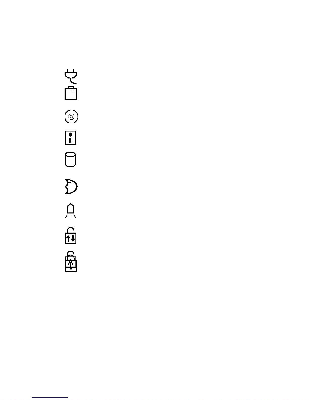
System Status LCD Bar
The Notebook Computer features a LCD panel bar to display the system’s operation status.
AC Power in Use The system is using AC power for operation.
Battery Low (Flash) The battery power is reaching a critically
low level.
CD-ROM in Use This ind icator displays that the CD-ROM
drive is being accessed.
FDD in Use This indicator displays that the floppy
disk drive is being accessed.
HDD in Use This indicator displays that the hard disk
drive is being accessed.
Suspend to Memory This indicator displays that the system
has entered the Suspend to DRAM Mode.
Turbo Speed This indicator displays that the system is
running in the maximum speed of the
CPU.
Scroll Lock This indicator displays that the scroll lock
function is activated.
Caps Lock This indicator displays that the caps lock
function is activated.
4
5

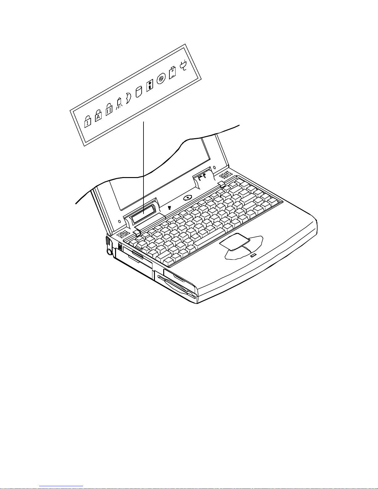
Top-Front View
Opening the hinged top cover of the system unit will reveal the followings:
LCD Panel
This is the Notebook Computer’s flat panel display. It is VGA compatible and driven
by a PCI local bus controller for high performance.
System Status LCD Bar
The LCD panel bar will display the system status indicating the respective
concerned icons.
Dual Stereo Speakers
These are two built-in output devices on each side for audio system.
Trackpad Pointing Device
The trackpad pointing device features a sensitive glide pad for precise control of the
cursor with just a fingertip along with two buttons.
Windows 95 Keyboard
The Windows 95 keyboard gives the user a consistent mechanism for accessing
functionality in Windows 95 and in individual applications.
6
LCD panel
Dual Stereo speakers
LCD bar
Windows 95 keyboard
Trackpad and buttons
7

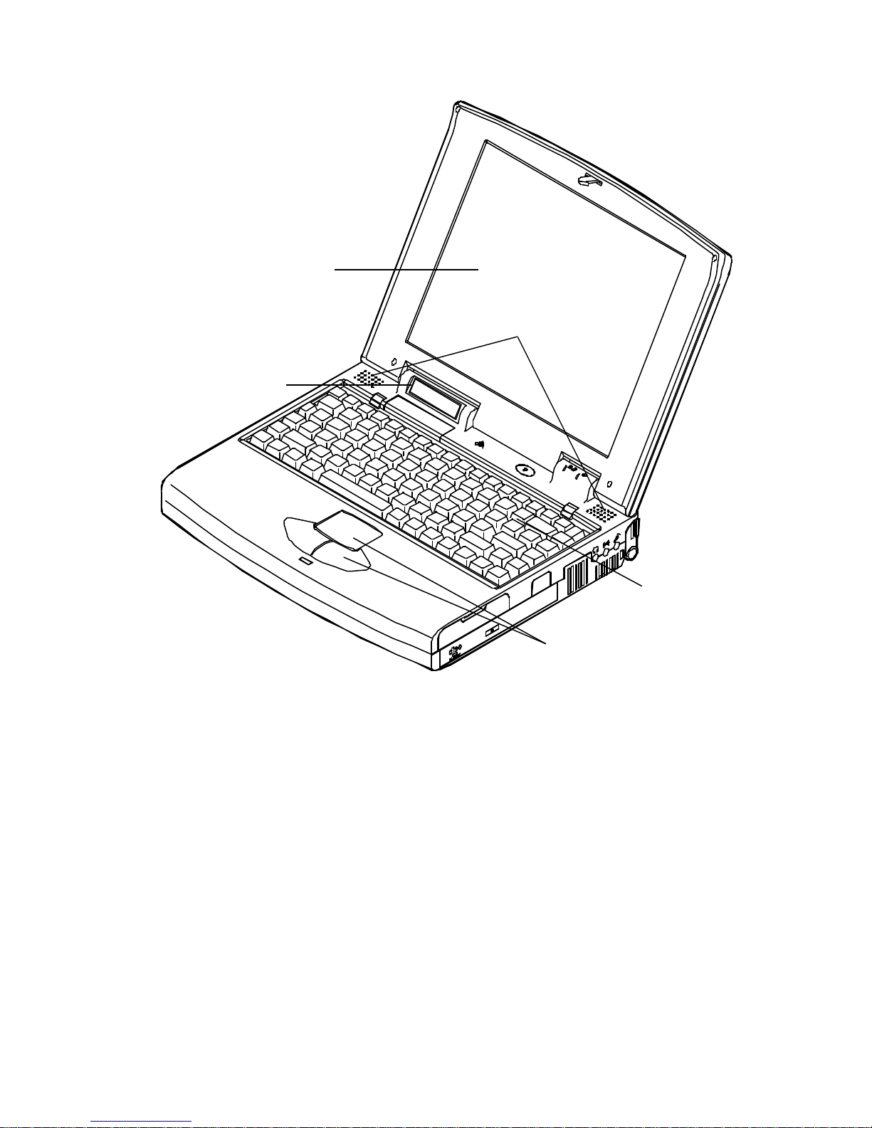
Right View
On the right side panel, you will find the followings:
Right-Side Stand
Slide this stand outward (together with the left-side stand) to adjust the viewing
angle.
Microphone-in Jack
This audio port accepts sound source to record or to playback when externally
connected microphone is used instead of the built-in one.
Line-in Jack
This audio port accepts sound source to record or to playback when the sound
source comes from other device’s audio output than the system’s.
Headphone Jack
This audio port accepts sound source to playback if externally connected
headphone is desired instead of the built-in speakers.
Infrared
The wireless communications capabilities are based on IrDA (Infrared Data
Association) standards for cordless connection between the Notebook Computer
and an IrDA-compliant device.
PC Card Type III Expansion Slot
The Type III PC Card slot is located inside a flip-down panel. It allows you to
conveniently attach numerous accessories to the Notebook Computer. It is
equivalent to two Type II PC Cards slots. The ejection button for the upper slot is
located on the left. The ejection button for the lower slot is on the right.
CD-ROM Drive
The 5.25” IDE CD-ROM drive uses the tray loading mechanism for ease of use.
Press the ejection button to load the tray from the drive unit.
Ventilation
The Notebook features a ventilation to dissipate the system’s operating heat. Do
not block or obstruct it during operation.
8
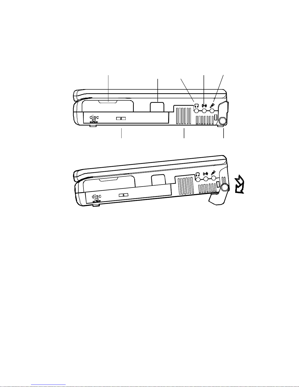
Infrared PC card Type III
CD-ROM drive Ventilation
Microphone-in Line-in Headphone
Right-side stand
9

10
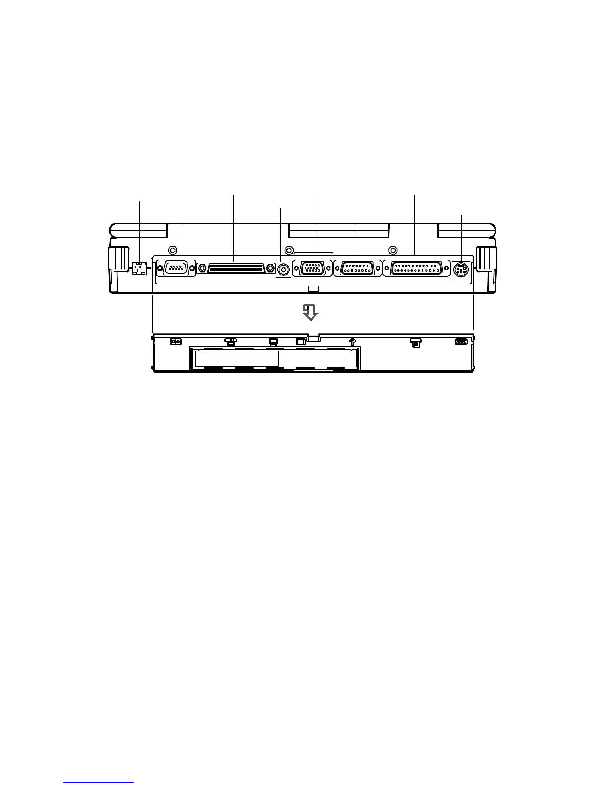
Rear View
The rear panel of the Notebook Computer offers several ports for the electrical connection to
peripheral devices.
DC-in Socket
This socket is where the Notebook Computer’s universal AC/DC power adapter is
connected to the system. To disconnect the power adapter, pull the plug (not the
cord) directly back.
Serial Port
This is a high speed NS16C550 compatible port to connect an external mouse for
example.
Expansion Port
This port is used to connect the proprietary Docking Station. All of the features of
the Docking Station are available through the plug -in process offering the Notebook
Computer access to a desktop system.
RCA Jack
This is an RCA jack to connect a TV set for example.
You may need to select the video standard (NTSC/PAL) for video display.
External Monitor (CRT) Port
This port allows the connection of an external monitor to the system. It uses a 15pin connector and supports super-VGA, and Simultaneous display of LCD and
CRT.
MIDI/Game Port
This port is used to either connect any MIDI device such as a MIDI instrument or
keyboard, or connect an external standard joystick.
Parallel Port
This is a parallel port to connect a printer for example. It supports EPP (Enhanced
Parallel Port) and ECP (Extended Capabilities Port) modes, but required as well is
the use of the connected parallel device’s software driver.
External Keyboard or PS/2 Mouse Port
An external keyboard is able to be connected to the system via this port. So is an
external PS/2 mouse to the system as another pointing device choice.
11
DC-in socket
Serial port
Expansion port
RCA jack
CRT port
MIDI/Game port
Parallel port
PS/2 port

12
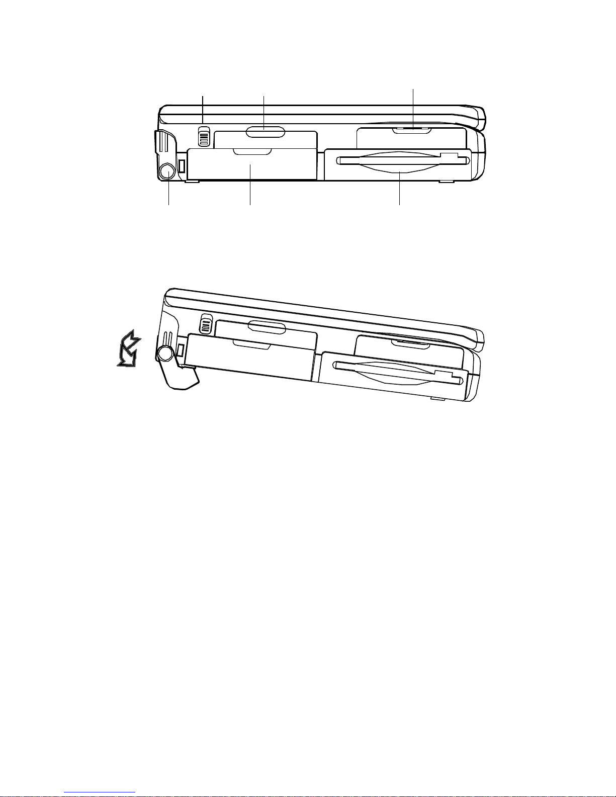
Left View
The left side of the Notebook Computer features the followings:
Left-Side Stand
Slide this stand outward (together with the right-side stand) to adjust the viewing
angle.
Battery Latch
Sliding the battery latch upward will unload the battery pack.
PC Card Type II Slot
The PC Card slot will accommodate a Type II format for system expansion
capability.
2.5” Hard Disk Drive
The system’s 2.5” hard disk features a high capacity for data storage providing
high access time for excellent performance.
3.5” Floppy Disk Drive
This is the location of the Notebook Computer’s 3.5” high density 1.44MB floppy
diskette drive. You may press the button on its top-right side for diskette ejection.
Internal Battery Pack
The Notebook Computer’s internal rechargeable battery pack provides the system
with the power for long run time.
13
Battery latch PC card Type II 2.5” hard disk drive
Left-side stand Internal battery pack 3.5” floppy diskette drive
14
Power
Before using the Notebook Computer, you must supply it power. If this is the first time the
Notebook Computer is operated, you should use the AC power source since the internal battery
pack may have self -discharged during shipment.
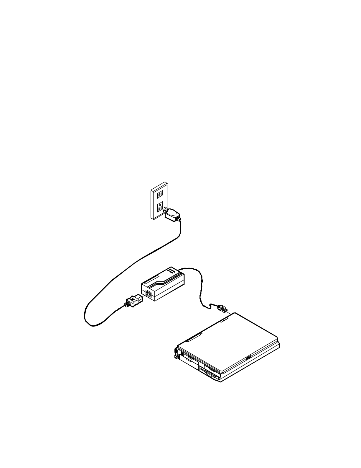
AC Power
The Notebook Computer features a universal, auto-switching power adapter. This adapter is
suitable for use nearly anywhere.
1. Connect the AC power cord to the power adapter.
2. Plug the power adapter to the DC -in socket on the rear panel of the Notebook Computer.
3. Plug the AC power cord into a properly grounded outlet.
15
Internal Battery Power
The Notebook Computer is equipped with an internal, rechargeable battery pack which provides
continuous portable operation.
Proper care is required for optimum performance:
• Do not attempt to disassemble the battery under any circumstances.
• The battery may explode if exposed to fire or high temperatures.
•
Avoid short circuit the battery by the metal terminals (+, -).
16
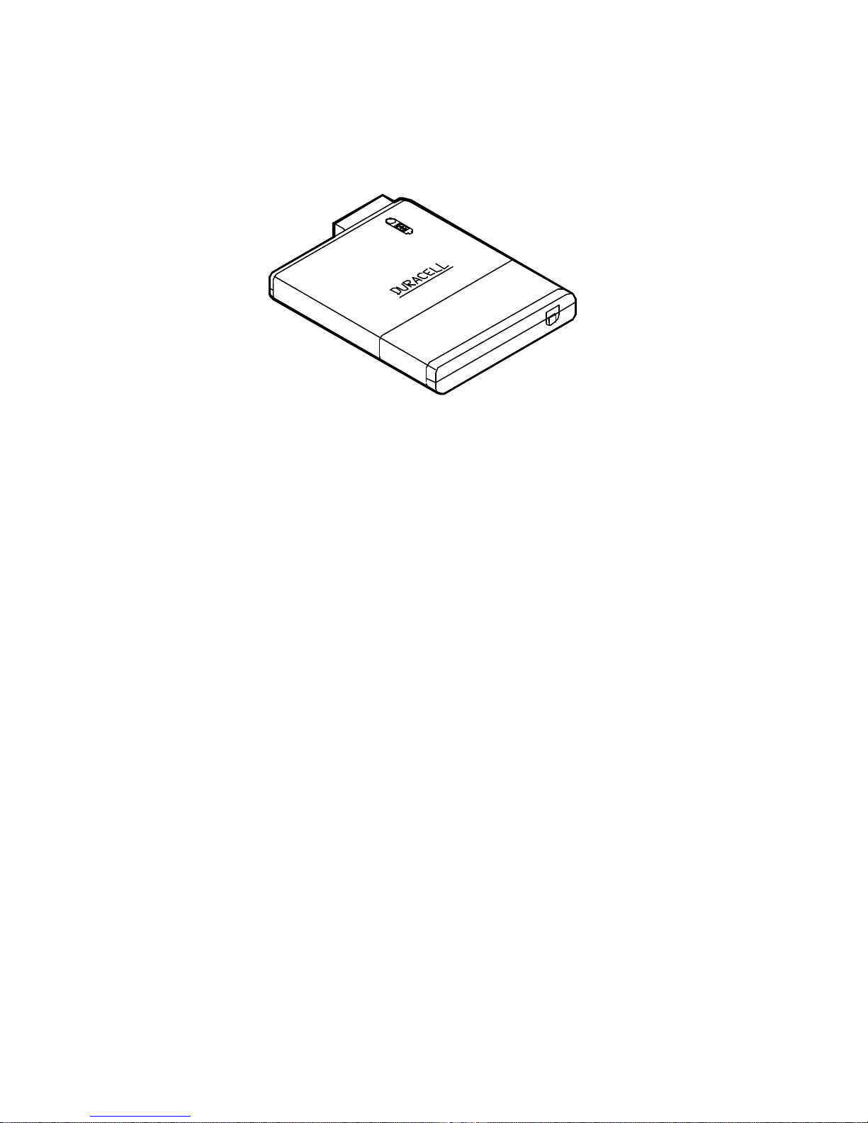
Duracell Smart Battery at Retail
You may replace with Duracell Smart Battery, available at retail outlets around the world, to
accurate indicate a fuel gauge of the predicted available charge for the present state information.
Recharged by AC Power
The system’s battery pack will recharge whenever the system is plugged into the AC power
supply, regardless if the system is being operated or not. Hours may be needed to charge the
battery pack for long service life.
Some instructions should be carefully concerned before you charge the battery pack:
• Upon the very first use, or after a long period of storage, the system might indicate that
charging is complete after just a short time. Simply remove the battery to cool it off
and then repeat the charging procedure at least three times.
• It is recommended to fully discharge the battery before charging to keep memory
effect
from capacity loss.
17
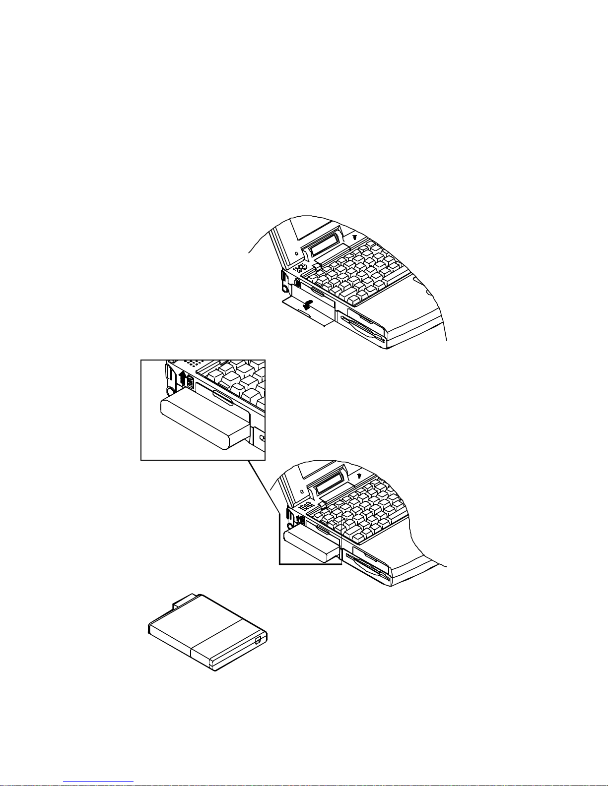
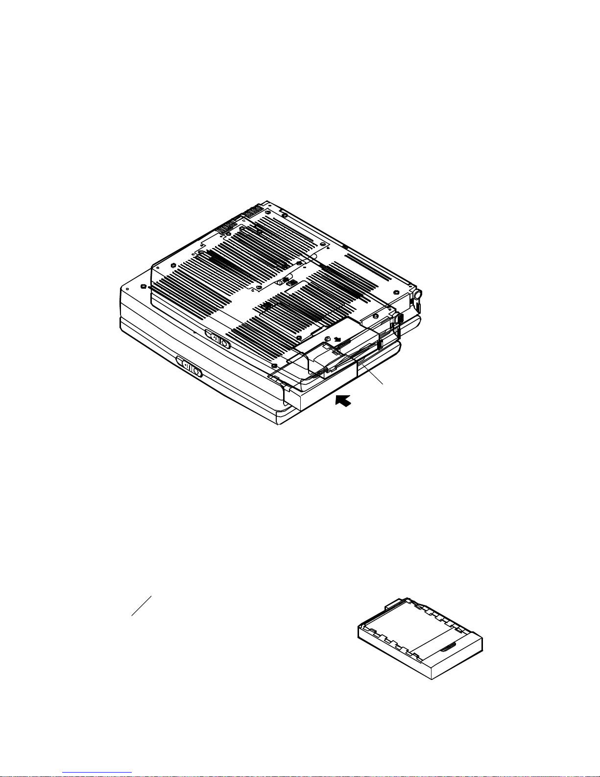
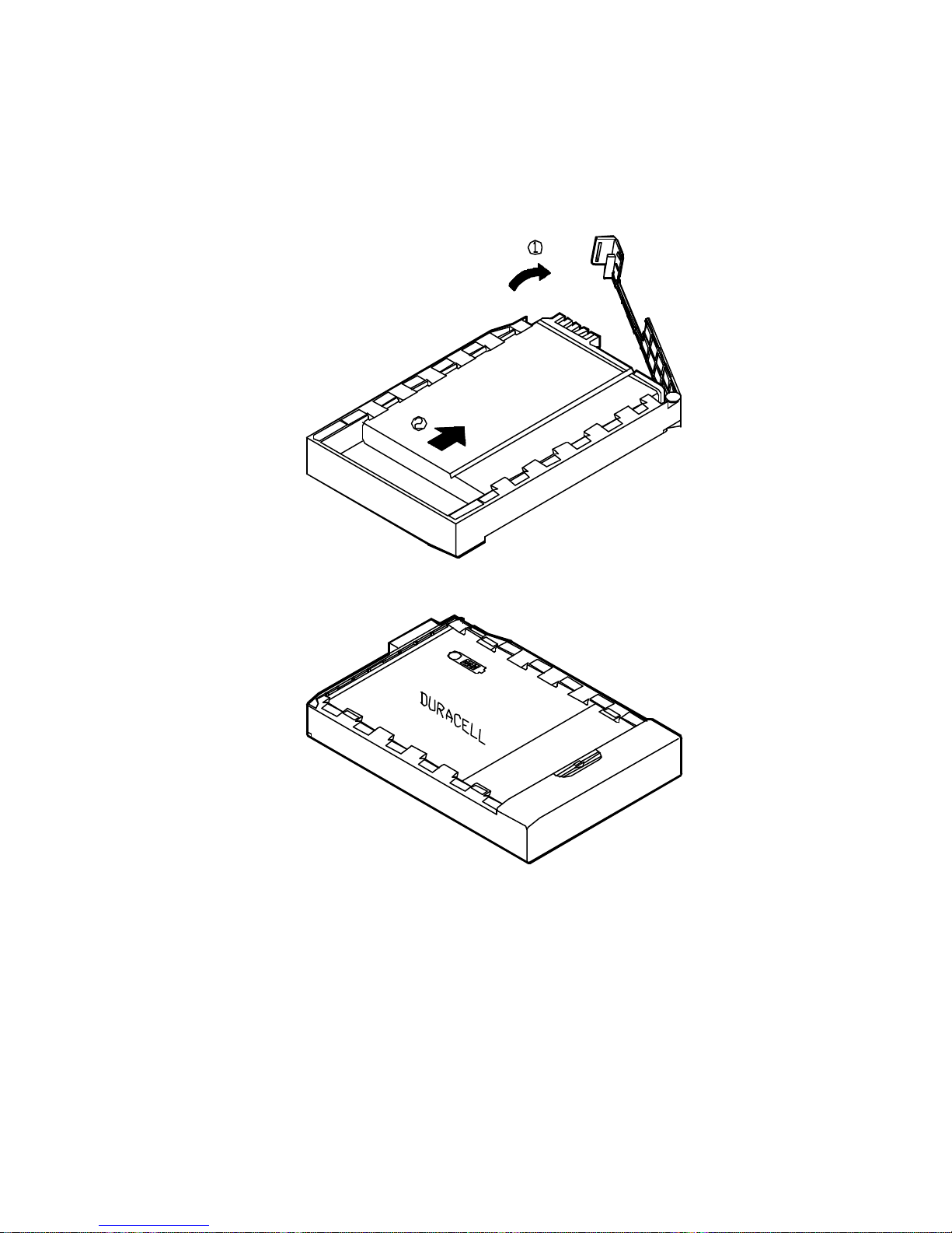
Second Battery Power (Option)
The Second Battery comes designed, in addition to the system’s internal one, to prolong the
battery life for the unit’s portable use.
You may need to replace the floppy disk out of the 3.5” drive bay with the Second Battery pack
for longer power life.
Second battery pack
3.5” floppy disk
18
Duracell Smart Battery at Retail
You may replace with Duracell Smart Battery, available at retail outlets around the world, to
accurate indicate a fuel gauge of the predicted available charge for the present state information.
Recharged by AC Power
The Second battery is charged the same way you do the internal one.
19
Operation
Hardware Configuration
Disconnect all power supply both AC adapter and battery pack before work on any hardware
setting.
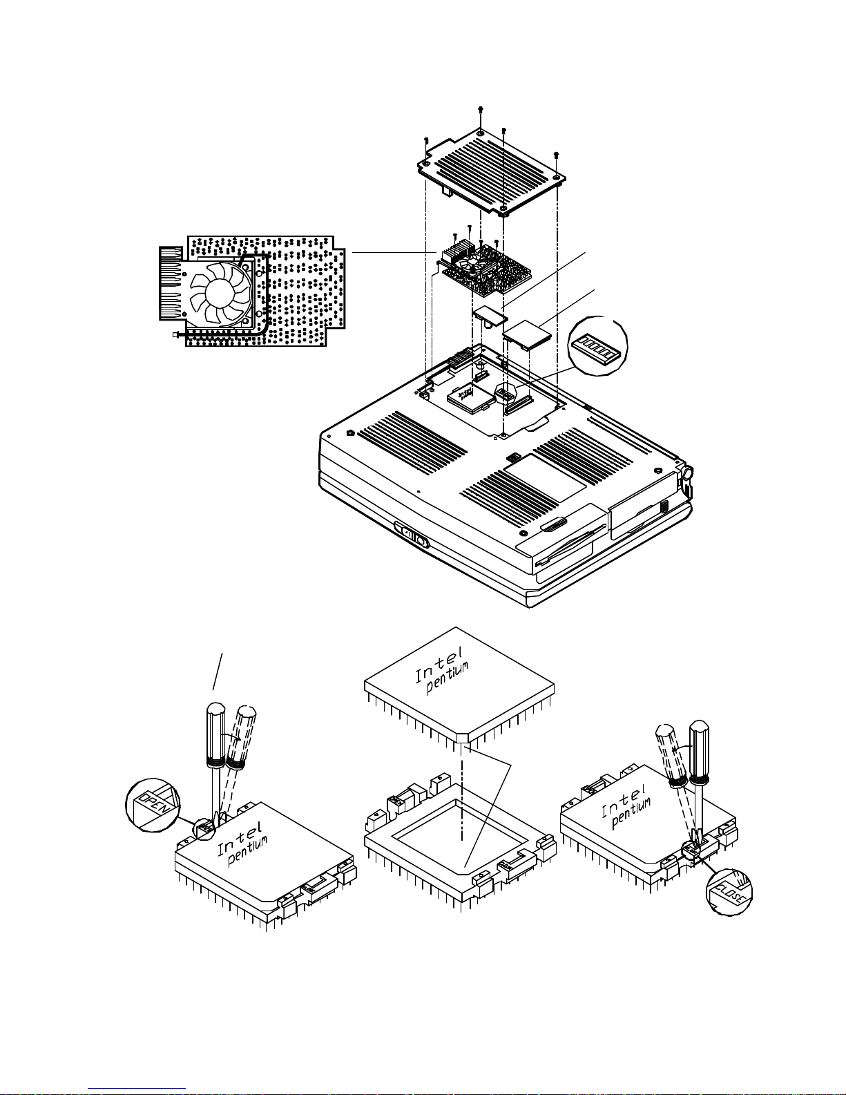
CPU
The system is upgradeable with a wide range of speed and voltages of the Intel Pentium
processors, providing user with a Zero-Insertion-Force (ZIF) socket to facilitate removal of the
Pentium processor and installation of an upgraded one.
ZIF Socket
1. Lever along with a slotted screwdriver on the ZIF socket’s OPEN position to unlock the
CPU.
2. Aligning the CPU’s index corner with the socket’s to install the CPU into place.
3. Lever along with a slotted screwdriver on the ZIF socket’s CLOSE position to lock the CPU.
Heat Sink & Fan for CPU
1. Use a sharp-less tool to arrange the cable clockwise along the fan but outside the two
screws.
2. Attach to the installed CPU.
3. Connect the properly seated cable to the mainboard for CPU temperature dissipation.
4. Reinstall the four screws surrounding the fan to fasten the heat sink. (Work at each other’s
opposite angle is recommended for equal attachment.)
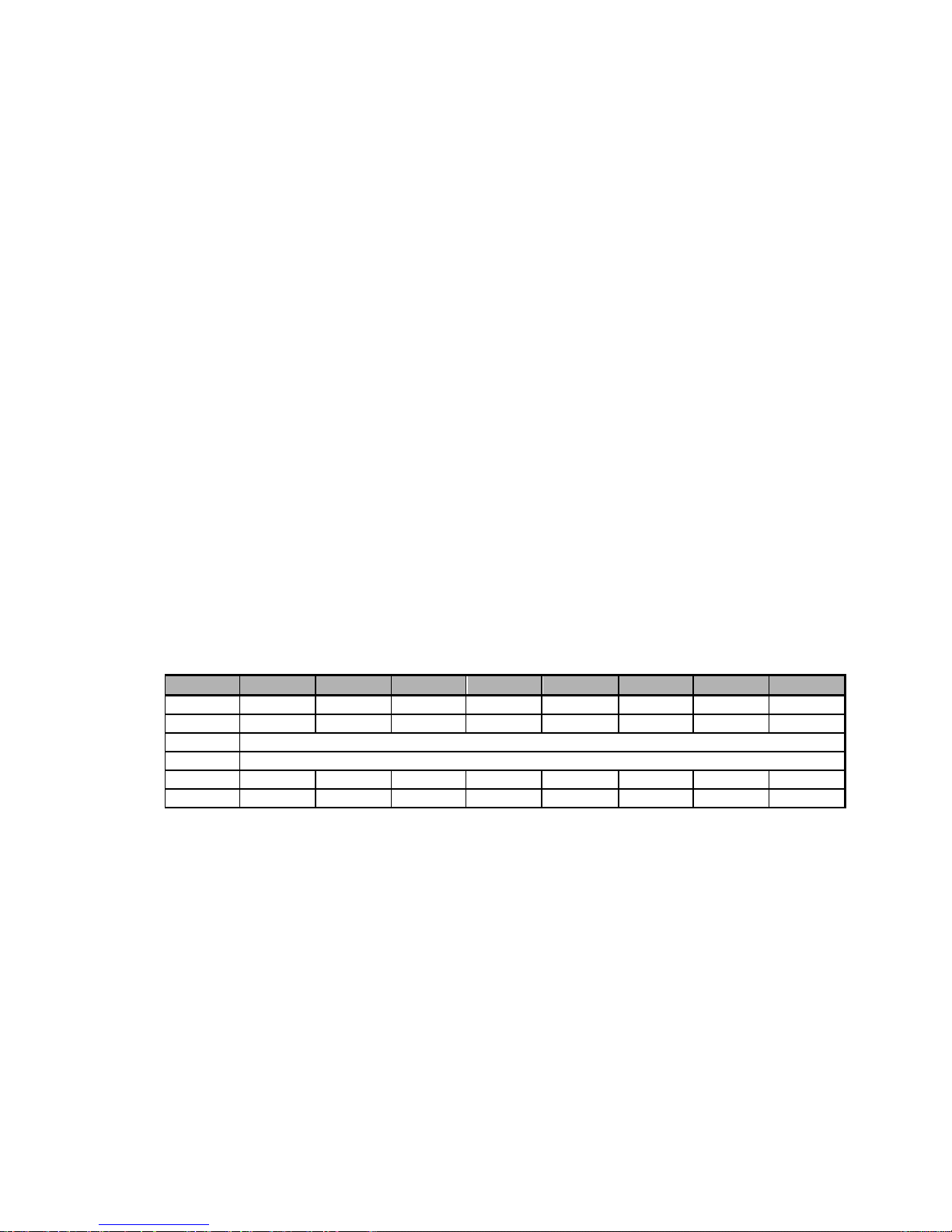
Speed of CPU
Pentium 75 MHz 90 MHz 100 MHz 120 MHz 133 MHz 150 MHz 166 MHz 200 MHz
S2-1 Off On Off On Off On Off Off
S2-2 On Off Off Off Off Off Off Off
S2-3 Off
S2-4 Off
S2-5 Off Off Off On On On On Off
S2-6 Off Off Off Off Off On On On
Power of CPU
The power of CPU varies with the CPU’s voltage supply. You may need to attach the proper
circuit board of Power of CPU responding to the CPU you install.
• 3.3 volts
• 3.1 volts
• 2.9 volts
MPEG Accelerator Card (Option)
The MPEG Accelerator Card is optional for multimedia use of the system to playback a
variety of video formats.
Detailed information is available from the dealer near you upon request.
20
Heat sink & fan for CPU
Power of CPU
MPEG Card (option)
S2
Slotted screwdriver
Index corner
1. Unlock the CPU. 2. Install an upgraded CPU. 3. Lock the CPU.
21
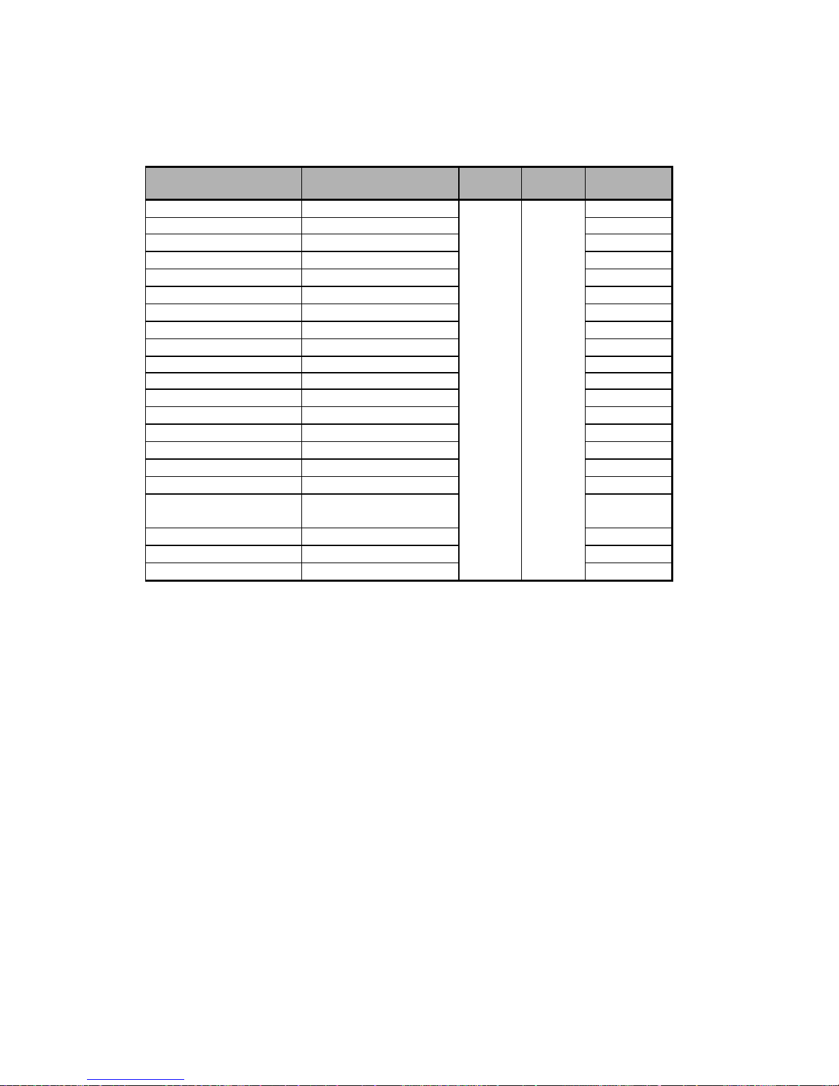
RAM Configuration
The system features an expandable Dynamic RAM in small outline 144 -pin DIMM (Dual In-line
Memory Module) package.
Bank 0 (64 bit) Bank 1 (64 bit) Power
Voltage
(1Mx16)x4 None
None (1Mx16)x4
(1MX16)X4 (1Mx16)x4
(1MX16)X8 None
None (1MX16)X8
(2MX8)X8 None
None (2MX8)X8
(1MX16)X8 (1Mx16)x4
(1MX16)X4 (1MX16)X8
(1MX16)X8 (1MX16)X8
(4MX4)X16 None 5V 70ns 32MB
None (4Mx4)x16
(2MX8)X8 (2MX8)X8
(2MX8)X8 (1MX16)X8
(1MX16)X8 (2MX8)X8
(4Mx4)x16 (1MX16)X4
(1Mx16)x4 (4Mx4)x16
(4Mx4)x16 + (1Mx16)x4 None
(4Mx4)x16 + (1Mx16)x4 (1MX16)X4
(4Mx4)x16 + (1Mx16)x4 (1MX16)X8
(4Mx4)x16 (4Mx4)x16
(4Mx4)x16 + (1Mx16)x4 (4Mx4)x16
Access
Time
RAM Size
8MB
8MB
16MB
16MB
16MB
16MB
16MB
24MB
24MB
32MB
32MB
32MB
32MB
32MB
40MB
40MB
40MB
48MB
56MB
64MB
72MB
22
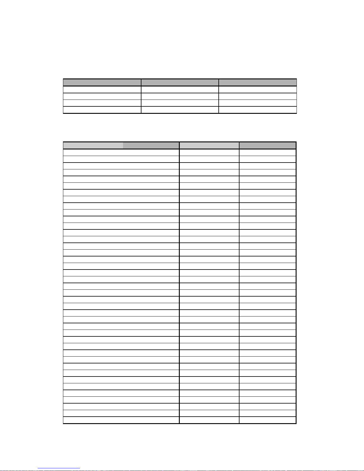
TV-Output
Select the TV standard for video output if a TV set is connected for Games or MPEG playback,
for example. The system display will improve video quality for screen flicker caused by an
interlaced TV monitor.
NTSC PAL
S1-1 On Off
S1-2 Off On
S1-3 On Off
S1-4 Off On
Provided herein is the international TV system for reference. Any discrepancy should be subject
to the local TV standard.
Country TV System Country TV System
Afghanistan PAL Liberia PAL
Algeria PAL Madeira PAL
Argentina PAL Malaysia PAL
Australia PAL Malta PAL
Austria PAL Mexico NTSC
Bahamas NTSC Netherlands PAL
Bahrain PAL Neth. Antilles NTSC
Barbados NTSC New Zealand PAL
Belgium PAL Nicaragua NTSC
Bermuda NTSC Nigeria PAL
Bolivia NTSC Norway PAL
Brazil PAL Oman PAL
Brunei PAL Pakistan PAL
Burma NTSC Panama NTSC
Canada NTSC Paraguay PAL
Canary PAL Peru NTSC
Chile NTSC Philippines NTSC
China PAL Portugal PAL
Colombia NTSC Puerto Rico NTSC
Costa Rica NTSC Qatar PAL
Cuba NTSC Sabah/Sarawak PAL
Cyprus PAL St. Kitts NTSC
Denmark PAL Samoa NTSC
Dominican Republic NTSC Sierra Leone PAL
Ecuador NTSC Singapore PAL
EL Salvador NTSC South Africa PAL
Equatorial Guinea PAL Spain PAL
Finland PAL Sri Lanka PAL
Germany PAL Surinam NTSC
Ghana PAL Swaziland PAL
Gibraltar PAL Sweden PAL
Guatemala NTSC Switzerland PAL
Haiti NTSC Taiwan NTSC
Honduras NTSC Tanzania PAL
Hong Kong PAL Thailand PAL
Iceland PAL Uganda PAL
Indonesia PAL United Kingdom PAL
Ireland PAL USA NTSC
Israel PAL Venezuela NTSC
Italy PAL Vietnam NTSC
Jordan PAL Yemen PAL

23
Kenya PAL Yugoslavia PAL
Korea South NTSC Zambia PAL
Kuwait PAL
 Loading...