

EUROCOM 4200, 4200M, 4600 Service Manual


Preface
I
Preface
Notebook Computer
4200/4200M/4600
Service Manual

Preface
II
Preface
Notice
The company reserves the right to revis e this publication or to change its contents without notice. Information contained
herein is for refere nce only and do es not constitute a commi tment on the part of the manufac turer or any s ubsequent vendor. They assume no responsibility or liability for any errors or inaccuracies that may appear in this publication nor are
they in anyway responsible for any loss or damage resulting from the use (or misuse) of this publication.
This publication and any accompanying software may not, in whole or in part, be reproduced, translated, transmitted or
reduced to any machine readable form without prior consent from the vendor, ma nufacturer or cr eator s of this publication, except for copies kept by the user for backup purposes.
Brand and product names mentioned in this publication may or may not be copyrights and/or registered trademarks of
their respective companies. They are mentioned for identification purposes only and are not intended as an endorsement
of that product or its manufacturer.
Version 1.0
December 2001
Trademarks
Intel® and Pentium® are registered trademarks of Intel Corporation.
Windows
®
is a registered trademark of Microsoft Corporation.
Other brand and product names are trademarks and./or registered trademarks of their respective companies.

Preface
III
Preface
About this Man ua l
This manual is intended for service personnel who have completed sufficient training to undertake the maintenance and
inspection of personal computers.
It is organized to allow you to look up basic information for servicing and/or upgrading components of the Notebook PC.
The following information is included:
Chapter 1, Introduction, provides general information about the location of system elements and their specifications.
Chapter 2, Disassembly, provides step-by-step instructions for disassembling parts and subsystems and how to upgrade
elements of the system.
Appendix A, Part Lists
Appendix B, Switches and Jumpers
Related Documents
You may also need to consult the following manual for additional information:
User’s Manual on CD
This describes the notebook PC’s features and the procedures for operating the computer and its ROM-based setup program. It also describes the installation and operation of the utility programs provided with the notebook PC.

Preface
IV
Preface

Preface
I
Preface
Contents
Introduction ...........................................................1-1
Overview ............. ............ .............. ............. .............. ............ .............. ............ ..... 1-1
System Specifications ......................................................................................... 1-2
Processor ....................... ........................................................... ........................... 1-2
Core Logic ........................................................................................................... 1-2
Memory ........... .......... ............ .......... ............. .......... ............ .......... ............ .......... . 1-2
BIOS .... .... .. .... .. .... .. .... .. .... .. .... .. .... .. .... ... .... .. .... .. .... .. .... .. .... .. .. .... .. .... .. .... .. .... .. .... .. . 1-2
LCD ..... ...... ........ ...... ........ ...... ........ ....... ........ ...... ...... ........ ...... ........ ...... ........ ...... . 1-2
Display ................................................................................................................ 1-3
Audio ... ...... ........ ...... ........ ...... ........ ....... ........ ...... ...... ........ ...... ........ ...... ........ ...... . 1-3
Storage ......................................... ........................................... ............................. 1-3
PC Card Sockets .................................................................................................. 1-3
Keyboard ........................................................................ ..................................... 1-3
Interfa c e ......... ........................................... .................................. ......................... 1-4
Communic ation .. ......... ........ .......... ......... .......... ........ .......... ........ .......... ........ ....... 1-4
Power Mana g ement ........................... ................................... ............................... 1-5
Power ........................................... ........................................... ............................. 1-5
Indicator .............................................................................................................. 1-5
EMC & Safety ..................................................................................................... 1-5
S/W Certi fi cate .................................. ........................... .................................. ..... 1-5
Environm ental Spec ......................................... .................................. ................. 1-5
Dimensi ons .. .. .... .. .... .. .... .. .... .. .... .. .... .. ..... .. .... .. .... .. .... .. .... .. .... .. .... .. .... .. .... .. .... .. .... . 1-5
Weight ........... .......... ............ .......... ............. .......... ............ .......... ............ .......... ... 1-6
Optional ....... ...... ........ ...... ........ ...... ......... ...... ........ ...... ........ ...... ........ ...... ...... ....... 1-6
External Locator - Top View .............................................................................. 1-7
External Loc ator - Left & Right Si d e Views ................ .......... .................... ........1-8
External Locator - Right Side & Bottom Views ................................................. 1-9
Mainboard Overview - Top .......................................................................... ..... 1-10
Key Parts .......................................................................................................... 1-10

Preface
II
Preface
Mainboard Overview - Bottom .............................................................. ........... 1-11
Key Parts ........................................................................................................... 1-11
Mainboard Overview - Top .......................................................................... ..... 1-12
Cable Con n ec t o rs and Switche s ...... ........................... .................................. ..... 1-12
Mainboard Overview - Bottom .............................................................. ........... 1-13
Cable Conn e c t o rs and Switche s ...... ................... .......................... ..................... 1-1 3
Disassembly ............................................................2-1
Overview ............. ............ .............. ............. .............. ............ .............. ............ ..... 2-1
Maintenance Tools .............................................................................................. 2-2
Connect ions . ...... .... ...... .... ...... .... ...... ..... ...... .... ...... .... ...... .... ...... .... ...... .... ...... .... ... 2-2
Maintenance Precautions .................................................................................... 2-3
Cleaning ...............................................................................................................2-3
Disassembly Steps ............................................................................................... 2-4
Remove the Battery ............................................................................................. 2-9
Remove the Hard Disk Drive Assembly ........................................................... 2-10
Remove The Keyboard ..................................................................................... 2-11
Removing The System Memory ....................................................................... 2-12
Remove the CD-Device .................................................................................... 2-13
Remove the CPU ............................................................................................... 2-14
Remove the Modem .......................................................................................... 2-15
Remove the Top Case and LCD ........................................................................ 2-16
Remove the Inverter .......................................................................................... 2-18
Remove the Floppy Disk Drive Assembly ........................................................ 2-19
Remove the Battery Bracket ............................................................................ 2-19
Remove the Bottom Case and Audio Board ..................................................... 2-20
Remove the Fan Unit ........................................................................................ 2-21
Remove the PCMCIA assembly ....................................................................... 2-21
Remove the Power Board .................................................................................. 2-22
Part Lists ...............................................................A-1
Part List Ill u stration Lo c ation ......... ................................... .................................A-2

Preface
III
Preface
Top Assembly (4200) .........................................................................................A-3
Top Assembly (4200 - 15”) ................................................................................A-4
Bottom Assembly (4200) ....................................................................................A-5
LCD 14” (4200) ..................................................................................................A-6
LCD 15” (4200) ..................................................................................................A-7
Battery (4200) .....................................................................................................A-8
CD-ROM Drive (4200) .......................................................................................A-9
DVD-ROM Drive (4200) ......................................... ........ ........ .......... ........ .......A-10
CD-RW Drive (4200) .......................................................................................A-11
Combo Drive (4200) .........................................................................................A-12
Top Assembly (4200M) ....................................................................................A-13
Top Assembly (4200M - 15”) ...........................................................................A-14
Bottom Assembly (4200M) ..............................................................................A-15
LCD 14” (4200M) .............................................................................................A-16
LCD 15” (4200M) .............................................................................................A-17
Battery (4200M) ................................................................................................A-18
CD-ROM Drive (4200M) .................................................................................A-19
DVD-ROM Drive (4200M) ........ ................. ........ ........ ........ .......... ........ ........ ...A-20
CD-RW Drive (4200M) ....................................................................................A-21
Combo Drive (4200M) .....................................................................................A-22
Top Assembly (4600) .......................................................................................A-23
Top Assembly (4600 15”) .................................................................................A-24
Bottom Assembly (4600) ..................................................................................A-25
LCD 14” (4600) ................................................................................................A-26
LCD 15” (4600) ................................................................................................A-27
Battery (4600) ...................................................................................................A-28
CD-ROM Drive (4600) .....................................................................................A-29
DVD-ROM Drive (4600) ......................................... ........ ........ .......... ........ .......A-30
CD-RW Drive (4600) .......................................................................................A-31
Combo Drive - KME (4600) ........................................................................ .....A-32
Combo Drive - Toshiba (4600) ...................................................................... ...A-33
Hard Disk Drive (4200, 4200M & 4600) ..........................................................A-34

Preface
IV
Preface
Floppy Disk Drive (4200, 4200M & 4600) ......................................................A-35
Schematic Diagrams ..............................................B-1
Mainboard ...........................................................................................................B-1
Inverte r ............ ............ .............. ............. .............. ............ .............. ............ .......B-2 9
Power Board .................................... ........................... .................................. .....B-30
Updating the FLASH ROM BIOS......................C- 1

Introduction
Overview 1 - 1
1.Introduction
1: Introduction
Overview
This manual covers the information you need to service or upgrade the 4200/4200M/4600 Notebook Computer. Information about operating the computer (e.g. getting started, and the Setup utility) is in the User’s Manual. Information
about drivers (e.g. VGA & audio) is also found in User’s Manual. That manual is shipped with the computer.
Operating systems (e.g. DOS, Windows 9x, Windows NT 4.0, Windows 2000, Windows XP, OS/2 Warp, UN IX, etc.) have
their own manuals as do application software (e.g. word processing and database programs). If you have questions about
those programs, you should consult those manuals.
The 4200/4200M/4600 notebook is designed to be upgradeable. See “Disassembly” on page 2 - 1 for a detailed description of the upgrade procedures for each specific component. Please note the warning and safety information indicated by
the “” symbol.
The balance of this chapter reviews the computer’s technical specifications and features.

Introduction
1 - 2 System Specifications
1.Introduction
System Specifications
Processor
•Intel® Mobile Pentium III-M 866 ~ 933MHz - 1.00 ~ 1.26 GHz
L2 Cache 512KB
•Intel® Mobile Celeron 733 ~ 933MHz
L2 Cache 256KB
• Supporting µFC-PGA Package
0.13 Micron (Tualatin Process Technology)
Core Logi c
• Intel
®
830MP “Almador-M” :
MCH= FW82830MP
ICH= MFW82801 (ICH3)
Memory
• Two SODIMM sockets
Supporting PC-133/PC-100 SDRAM
Expandable memory up to 1GB
64/128/256/512MB SO-DIMM modules supported
BIOS
• Phoenix BIOS
One 512KB Flash ROM
LCD
• 14.1” TFT XGA 1024x768, or 15.0” TFT SXGA+ 1400x1050

Introduction
System Specificati ons 1 - 3
1.Introduction
Display
• ATI M6-P Integ rated AGP 4X
• Integrated 128-bit 2D / 3D Graphics Accelerator
Advanced HW Acceleration for DVD Playback (Motion Compensation engine and IDCT)
Fully DirectX 8 Compliant Graphics Engine
• External memory up to 32MB or 64MB of DDR SGRAM on board
• Supports dual-view Display Monitor
Audio
• AC’97 ver 2.2 Compliant Interface
3D stereo enhanced sound system
Compatible Sound-Blaster PRO
1 * SPDIF Digital output (5.1 CH) for DVD content
1* built-in microphone and 1* Headphone out
2 * speakers built-in
Storage
• 3.5” 3-mode FDD
• 2.5” 9.5 mm (h) HDD Easy changeable
• One Bay for optional CD-ROM (24X speed) 12.7mmH, OR 8X DVD-ROM (12.7mm), OR CD-RW, OR Combo
• Supports Master mode IDE, PIO mode 4 / ATA-33/66/100 (Ultra DMA)
PC Card Sockets
• PCMCIA 3.3V/5V/12V sockets, type II *2 or type III *1
• Supports Two CardBus slots (No Zoomed Video support available)
Keyboard
• Win key, Multi-Language

Introduction
1 - 4 System Specifications
1.Introduction
Interface
• Built-in Touch pad (Scrolling Key functionality integrated)
• Four USB ports
• One IEEE 1394 port (Mini)
• One S-V ideo jack for TV output
• One parallel port (LPT1), support ECP / EPP
• Infrared file transfer, IrDA 1.1 FIR/SIR/ ASKIR
• External CR T monitor
• One PS/2 port support mouse or keyboard
• One headphone jack
• One microphone jack
• One SPDIF jack
• One RJ-11 jack for Modem
• One RJ-45 jack for LAN
• DC-in jack
• Built-in 3 instant keys, www, email, DVD Player
• One SONY standard Memory Stick
• One PANASONIC SD Memory
Communication
• Infrared transfer: 115.2K bps SIR/ 4M bps FIR, 1M operating distance, IrDA 1.1 compliant
• 10/100Mb Ethernet LAN built-in
• 802.11b Wireless LAN (Optional)
• 56K MDC MODEM with V.90 & V.92 compliant

Introduction
System Specificati ons 1 - 5
1.Introduction
Power Manage ment
• Supports ACPI v1.0b
• Supports APM v1.2
• Supports suspend to RAM
• Supports suspend to disk
• Battery low suspend
• Resume from modem ring
• Resume from LAN ring
Power
• Full Range AC adapter AC in 100~240V, 50~60Hz, DC Output 20V, 3.25A.
• Support one removable Smart Li-Ion Battery 80W
Indicator
• LED indicator (HDD, Power on/ AC-In/SUSPEND, Battery Charging/Battery full, E-mail, Num Lock, Caps Lock,
Scroll Lock)
EMC & Safety
• FCC Class B, CE, VCCI, C-TICK, BSMI, UL, CUL, TUV, CB
S/W Certificate
• MICROSOFT WHQL and WINKEY Logo, MACROVISION
Environmental Spec
• Temperature Relative Humidity
• Operating: 5° C ~ 35°C Operating: 20% ~ 80%
• Non-Operating: -20°C ~ 60°C Non-Operating: 10% ~ 90%
Dimensions
• 312 (w) x272.7(d) x37.5 (h) mm w/14.1” LCD

Introduction
1 - 6 System Specifications
1.Introduction
Weight
• 2.8kg w/o battery
Optional
• 4201 Lithium-Ion smart battery pack (12cell)
• 4202 DVD-ROM Drive Module 12.7mm (h)
• 4203 CD-RW Drive Module 12.7mm (h)
• 4204 Software DVD Player
• 4205 Software RW Writer
• 4206 802.11b Wireless LAN card
• 2005 Car Adapter
Introduction
External Locator - Top View 1 - 7
1.Introduction
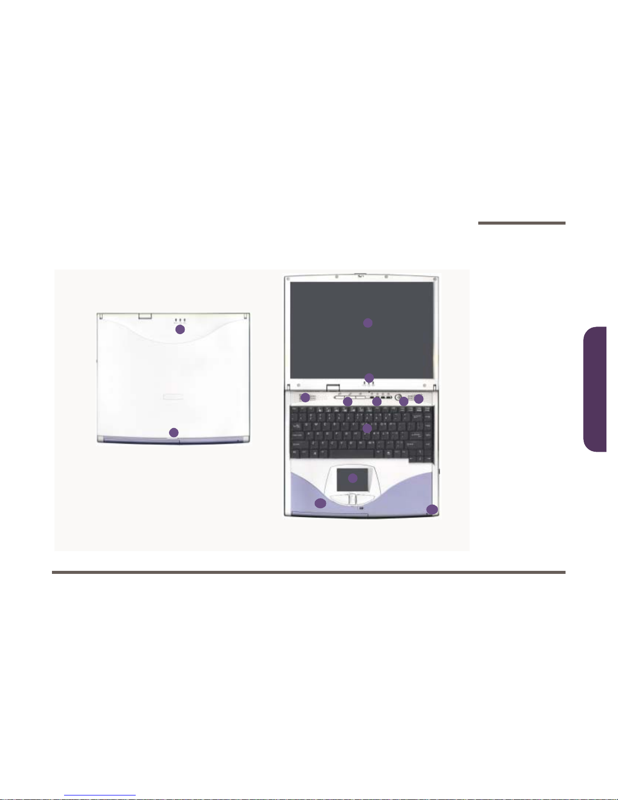
External Locator - Top View
Figure 1 - 1
Top View
4
5 6 7
8
9
10
4
3
2
11
1
2
1. Cover Latch
2. LED Power Indicators
3. LCD Display
4. Speakers
5. Three H ot-Key
buttons
6. LED Status Indicators
7. Power Button
8. Keyboard
9. TouchPad and
Buttons
10.Color Cover
(changeable)
11.Microphone
(built-in)
Introduction
1 - 8 External Locato r - Left & Right Side Views
1.Introduction
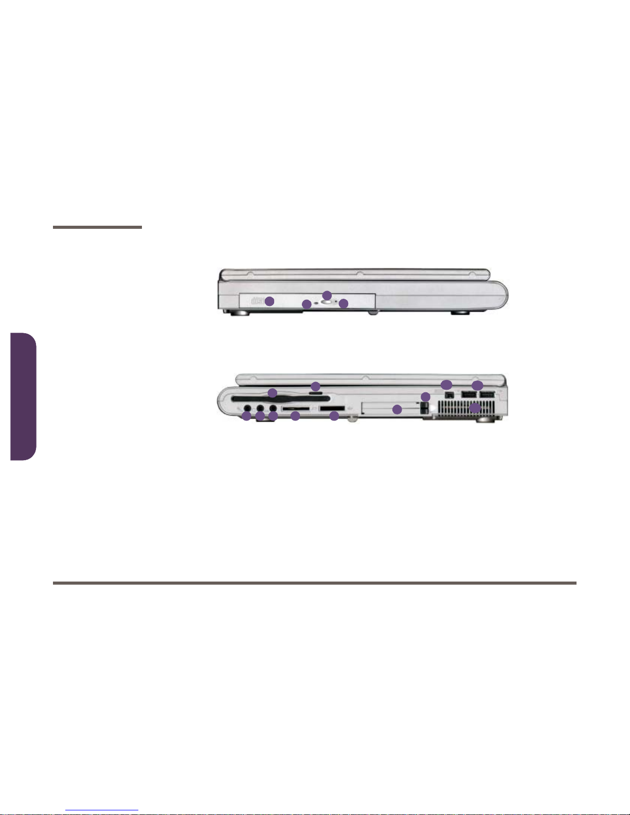
External Locator - Left & Right Side Views
Figure 1 - 2
Left View
Figure 1 - 3
Right View
4
3
1
2
1. CD or DVD Label
Indicator
2. Busy Indicator
3. Open Button
4. Emergency Eject
Hole
1 2 3 4 5
6
7
8
9
10
11
12
1. Microphone-In
Jack
2. Speaker-Out
Jack
3. S/PDIF Port
4. Sony Memory
Stick Port
5. Secure Digital
Port
6. Floppy D is k D riv e
7. Floppy Disk Eject
Switch
8. Dual PC Card
Slots
9. PC Card Socket
Eject Buttons
10.IEE 139 4 Port
11 .Dual USB Po rts
12.Vent
Introduction
External Locator - Right Side & Bottom Views 1 - 9
1.Introduction
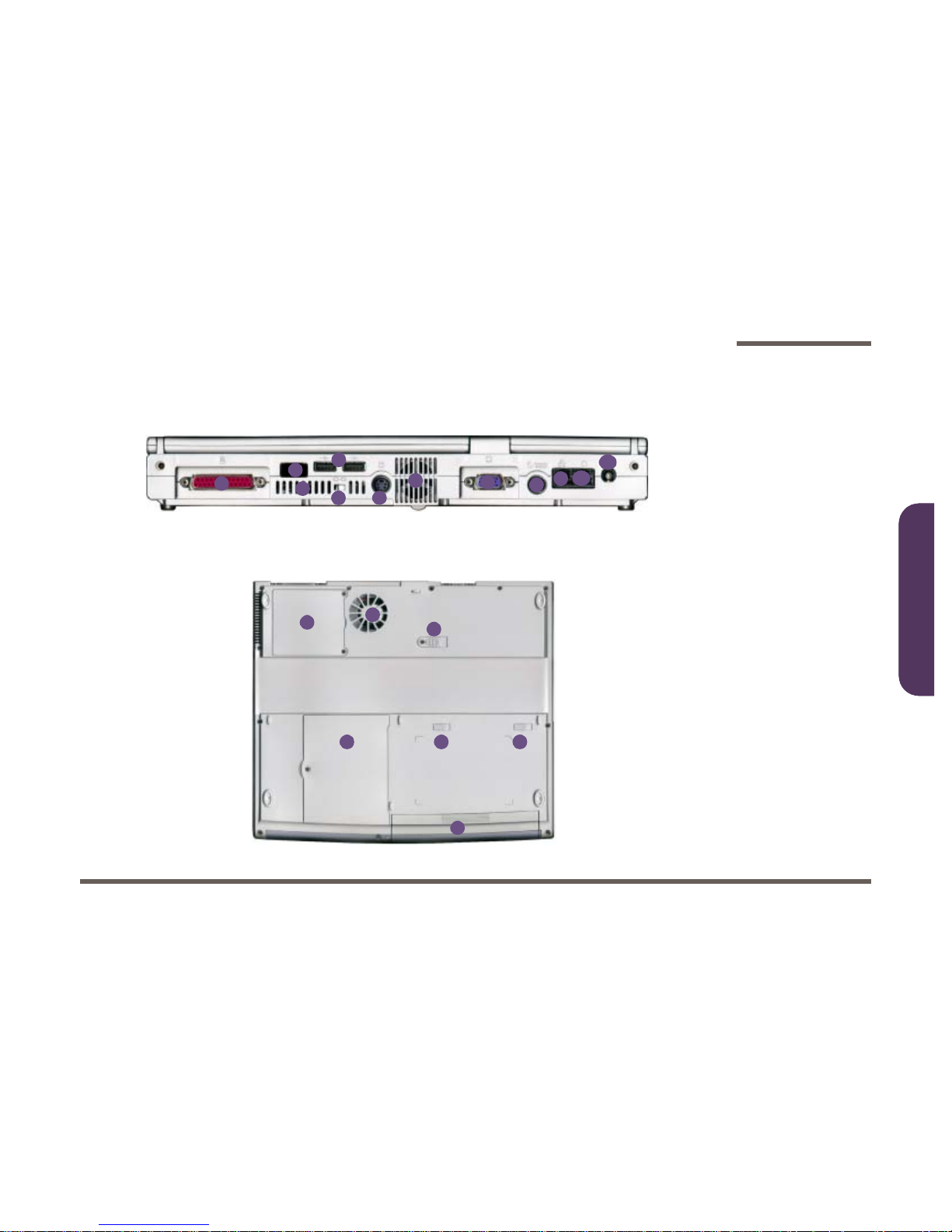
External Locator - Right Side & Bottom Views
1
2
3
4
5
6
3
7
8
9
10
11
Figure 1 - 4
Right Side
1. Parallel Port
2. Infrared Port
3. Vent
4. Security Lock
5. Dual USB Ports
6. S-Video Output
Connector
7. Exrternal Monitor
CRT Port
8. PS/2 Type Port
9. LAN Jack
10.Phone J ac k
11.DC-In Jack
Figure 1 - 5
Bottom View
1. CPU Cover
2. Fan Outlet
3. CD Device
Release Latc h
4. Hard Disk Drive
Cover
5. Battery Release
Latches
6. Battery
2
3
4 5
1
5
6
Introduction
1 - 10 Mainboard Overview - Top
1.Introduction
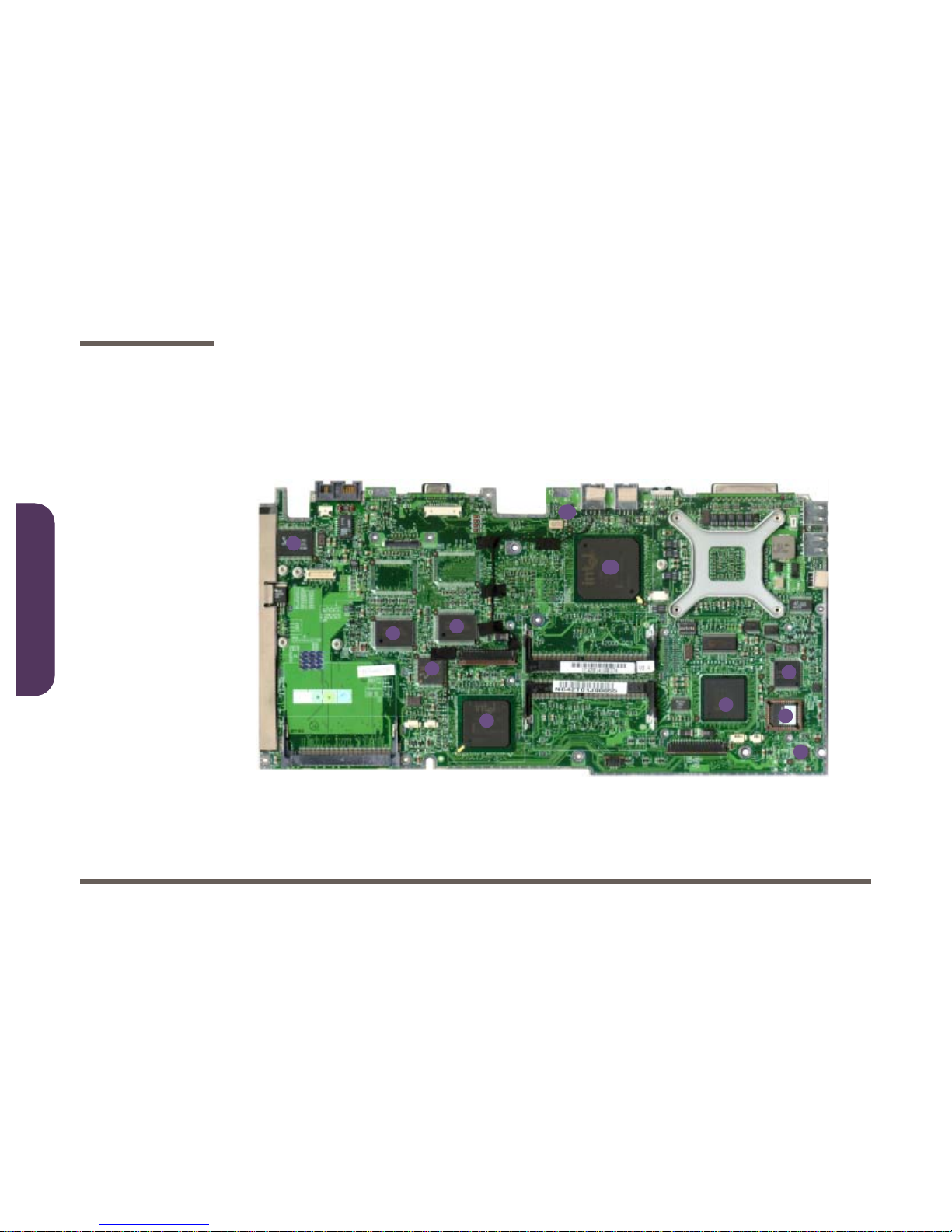
Mainboard Overview - Top
Key Parts
Figure 1 - 6
Mainboard Over-
view - Top
Key Parts
1. Mini-IEEE 1394
controller
2. Flash BIOS ROM
3. Smart I/O
W83518D media
reader contr oller
4. Ricoh Cardbus
PCMCIA cont roller
5. Southbr idge Intel
ICH 3
6. LPC H8 Keyboard contro ller
7. On-b oard video
memory
8. LAN Controller
RTL8139CL
9. Power Button
10.Northbridge Intel
MCH 830MP
1
2
4
5
6
3
7
8
9
7
10
Introduction
Mainboard Overview - Bottom 1 - 11
1.Introduction
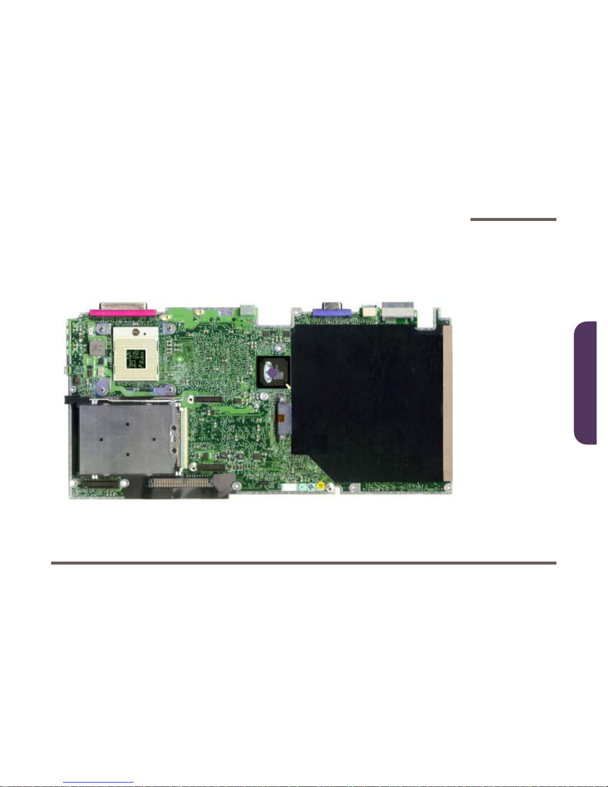
Mainboard Overview - Bottom
Key Parts
Figure 1 - 7
Mainboard Over-
view - Bottom
Key Parts
1. ATI Mobility
Radeon Graphics controlle r
1
Introduction
1 - 12 Mainboard Overview - Top
1.Introduction
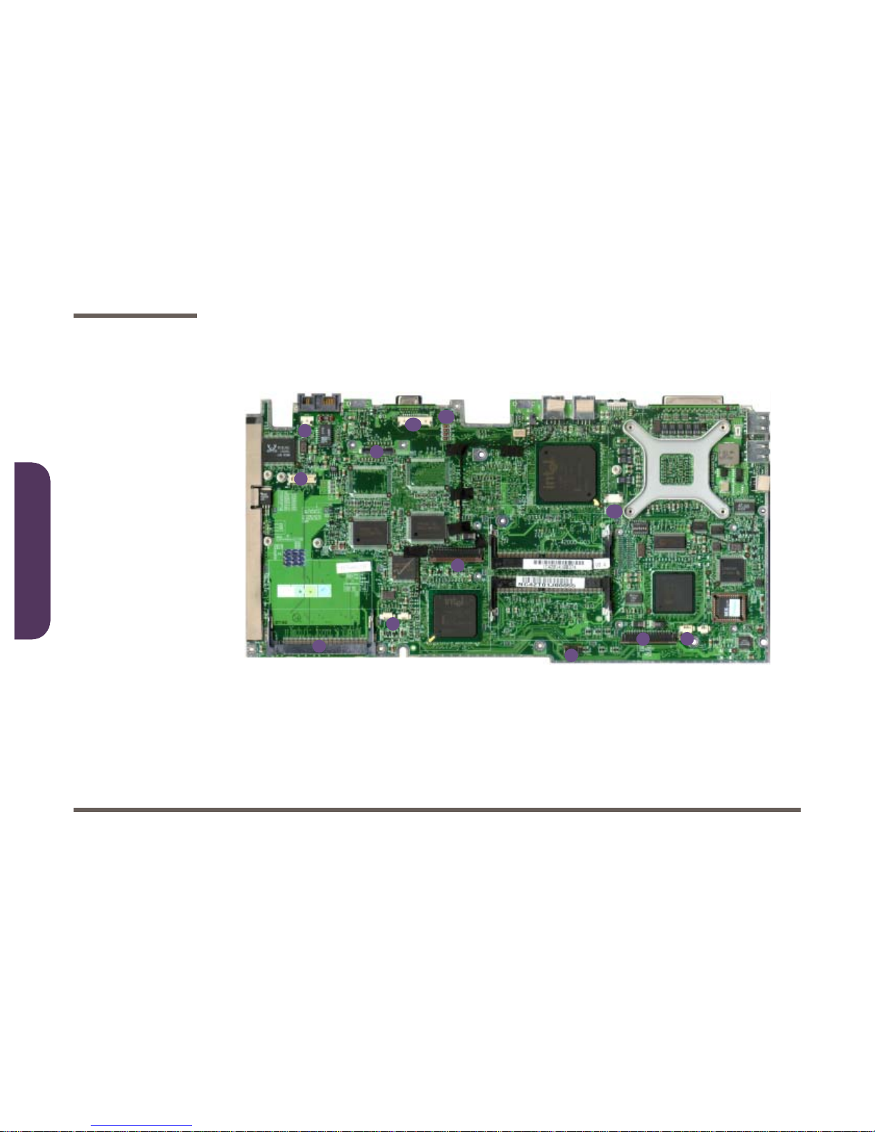
Mainboard Overview - Top
Cable Connectors and Switches
Figure 1 - 8
Mainboard Over-
view - Top
Cable Con n ectors
& Switches
1. Internal speaker
connectors
(JSPK1 & J8PK2
2. FDD c onnector
3. TouchPad connector (JTP1)
4. Keyboard connector (JINTKB1)
5. Batte ry c onnectors (JBAT1 &
CN3)
6. Wireless LAN
socket (CN2)
7. Modem sock et
8. Modem conn ec tor (JModem 1)
9. LCD socket
(JLCD1)
10.Inverter socket
(JINV1)
11.Fan socket
(JFAN1)
12.LED cover connector (JLED 1)
2
5
7
8
10
11
4
6
1
3
9
12
Introduction
Mainboard Overview - Bottom 1 - 13
1.Introduction
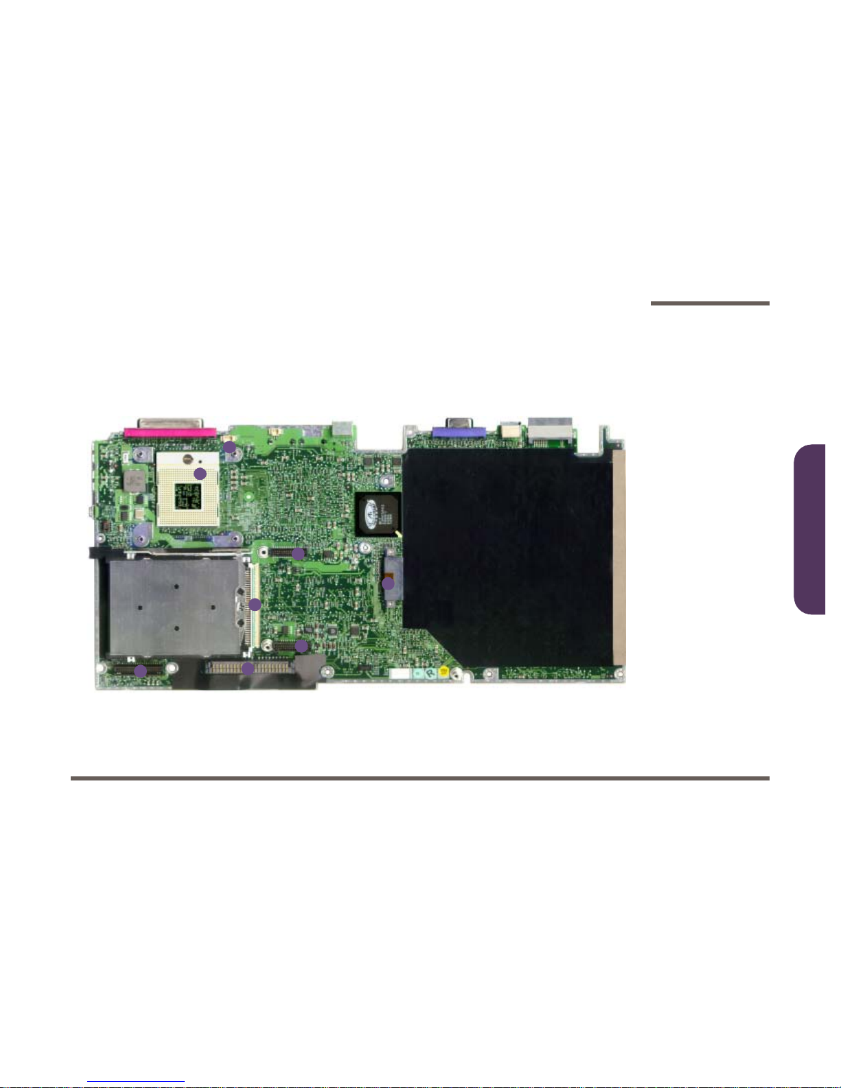
Mainboard Overview - Bottom
Cable Connectors and Switches
Figure 1 - 9
Mainboard Over-
view - Bottom
Cable Con n ectors
& Switches
1. CD device socket
2. Power board
sockets (CN4 &
CN5)
3. HDD Connector
(CON2)
4. Audio board
socket
(JAUDIO1)
5. PCMCIA socket
(SLOT1)
6. CPU Socket (no
CPU installed)
7. Fan Socket
(JFAN2)
1
2
4
5
6
3
2
7

Introduction
1 - 14 Cable Connectors and Switches
1.Introduction

Disassembly
Overview 2 - 1
2.Disassembly
2: Disassembly
Overview
This chapter provides step-by-step instructions for disassembling parts and subsystems. When it comes to reassembly,
reverse the procedures (unless otherwise indicated).
We suggest you completely review any procedure before you take the computer apart.
Procedures such as upgrading/replacing the RAM, CD device and hard disk are included in the Us er’s Manual but are
repeated here for your convenience.
To make the disassembly process easier each section may have a box in the page margin. Information conta ined under
the figure # will give a synopsis of the sequence of procedures involved in the disassembly procedure. A box with a
lists the relevant parts you will have after the disassembly process is complete. Note: The parts listed will be for the disassembly procedure listed ONLY, and not any previous disassembly step(s) required. Refer to the part list for the previous disassembly procedure. The amount of screws you should be left with will be listed here also.
A box with a
5 will provide any possible helpful information. A box with a contains warnings.
An example of these types of boxes are shown in the sidebar.
Component Parts
.
5
Information
.
Warning

Disassembly
2 - 2 Overview
2.Disassembly
NOTE: All disassembly procedures assume that the sys tem is turned OFF, and disconnected from any power supply (the
battery is removed too).
Maintenance Tools
The following tools are recommended when working on the notebook PC:
• M3 Philips-head screwdriver
• M2.5 Philips-head screwdriver (magnetized)*
• M2 Philips-head screwdriver
• Small flat-hea d scre wd ri ver
• Pair of needle-nose pliers
• Anti-static wrist-str ap
Connections
Connections within the computer are one of four types:
Locking collar sockets for ribbon connectors To release these connectors, use a small flat-hea d screwdriver to
gently pry the locking collar away from its base. When replacing the connection, make sure the connector is oriented in the
same way. The pin1 side is usually not indicated.
Pressure sockets for multi-wire connectors To release this connector type, grasp it at its head and gently
rock it from side to side as you pull it out. Do not pull on the
wires themselves. When replacing the connection, do not try to
force it. The socket only fits one way.
Pressure sockets for ribbon connectors To release these connectors, use a small pair of needle-nose pli-
ers to gently lift the connector away from its socket. When replacing the connection, make sure the connector is oriented in
the same way. The pin1 side is usually not indicated.
Board-to-board or multi-pin sockets To separate the boards, gently rock them from side to side as
you pull them apart. If the connection is very tight, use a small
flat-head screwdriver - use just enough force to start.

Disassembly
Overview 2 - 3
2.Disassembly
Maintenance Precautions
The following precautions are a reminder. To avoid personal i njury or damage to the c omputer while performing a removal and/or replacement job, take the following precautions:
1. Don't drop it. Perfo rm y our repairs and/or upgrades on a stable surface. If th e c om puter falls, the ca s e and other
components could be damaged.
2. Don't overheat it. Note the proximity of an y heating elements. Keep the comp ut er out of direct su nlight.
3. Avoid interference. Note the proximity of any high capacity tra ns f ormers, elect ric m ot ors, and other st rong magnetic fields. Th es e c an hinder proper performanc e and damage co mponents and/or data. You should also monitor
the position of ma gnetized tools (i. e. screwdrivers).
4. Keep it dry. This is an electrical appliance. If water or any other liquid gets into it, the computer could be badly damaged.
5. Be care fu l wi th p o wer. Avoid accidental shocks, discharges or explosions.
• Before removing or servicing any part from the computer, turn the computer of f and detach any power supplies.
• When you want to unplug the power cord or any cable/wire, be sure to disconnect it by the plug head. Do not pull on the
wire.
6. Peripherals – Turn off and detach any peripherals.Be ware of static discharge. ICs, such as the CP U and main
support chips, are vulnerable to stati c e lec t ric it y. Before ha ndling any part in the co m puter, discharge any static
electricity ins ide the computer. When handling a printed circuit board , d o not use gloves or o th er m aterials which
allow static electricity buildup . We su ggest that you use an anti-static wr is t st rap instead.
7. Beware of corrosion. As you perform y our job, avoid tou c hing any connec t or leads. Even the cleanest hands produce oils which c an attract corrosiv e elements.
8. Keep your wor k environment clean . Tobacco smoke, dust or other air-born particulate matter is often attracted to
charged surfac es, reducing performance.
9. Keep track of the components. When removing or replacing any part, be careful not to leave small parts, such as
screws, loose inside the computer.
Cleaning
Do not apply cleaner directly to the computer, use a soft clean cloth.
Do not use volatile (petroleum distillates) or abrasive cleaners on any part of the computer.

Disassembly
2 - 4 Disassembly Steps
2.Disassembly
Disassembly Steps
The following table lists the disasse mbly steps, and on which page to find the related information. PLEASE PERFORM
THE DISASSEMBLY STEPS IN THE ORDER INDICATED.
To remove the hard disk drive assembly:
1.Remove the battery page 2 - 9
2.Remove the hard disk drive assembly page 2 - 10
To remove the keyboard:
1.Remove the battery page 2 - 9
2.Remove the keyboard page 2 - 11
To remove the system memory:
1.Remove the battery page 2 - 9
2.Remove the keyboard page 2 - 11
3.Remove the system memory page 2 - 12
To remove the CD Device:
1.Remove the battery page 2 - 9
2.Remove the CD Device page 2 - 13
To remove the CPU:
1.Remove the battery page 2 - 9
2.Remove the CPU page 2 - 14

Disassembly
Disassembly Steps 2 - 5
2.Disassembly
To remove the modem:
1.Remove the battery page 2 - 9
2.Remove the keyboard page 2 - 11
3.Remove the modem page 2 - 15
To remove the Top Case and LCD:
1.Remove the battery page 2 - 9
2.Remove the CD Device page 2 - 13
3.Remove the hard disk drive assembly page 2 - 10
4.Remove the keyboard page 2 - 11
5.Remove the system memory page 2 - 12
6.Remove the CPU page 2 - 14
7.Remove the top case and LCD page 2 - 16
To remove the Inverter:
1.Remove the battery page 2 - 9
2.Remove the CD Device page 2 - 13
3.Remove the hard disk drive assembly page 2 - 10
4.Remove the keyboard page 2 - 11
5.Remove the system memory page 2 - 12
6.Remove the CPU page 2 - 14
7.Remove the top case and LCD page 2 - 16
8.Remove the inverter page 2 - 18
5
Modem Cable
The procedure described here is sufficient to enable the
removal of the modem
module itself.
If the modem cable
also needs to be removed, or a new modem module and cable
inserted, then the top
case must also be removed to access the
cable connector.
See “To remove the
Top Case and LCD:”
on page 2 - 5.

Disassembly
2 - 6 Disassembly Steps
2.Disassembly
To remove the floppy disk drive assembly:
1.Remove the battery page 2 - 9
2.Remove the CD Device page 2 - 13
3.Remove the hard disk drive assembly page 2 - 10
4.Remove the keyboard page 2 - 11
5.Remove the system memory page 2 - 12
6.Remove the CPU page 2 - 14
7.Remove the top case and LCD page 2 - 16
8.Remove the floppy disk drive page 2 - 19
To remove the audio board:
1.Remove the battery page 2 - 9
2.Remove the CD Device page 2 - 13
3.Remove the hard disk drive assembly page 2 - 10
4.Remove the keyboard page 2 - 11
5.Remove the system memory page 2 - 12
6.Remove the CPU page 2 - 14
7.Remove the top case and LCD page 2 - 16
8.Remove the floppy disk drive page 2 - 19
9.Remove the bottom case and audio board page 2 - 20
 Loading...