

EUROCOM 3400 UltraLite, 3420 Ultimate Traveller, 3420-SE Ultimate Traveler, 3420-T2 UltraSlim, 3420 Ultimate Traveler User Manual
Page 1

1
2
3
4
5
6
7
8
i
Page 2

1
2
3
4
5
6
7
8
ii
Preface: legalaties
NOTICE
The company reserves the right to revise this publication or to change its
contents without notice. Information contained herein is for reference
only and does not constitute a commitment on the part of the manufacturer or any subsequent vendor. They assume no responsibility or liability for any errors or inaccuracies that may appear in this publication nor
are they in anyway responsible for any loss or damage resulting from the
use (or misuse) of this publication.
This publication and any accompanying software may not, in whole or in part,
be reproduced, translated, transmitted or reduced to any machine readable form
without prior consent from the vendor, manufacturer or creators of this publication, except for copies kept by the user for backup purposes.
Brand and product names mentioned in this publication may or may not be copyrights and/or registered trademarks of their respective companies. They are mentioned for identification purposes only and are not intended as an endorsement
of that product or its manufacturer.
1st Edition ©March, 2000
TRADEMARKS
This product incorporates copyright protection technology that is protected by method claims of
certain U.S. patents and other intellectual property rights owned by Macrovision Corporation and
other rights owners. Use of this copyright protection technology must be authorized by Macrovision
Corporation, and is intended for home or other limited viewing uses only unless otherwise authorized by Macrovision Corporation. Reverse engineering or disassembly is prohibited.
Intel and Pentium are registered trademarks of Intel Corporation.
MS-DOS, Windows, Windows 95, Windows 98 and Windows NT are registered trademarks of
Microsoft Corporation.
Page 3

1
2
3
4
5
6
7
8
iii
Preface: FCC statement
FEDERAL COMMUNICATIONS COMMISSION
(FCC) STATEMENT
This equipment has been tested and found to comply with the limits for a Class B
digital device, pursuant to Part 15 of the FCC Rules. These limits are designed to
provide reasonable protection against harmful interference in a residential installation. This equipment generates, uses and can radiate radio frequency energy and, if not installed and used in accordance with the instructions, may cause
harmful interference to radio communications. However, there is no guarantee
that interference will not occur in a particular installation. If this equipment
does cause harmful interference to radio or television reception, which can be
determined by turning the equipment off and on, the user is encouraged to try to
correct the interference by one or more of the following measures:
• Reorient or relocate the receiving antenna.
• Increase the separation between the equipment and receiver.
• Connect the equipment into an outlet on a circuit different from
that to which the receiver is connected.
• Consult the dealer or an experienced radio/TV technician for help.
00
00
0
Warning
Use only shielded cables to
connect I/O devices to this
equipment.
You are cautioned that
changes or modifications not
expressly approved by the
manufacturer for compliance
with the above standards
could void your authority to
operate the equipment.
Page 4

1
2
3
4
5
6
7
8
iv
Preface: safety
IMPORTANT SAFETY INSTRUCTIONS
The notebook computer is quite rugged, but it can be damaged. To ensure that does not happen, follow these suggestions:
1. Don’t drop it. Make sure it’s on a stable surface. If the computer falls, the
case and other components could be damaged.
2. Don’t overheat it. Keep the computer and power supply away from any kind
of heating element. Keep the computer out of direct sunlight.
3. Avoid interference. Keep the computer away from high capacity transform-
ers, electric motors, and other strong magnetic fields. These can hinder proper
performance and damage your data.
4. Keep it dry. This is an electrical appliance. If water or any other liquid gets into
it, the computer could be badly damaged.
5. Be careful with power. The computer has specific power requirements.
• Only use a power adapter approved for use with this computer.
• Your AC adapter may be designed for international travel but it still requires
a steady, uninterrupted power supply. If you are unsure of your local power
specifications, consult your dealer or local power company.
• The power adapter may have either a 2-prong or a 3-prong grounded plug.
The third prong is an important safety feature; do not defeat its purpose. If you
do not have access to a compatible outlet, have a qualified electrician install
one.
• When you want to unplug the power cord, be sure to disconnect it by the
plug head, not by its wire.
• Make sure the socket and any extension cord(s) you use can support the
total current load of all the connected devices.
• Before cleaning the computer, make sure it is disconnected from any external power supplies (i.e. AC adapter or car adapter).
Page 5

1
2
3
4
5
6
7
8
v
Preface: battery precautions
BATTERY PRECAUTIONS
Only use batteries designed for
this computer. The wrong battery
type may explode, leak or damage the computer.
Recharge the batteries using
the notebook’s system. Incorrect
recharging may make the battery
explode.
Do not try to repair a battery
pack. Refer any battery pack re-
pair or replacement to your
dealer or qualified service personnel.
Keep children away from, and
promptly dispose of a damaged
battery. Always dispose of bat-
teries carefully. Batteries may explode or leak if exposed to fire, or
improperly handled or discarded.
00
00
0
Warning
The product that you have purchased contains a rechargeable
battery. The battery is recyclable. At
the end of its useful life, under various state and local laws, it may be
illegal to dispose of this battery into
the municipal waste stream. Check
with your local solid waste officials
for details in your area for recycling
options or proper disposal.
Your battery pack is labeled with the
type and manufacturer.
UL
®
Mainboard Battery Note
CAUTION: Danger of explosion if
battery is incorrectly replaced. Replace only with the same or equivalent type recommended by the
manufacturer. Discard used battery
according to the manufacturer’s in-
structions.
Page 6

1
2
3
4
5
6
7
8
vi
Preface: cleaning & servicing
CLEANING
Do not apply cleaner directly to the
computer, use a soft clean cloth.
Do not use volatile (petroleum distillates) or abrasive cleaners on any
part of the computer.
SERVICING
Do not attempt to service the
computer yourself. Doing so
may violate your warranty and
expose you and the computer to
electric shock. Refer all servicing
to authorized service personnel.
Unplug the computer from the
power supply. Then refer servicing to qualified service personnel
under any of the following conditions:
• When the power cord or AC/DC
adapter is damaged or frayed.
• If the computer has been exposed to rain or other liquids.
• If the computer does not work
normally when you follow the
operating instructions.
• If the computer has been
dropped or damaged.
Page 7

1
2
3
4
5
6
7
8
vii
TRAVEL CONSIDERATIONS
PACKING
As you get ready for your trip, run
through this list to make sure the
system is ready to go:
1. Check that the battery pack and
any spares are fully charged.
2. Power off the computer and peripherals.
3. Close the display panel and make
sure it’s latched.
4. Disconnect the AC adapter and
cables. Stow them in the carrying
bag.
–The AC adapter
uses voltages
from 100 to 240
volts so you won’t
need a second
voltage adapter.
However, check
with your travel
agent to see if
you need any
socket adapters
.
5. Put the notebook in its carrying
bag and secure it with the bag’s
straps.
6. If you’re taking any peripherals
(e.g. a printer, mouse or digital
camera), pack them and
those
devices’ adapters and/or cables.
7. Anticipate customs.
– Some jurisdictions may have im-
port restrictions or require proof of
ownership for both hardware and
software. Make sure your “papers”
are handy.
Preface: traveler’s tips
Common
Socket Types
Countries/Regions
United States, Canada, Japan, Korea, Taiwan, and the Philippines
parts of Latin America.
the Former Soviet Union, Hong Kong, India, and the Middle East,
most of Europe and South Asi
parts of Africa and Latin America
Ireland, Malaysia, Mexico, Singapore, the United Kingdom
parts of Africa
China, Australia and New Zealan
Note: Hotels and other institutions may offer additional sockets and/or adapters.
Page 8

1
2
3
4
5
6
7
8
viii
ON THE ROAD
In addition to the general safety and
maintenance suggestions in this
preface, and Appendix B: Trouble-
shooting, keep these points in mind:
Hand-carry the notebook.
• For security, don’t let it out of your
sight. In some areas, computer
theft is very common.
• Don’t check it with “normal” luggage. Baggage handlers may not
be sufficiently careful.
• Avoid knocking the computer
against hard objects.
Beware of Electromagnetic fields.
• Metal detectors & X-ray machines
These devices can damage the computer, hard disk, floppy disks, LS-120
disks and other media. They may
also destroy any stored data.
– Pass your computer and disks
around the devices. Ask security officials to hand-inspect them. (You may
be asked to turn it on.)
Note: Some airports also scan luggage with
these devices.
Fly safely.
• Most airlines have regulations
about the use of computers and
other electronic devices in flight.
These restrictions are for your
safety, follow them.
• If you stow the notebook in an
overhead compartment, make
sure it’s secure. Contents may
shift and/or fall out when the
compartment is opened.
Get power where you can.
• If an electrical outlet is available,
use the AC adapter and keep
your battery(ies) charged.
Keep it dry.
• If you move quickly from a cold to
a warm location, water vapor can
condense inside the computer.
Wait a few minutes before turning it on so that any moisture can
evaporate.
Preface: traveler’s tips
Page 9

1
2
3
4
5
6
7
8
ix
Preface: conventions
CONVENTIONS
This manual uses the following typesetting conventions:
Example
commonly used terms (capitals): FDD, HDD, AC, DC
features on the notebook (icons):
keyboard keys (bold, as printed): Y, N, Enter
programs, operating systems (italics): Setup, Windows 95
files (all capitals): AUTOEXEC.BAT
program groups (bold): Control Panel
sequences (arrows): My Computer >
Control Panel
icons/user interface switches (bold): Continue, Ye s
menu items (initial capitals): Boot High Speed
variables (quotes): “Enabled”
text the user must enter (bold): a:>\setup
keys to press while in DOS (brackets, bold): [Enter]
command switches (bold): format /s
space:
~
Page 10

1
2
3
4
5
6
7
8
x
TABLE OF CONTENTS
Preface
Notice ............................................................................................................................... ii
Federal Communications Commission (FCC) Statement ............................................ iii
Important Safety Instructions ......................................................................................... iv
Battery Precautions ................................................................................................... v
Cleaning .................................................................................................................... vi
Servicing .................................................................................................................... vi
Travel Considerations .................................................................................................... vii
Packing ..................................................................................................................... vii
On the Road .............................................................................................................viii
Conventions .................................................................................................................... ix
Table of Contents ............................................................................................................. x
Advanced User Guides ........................................................................................... xv
Warnings ................................................................................................................ xvii
List of Figures .......................................................................................................... xix
List of Tables ............................................................................................................. xx
Chapter 1: Introduction
Not Here ........................................................................................................................1-2
Packing.......................................................................................................................... 1-2
Quick Start Guide ..........................................................................................................1-3
System Maps ................................................................................................................ 1-4
Front View ............................................................................................................... 1-4
LEDs ................................................................................................................... 1-6
Hot Key Controls ............................................................................................... 1-7
Left View .................................................................................................................. 1-8
Preface: table of contents
Page 11

1
2
3
4
5
6
7
8
xi
Right View ............................................................................................................. 1-10
Media Care & Handling ................................................................................. 1-11
Rear View .............................................................................................................. 1-12
Bottom View ......................................................................................................... 1-14
Chapter 2: System
Software Notes ............................................................................................................. 2-1
Assumptions ................................................................................................................. 2-1
Keyboards .................................................................................................................... 2-2
External Keyboards ............................................................................................... 2-3
TouchPad ..................................................................................................................... 2-4
TouchPad & Serial Device ..................................................................................... 2-5
Disabling the TouchPad ........................................................................................ 2-5
TouchPad & PS/2 Device....................................................................................... 2-5
Video ............................................................................................................................ 2-6
LCD.......................................................................................................................... 2-6
Video Driver Controls ...................................................................................... 2-7
Attaching a Monitor .............................................................................................. 2-8
TV ............................................................................................................................ 2-8
Switching .......................................................................................................... 2-8
Audio ........................................................................................................................... 2-11
Communications....................................................................................................... 2-13
PC Cards .............................................................................................................. 2-13
Inserting a PC Card ....................................................................................... 2-13
Removing a PC Card..................................................................................... 2-14
Fax/Modem (option) ........................................................................................... 2-16
International Considerations ....................................................................... 2-16
Preface: table of contents
Page 12

1
2
3
4
5
6
7
8
xii
Chapter 3: Device Bay
Software Notes .............................................................................................................3-1
Assumptions ................................................................................................................. 3-1
Device Bay Modules ................................................................................................... 3-2
Connection ............................................................................................................. 3-2
Swapping ............................................................................................................... 3-4
Windows 9x and BaySwap ............................................................................ 3-4
Windows NT 4.0 .............................................................................................. 3-4
Windows 2000 ................................................................................................ 3-4
CD Devices (CD-ROM, DVD-ROM & CD-RW)....................................................... 3-6
Data Storage .................................................................................................... 3-6
Multimedia ....................................................................................................... 3-6
Inserting & Removing CD/DVD Media .......................................................... 3-7
FDD (Floppy) Module ........................................................................................... 3-10
Device Bay Installation .................................................................................. 3-10
Device Bay Removal ..................................................................................... 3-10
External Connection ....................................................................................... 3-11
LS-120 Modules ................................................................................................... 3-12
Device Bay Installation .................................................................................. 3-12
Startup Considerations ................................................................................. 3-12
Device Bay Removal ..................................................................................... 3-12
Using an LS-120 ............................................................................................. 3-13
Chapter 4: Firmware
The Power-On Self Test (POST) .................................................................................... 4-2
Failing the POST ..................................................................................................... 4-3
Fatal Errors ....................................................................................................... 4-3
Non-Fatal Errors .............................................................................................. 4-3
Preface: table of contents
Page 13

1
2
3
4
5
6
7
8
xiii
The Setup Program .....................................................................................................4-4
Entering Setup ....................................................................................................... 4-4
Setup Screens ........................................................................................................4-4
More on Setup ....................................................................................................... 4-6
System Time & Date (Main Menu) ........................................................................................................................... 4-6
Floppy Disk Controller (Main Menu) ...................................................................................................................... 4-6
Primary Master (Main Menu) ......................................................................................................................................... 4-6
Secondary Master (Main Menu) ................................................................................................................................ 4-7
Advanced Menu ................................................................................................... 4-8
Plug & Play O/S (Advanced Menu) .............................................................................................................................. 4-8
PS/2 Mouse (Advanced Menu) .........................................................................................................................................4-8
I/O Device Configuration (Advanced Menu) ..................................................................................................... 4-9
Security Menu ....................................................................................................... 4-11
Set Supervisor Password & Set User Password (Security Menu) ........................................ 4-11
Set Supervisor Password (Security Menu) ...................................................................................................... 4-12
Set User Password (Security Menu) ..................................................................................................................... 4-12
Power Menu ........................................................................................................ 4-13
Power Savings (Power Menu) ..................................................................................................................................... 4-14
Intel® SpeedStep™ Technology (Power Menu) ..................................................................................... 4-14
Suspend Mode (Power Menu) ................................................................................................................................... 4-14
Resume On Time & Resume Time (Power Menu) ................................................................................ 4-14
Boot Menu ........................................................................................................... 4-14
Exit Menu ............................................................................................................. 4-14
Chapter 5: Power
Icons & Indicators........................................................................................................ 5-2
Power Hardware ......................................................................................................... 5-3
AC Power ............................................................................................................... 5-3
Preface: table of contents
Page 14

1
2
3
4
5
6
7
8
xiv
Battery Power ........................................................................................................ 5-4
First-Time Use & Storage ................................................................................5-4
Installing & Removing a Battery Pack ........................................................... 5-6
Using & Charging the Battery Pack ............................................................... 5-7
Power Management .................................................................................................. 5-8
Hardware (Battery Status & Warnings) ............................................................... 5-8
Low Battery & Suspend................................................................................... 5-8
Firmware (Setup Controls) .................................................................................... 5-9
Suspend (to RAM) ................................................................................................ 5-12
Software (Utilities) ...................................................................................................... 5-13
APM & ACPI ......................................................................................................... 5-13
Hardware Variations ................................................................................................ 5-14
SpeedStep™ Technology ................................................................................... 5-14
CD-RW Module .................................................................................................... 5-14
Chapter 6: Extras
Other Stuff .................................................................................................................... 6-2
HDD .............................................................................................................................. 6-3
Removing the HDD Module ................................................................................. 6-3
Installing the HDD Module ................................................................................... 6-4
Replacing/Upgrading the Cartridge ................................................................... 6-4
Taking it Apart ..................................................................................................6-5
HDD Module Assembly .................................................................................. 6-6
Setting Up a New HDD for the First Time ...................................................... 6-6
Memory........................................................................................................................ 6-8
TouchPad (option)...................................................................................................... 6-10
Gestures ............................................................................................................... 6-10
Customizing Gestures ......................................................................................... 6-11
Preface: table of contents
Page 15

1
2
3
4
5
6
7
8
xv
Appendix A: Specifications
Appendix B: Troubleshooting
Glossary
ADVANCED USER GUIDES
Advanced Notes ............................................................................................................................................... 1-1
Battery Charging ............................................................................................................................................... 1-3
Save to Disk Considerations ............................................................................................................................ 1-3
Key Combinations ............................................................................................................................................ 1-7
Contrast Controls .............................................................................................................................................. 1-7
Parallel to USB Adapters.................................................................................................................................. 1-8
IrDA Setup ........................................................................................................................................................ 1-12
Printer types .................................................................................................................................................... 1-12
Networking Note .............................................................................................................................................. 2-1
Service Packs, Versions & Updates................................................................................................................ 2-1
Special Characters .......................................................................................................................................... 2-2
Configuring the TouchPad .............................................................................................................................. 2-4
TouchPad & Serial Device ............................................................................................................................... 2-5
Windows 9x/Windows NT 4.0 ................................................................................................................ 2-5
Return to TouchPad(exclusively): ..................................................................................................... 2-5
Screen Controls ................................................................................................................................................ 2-6
Dual View & Different Display ........................................................................................................................ 2-9
Video Setup .................................................................................................................................................... 2-10
Before you Begin .................................................................................................................................... 2-10
Windows 9x & NT4.0 ............................................................................................................................. 2-10
Audio & Modem Setup .................................................................................................................................. 2-12
Windows 9x ............................................................................................................................................. 2-12
Windows 2000 ........................................................................................................................................ 2-12
Windows NT4.0 ....................................................................................................................................... 2-12
PC Card Setup ................................................................................................................................................. 2-15
Windows 95 ............................................................................................................................................. 2-15
Windows NT 4.0 ...................................................................................................................................... 2-15
Preface: advanced guides
Page 16

1
2
3
4
5
6
7
8
xvi
Fax/Modem Setup .......................................................................................................................................... 2-17
Windows Setup ........................................................................................................................................ 2-17
Internet Access ........................................................................................................................................ 2-17
International Notice ................................................................................................................................. 2-17
Security Notice ......................................................................................................................................... 2-17
USB & Related Chipset Setup ........................................................................................................................ 2-18
Stage 1 USB setup: ........................................................................................................................... 2-18
Stage 2 Chipset setup ..................................................................................................................... 2-18
Windows 9x & 2000................................................................................................................................ 2-18
Windows NT 4.0 ...................................................................................................................................... 2-18
Setup Note .........................................................................................................................................................3-1
Networking Note .............................................................................................................................................. 3-1
BaySwap Utility ................................................................................................................................................ 3-5
Win 9x BaySwap ....................................................................................................................................... 3-5
Windows 2000 ......................................................................................................................................... 3-5
DVD Limits ......................................................................................................................................................... 3-6
Audio CD ........................................................................................................................................................... 3-7
Multimedia CD’s: MPEG .................................................................................................................................. 3-7
CD-RW Care ..................................................................................................................................................... 3-7
CD-ROM Drivers .............................................................................................................................................. 3-8
DOS ............................................................................................................................................................ 3-8
Windows 9x .............................................................................................................................................. 3-8
Windows NT4 & 2000 .............................................................................................................................. 3-8
DVD-ROM & CD-RW Setup (Windows 9x & 2000) ........................................................................................ 3-9
Disk Care ......................................................................................................................................................... 3-11
LS-120 & Windows .......................................................................................................................................... 3-13
Windows 9x ............................................................................................................................................. 3-13
Windows NT 4.0 ...................................................................................................................................... 3-13
Switching Hard Disks ...................................................................................................................................... 4-6
Auto Limitations ............................................................................................................................................... 4-6
When to Use LBA ............................................................................................................................................. 4-7
Serial Resources .............................................................................................................................................. 4-9
Parallel Modes ................................................................................................................................................ 4-10
Preface: advanced guides
Page 17

1
2
3
4
5
6
7
8
xvii
Packaging Note ............................................................................................................................................... 5-6
Save to Disk ..................................................................................................................................................... 5-10
DOS Save to Disk Setup ...........................................................................................................................5-10
Space ........................................................................................................................................................5-10
The File Method (for FAT16/FAT32 file system only) ...............................................................................5-10
The Partition Method ............................................................................................................................... 5-11
Other Controls .......................................................................................................................................... 5-11
Reformatting (partition only) ............................................................................................................ 5-11
Deleting (partition or file) ................................................................................................................. 5-11
Hibernate & Windows Controls ............................................................................................................. 5-11
Additional Power Management ................................................................................................................... 5-13
Setting Up the HDD ......................................................................................................................................... 6-7
Hardware .................................................................................................................................................. 6-7
528MB or Larger HDDs & LBA Mode ............................................................................................. 6-7
Software .................................................................................................................................................... 6-7
Partitioning ........................................................................................................................................ 6-7
Formatting ......................................................................................................................................... 6-7
Installing DIMMs .............................................................................................................................................. 6-9
TouchPad Driver Installation .......................................................................................................................... 6-12
TV & Monitor Output ........................................................................................................................................ A-3
More on TV Output .......................................................................................................................................... A-3
More on Battery Life ........................................................................................................................................ A-6
WARNINGS
Drive Warning ................................................................................................................................................... 1-9
Fan Warning ......................................................................................................................................................1-8
Swap Warning ................................................................................................................................................ 1-10
OS Warning ..................................................................................................................................................... 1-10
Media Warning ................................................................................................................................................ 1-11
Upgrade Warning ........................................................................................................................................... 1-14
Preface: warnings
Page 18

1
2
3
4
5
6
7
8
xviii
Protect the LCD ................................................................................................................................................. 2-6
Power Warning ................................................................................................................................................ 2-8
TV Type .............................................................................................................................................................. 2-8
Volume Safety.................................................................................................................................................. 2-11
PC Card Changes ........................................................................................................................................... 2-14
I/O PC Cards ................................................................................................................................................... 2-14
Bay Warning ..................................................................................................................................................... 3-2
FDD Removal Warning .................................................................................................................................. 3-10
Cable Warning ................................................................................................................................................ 3-11
Removal Warning .......................................................................................................................................... 3-12
LBA Warning ..................................................................................................................................................... 4-7
Adapter Warning ............................................................................................................................................. 5-3
Battery Type Warning ...................................................................................................................................... 5-7
PC Card Warning ............................................................................................................................................. 5-8
Partition Warning ............................................................................................................................................. 5-9
Warranty Warning ........................................................................................................................................... 6-3
Removal Warning ............................................................................................................................................ 6-3
Warranty Warning ........................................................................................................................................... 6-4
Contamination Warning ................................................................................................................................. 6-5
HDD JumperWarning ...................................................................................................................................... 6-6
Save to Disk Warning ...................................................................................................................................... 6-7
Warranty Warning ........................................................................................................................................... 6-8
Module Warning .............................................................................................................................................. 6-8
Contamination Warning ................................................................................................................................. 6-9
Upgrade Warning ........................................................................................................................................... A-2
Preface: warnings
Page 19

1
2
3
4
5
6
7
8
xix
LIST OF FIGURES
FIG. 1 –1MANUAL LAYOUT KEY ................................................................................................................. 1-2
FIG. 1– 2FRONT VIEW ..............................................................................................................................1-5
FIG. 1– 3LEFT VIEW .................................................................................................................................1-9
FIG. 1– 4RIGHT VIEW ............................................................................................................................. 1-10
FIG. 1– 5REAR VIEW .............................................................................................................................. 1-13
FIG. 1–6BOTTOM VIEW ......................................................................................................................... 1-14
FIG. 2 – 1TYPE KEYS ................................................................................................................................ 2-2
FIG. 2 – 2FUNCTION KEYS ......................................................................................................................... 2-2
FIG. 2 – 3 PS/2 PORT ............................................................................................................................. 2-3
FIG. 2 – 4THE TOUCHPAD ........................................................................................................................ 2-4
FIG. 2 – 5THE LCD CONTROLS ..................................................................................................................2-6
FIG. 2 – 6WINDOWS 98 DISPLAY PROPERTIES CONTROL ................................................................................. 2-7
FIG. 2 – 7WINDOWS 98 DISPLAY PANEL SETTINGS ........................................................................................ 2-9
FIG. 2 – 8AUDIO SUBSYSTEM PORTS .......................................................................................................... 2-11
FIG. 2 – 9 PC CARD SOCKET ................................................................................................................... 2-13
FIG. 2 – 10 PC CARD - EJECTION .............................................................................................................. 2-14
FIG. 2 – 11 FAX/MODEM PORT ................................................................................................................. 2-16
FIG. 3 – 1SWITCHING A MODULE ............................................................................................................... 3-3
FIG. 3 – 2 CD DEVICE DRIVES ................................................................................................................... 3-6
FIG. 3 – 3USING A CD-ROM .................................................................................................................. 3-7
FIG. 3 - 4 FDD STATUS INDICATOR ............................................................................................................ 3-10
FIG. 3 - 5 DEVICE BAY WITH FDD ............................................................................................................. 3-10
FIG. 3 - 6 FDD PORT CONNECTION ........................................................................................................... 3-11
FIG. 3 - 7 DEVICE BAY WITH LS-120 ......................................................................................................... 3-13
FIG. 4 – 1STARTUP SCREEN: THE POST ...................................................................................................... 4-2
FIG. 4 – 2SETUP MAIN MENU ................................................................................................................... 4-5
FIG. 4 – 3ADVANCED MENU ..................................................................................................................... 4-8
FIG. 4 – 4ADVANCED MENU, I/O DEVICE CONFIGURATION SUB-MENU ............................................................ 4-9
Preface: figures
Page 20

1
2
3
4
5
6
7
8
xx
Preface: tables
FIG. 4 – 5SECURITY MENU ....................................................................................................................... 4-11
FIG. 4 – 6POWER MENU ........................................................................................................................ 4-13
FIG. 5 – 1CONNECTING AC ADAPTER ......................................................................................................... 5-3
FIG. 5 – 2PULL THE BATTERY OUT BY THE TAB ............................................................................................... 5-6
FIG. 6 – 1REMOVING THE HDD ................................................................................................................ 6-3
FIG. 6 – 2 HDD MODULE DISASSEMBLY ...................................................................................................... 6-5
FIG. 6 – 3 HDD MODULE DISASSEMBLY ...................................................................................................... 6-6
FIG. 6 – 4REMOVING THE RAM BAY COVER ................................................................................................ 6-8
FIG. 6 – 5INSERTING THE DIMM ............................................................................................................... 6-8
FIG. 6 – 6TOUCHPAD PROPERTIES ............................................................................................................. 6-11
LIST OF TABLES
TABLE 1 – 1 LED INDICATORS ........................................................................................................................ 1-6
TABLE 1 – 2HOT KEY CONTROLS ................................................................................................................... 1-7
TABLE 2 – 1VIDEO OUTPUT KEY COMBINATION SEQUENCE ................................................................................. 2-9
TABLE 5 – 1POWER INDICATORS .................................................................................................................... 5-2
Page 21
1
2
3
4
5
6
7
8
1 – 1
1 Introduction
This manual explains the hardware and essential software you need to
operate your notebook computer. Information about “non-essential”
or “enhancement” software is also included, but in a separate section.
Depending on how your system is configured, some or all of the features described may already be set up.
Advanced Notes
Advanced users should check the
side-bars which look like this.
You’ll find tips and more detailed
information about the notebook’s
various features.
“Beginners” are welcome too. As
you get used to your computer,
you may be surprised at how
much of this stuff you can understand.
If you’re an “advanced” user, you
may want to skip over most of this
manual. However, you should still
look at the Quick Start guide on page
3 of this chapter. Also look at
Chap-
ter 5: Power
. Information that might
be of particular interest to you is indicated by the “” symbol and is
found in the margins of each chapter.
If you are new to the wonders of notebook computers, or just feel like a
beginner, you should still look over
all of the documentation. Don’t worry
if you don’t understand everything the
first time around. Just keep this
manual near your computer, and
learn as you go.
No matter what your level, please pay careful attention to warning and
safety information indicated by the “0” symbol. Also, pay careful attention to the safety information in the Preface.
Page 22
1
2
3
4
5
6
7
8
1 – 2
NOT HERE
Operating systems (i.e. Windows 9x, Windows 2000 , OS/2 Warp, UNIX,
etc.) have their own manuals as do application software (e.g. word processing and database programs). If you have questions about those programs, you should consult those manuals.
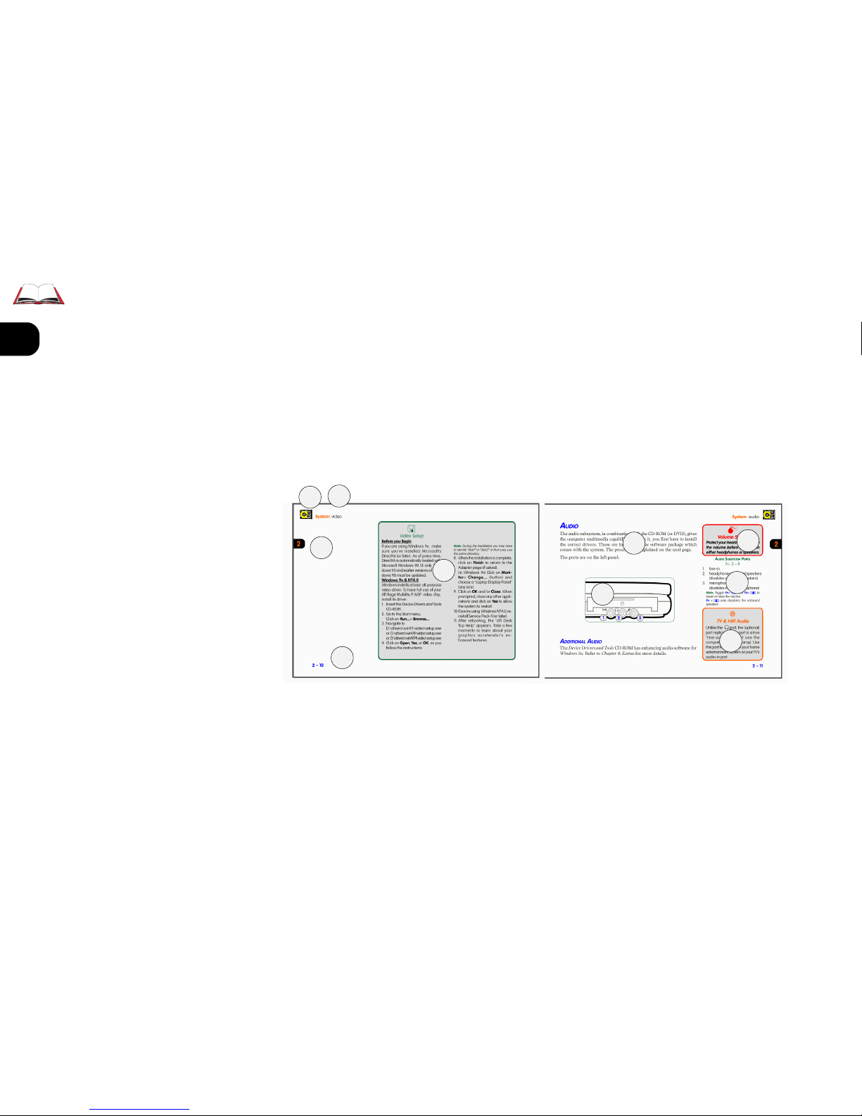
MANUAL LAYOUT KEY
FIG. 1– 1
1. chapter icon
2. chapter topic & quick key
3. chapter tab
4. setup text
5. page #
6. general/beginner text
7. graphic
8. warning text
9. graphic key
10. advanced user text
PACKING
Keep the packing materials in a safe place in case you need them for
shipping or long-term storage.
Introduction: manual contents
1
2
3
4
5
6
7
8
9
10
Page 23

1
2
3
4
5
6
7
8
1 – 3
QUICK STA RT GUIDE
This quick start guide assumes
that you’re already familiar with
notebook computers and can tell
at a glance what and where all the
key components are.
If you’re not that comfortable with
this sort of device, take a look at
the following pages for an overview of the system.
You should review these steps, be-
fore you take any action. If you
aren’t sure about one of the procedures, check the relevant chapter before continuing.
1. Follow the safety instructions on
page iv, especially the instructions
on placement.
2. Remove all packing materials, CDROM disks, floppy disks and any
PC Cards.
3. Secure the main battery pack in its
compartment. (Ch. 5)
4. Plug in/connect the modules.
(Ch.3)
5. Securely attach any peripherals
you want to use with the notebook
(i.e. mouse or keyboard) to their
ports. (Ch. 1)
6. Attach the AC adapter to the port
on the computer’s rear. (Ch. 5)
7. Plug the AC power cord into an
outlet.
8. Connect the AC power cord to the
AC adapter.
9. Raise the lid/LCD to a comfortable
viewing angle. (Preface)
10.Push the button (On/Off button)
to turn “on”.
Battery Charging
When you get your system, the
battery(ies) may not be fully
charged. Follow the procedure in
Chapter 5: Power, First-Time Use
and Storage
(page 5-4), to charge
the battery.
Save to Disk
Considerations
If you’re setting up your system
and plan to use the
Save to Disk
partition option in the future,
make sure your hard disk has
enough
unpartitioned
and
unformatted
space left to accommodate the size of the file or partition you expect to have. Refer to
Chapter 5: Power
for details.
Introduction: manual contents
Page 24

1
2
3
4
5
6
7
8
1 – 4
SYSTEM MAPS
The notebook has a lot of built-in features. The operating system automatically enables most of them. Further explanations (if necessary) of
the various subsystems are covered in the chapters or pages indicated.
Graphics Note: The illustrations in this manual are generalized representations. Your notebook’s
features may be shaped differently, but the functions we’ve described are identical.
FRONT VIEW
Latch To open the notebook cover, slide this latch to the right.
LCD Refer to Chapter 2: System for a description of the video
system.
LEDs Page 1–6 has a quick guide of their definitions.
Keyboard Page 1–7 has a quick guide to the “hot keys”.
Chapter 2: System has more on how to use the keyboard.
TouchPad Chapter 2: System covers basic functions.
Introduction: front view
Page 25
1
2
3
4
5
6
7
8
1 – 5
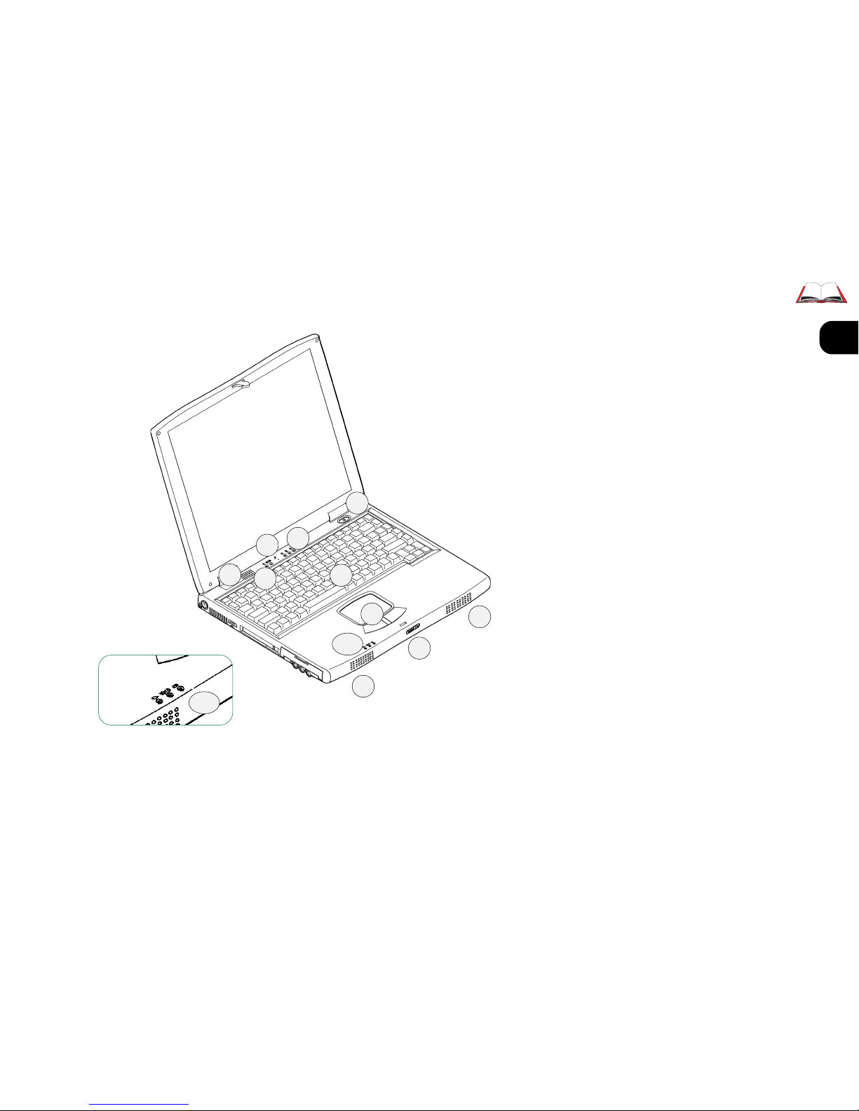
FRONT VIEW
FIG. 1– 2
1. vent
2. drive status LEDs
3. microphone (2– 11)
4. keyboard Function LEDs
5. ON/OFF & Suspend/Resume
button
6. Keyboard (2– 2)
7. AC-in LED
8. power status:
Power ON/Suspend
9. power status: Battery
10. TouchPad & buttons (2– 4)
11. speakers (2– 11)
12. latch release
Note: Detailed battery status is reported
by the Operating System’s power management utility.
Introduction: front view
1
2
3
4
5
6
7~9
10
11
12
11
7~9
Page 26
1
2
3
4
5
6
7
8
1 – 6
ICON
V
ARIABLE
M
EANING
N
OTES
ON/O
FF
S
USPEND/RESUME
TO T
URN
ON: H
OLD FOR ABOUT 1 SECOND
TO T
URN
OFF (
FORCED
-
N
OT RECOMMENDED
)
: HOLD FOR 2 SECONDS
(APM)
HOLD FOR 4 SECONDS
(ACPI)
- USE START MENU SHUT-DOWN PROCEDURES INSTEAD
S
USPEND/RESUME*: HOLD FOR ABOUT 1 SECOND
(APM & ACPI)
- SUSPEND METHOD DEPENDS ON SYSTEM SETTING
*
FLASHING
S
USPEND MODE
SOLID
P
OWER-ON MODE
SOLID
AC
ADAPTER IN USE
I
F RUNNING ON BATTERY POWER: BATTERY CHARGE IS IN "NORMAL" RANGE
I
F RUNNING ON ADAPTER POWER : BATTERY IS NOT CHARGING
OR
B
ATTERY IS NOT PRESENT
(
NO LIGHT
)
N
OT CHARGING
G
REEN
B
ATTERY FULL
U
NLESS THE ADAPTER STAYS PLUGGED IN, THIS DOESN’T LAST LONG
.
O
RANGE
B
ATTERY CHARGIN
G
B
ATTERY IS CHARGING
.
RED
FLASHING
(
WITH WA RNING "BEEPS
")
L
OW POWER
A
UTO
-S
USPEND
IMMINENT
:
C
ONNECT THE AC POWER SUPP LY IMME DIATEL Y OR SHUT DOWN
.
SYSTEM WILL INITIATE "
CRITICAL" OR "LOW POWER"
V
ERY SOON
.
-
POWER MANAGEMENT METHOD DEPENDS ON SYSTEM SETTING
*
CD/DVD-R OM
OR
FDD/LS-12
IN USE
* ACPI - T
HE SYSTEM SETTING IS CONTROLLED FROM WITHIN THE OS
(C
ONTROL PANEL > POWER MANAGEMENT).
SUSPEND/RESUME DEFAULT = SHUTDOWN
C
RITICAL POWER DEFAULT = STANDBY
APM - T
HE SYSTEM SETTING CAN BE CONTROLLED FROM THE SETUP UTILITY
.
SUSPEND/RESUME = SUSPEND
L
OW POWER = SAVE TO DISK (IF AREA IS PREPARED
)
SUSPEND (WITHOUT SAVE TO DISK AREA
)
S
ETTINGS CAN INCLUDE
SAVE TO DISK
(HIBERNATE), WHICH TURNS THE SYSTEM
OFF
AFTER IT HAS RECORDED THE SYSTEM STATE
.
F
OR MORE ON POWER MANAGEMENT, REFER TO
C
HAPTER 5: POWER
.
HDD
IN USE
NUML
OCK ACTIVATED
C
APSLOCK ACTIVATED
S
CROLLLOCK ACTIVATED
B
ATTERY CHARGE STATUS IS MORE COMPLETELY REPORTED BY
AN
APM
OR
ACPI
COMPLIANT OPERATING SYSTEM
(OS).
(E.G. WINDOWS
98).
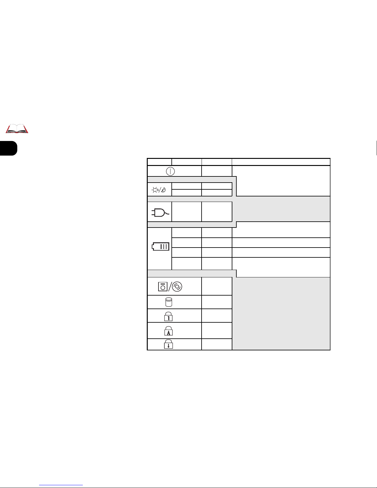
TABLE 1– 1
LED INDICATORS
LEDS
The system uses 8 LEDs to tell you about itself:
Introduction: LED definitions
Page 27
1
2
3
4
5
6
7
8
1 – 7
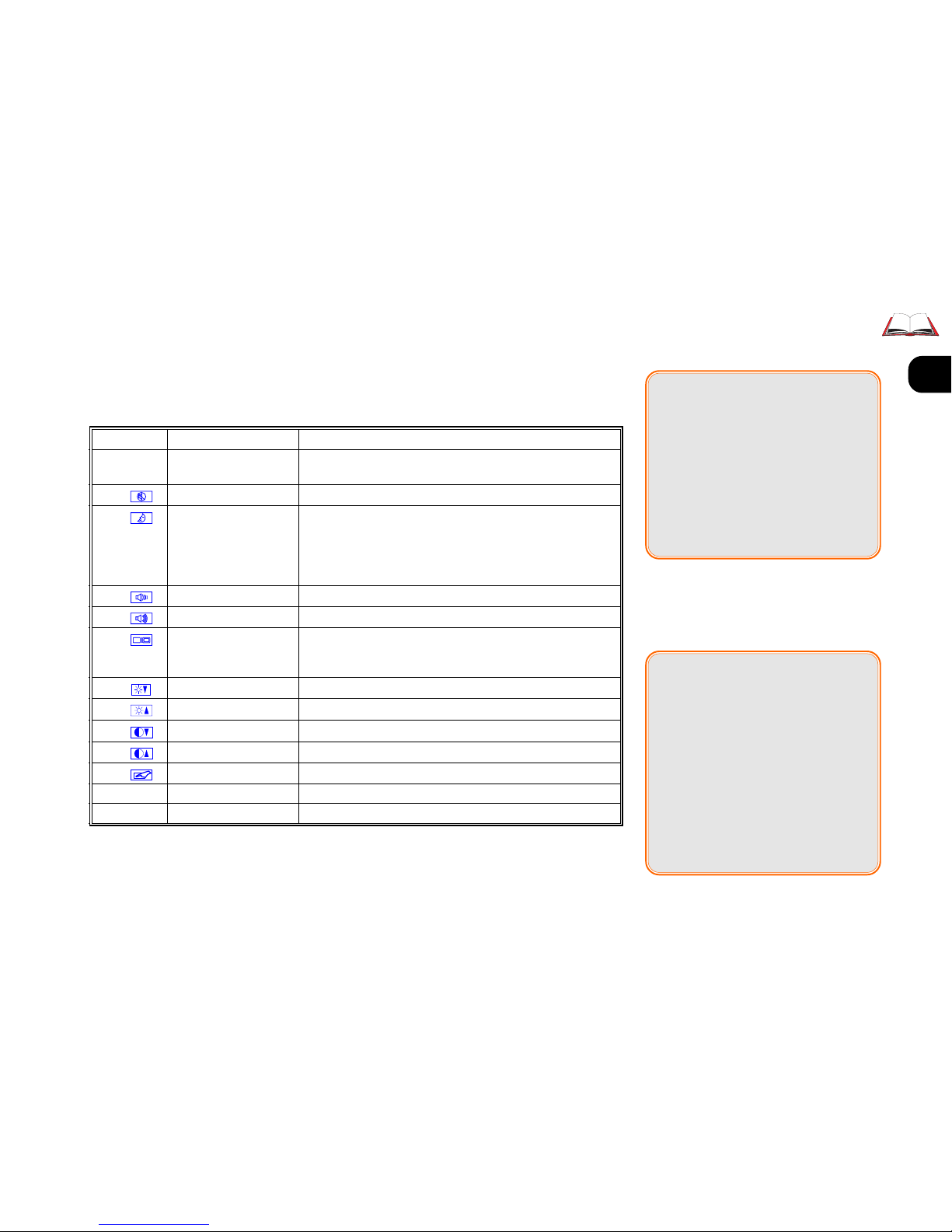
HOT KEY CONTROLS
Some of the system’s features are managed by Fn + Key combinations:
TABLE 1– 2
HOT KEY CONTROLS
Keys Control Comment
F2 enter
Setup
If pressed immediately after boot-up,
this starts the Setup utility
Fn + Speaker Mute turns off speakers & phones
Fn + freeze activates “Save to Disk” if the Save to Disk partition/file is
available and selected in the CMOS Setup, otherwise
activates “Suspend” (to RAM). Press this key again or the
Power button to “unfreeze” from the “Suspend” (to RAM)
state.
Fn + volume down reduces audio volume, releases “mute” function.
Fn + volume up increases audio volume, releases “mute” function.
Fn + Both/LCD/monitor/TV toggles between display devices: LCD + monitor, LCD
only, monitor only, and TV-out (refer to video setup information)
Fn + brightness down reduces LCD brightness
Fn + brightness up increases LCD brightness
Fn + contrast down reduces LCD contrast (DSTN screens only)
Fn + contrast up increases LCD contrast (DSTN screens only)
Fn + TouchPad Toggles the Touchpad on or off
Fn+ ScrLk Scroll Lock Toggles this function on or off
NumLock Number Lock Toggles the embedded numeric keypad on or off
Contrast Controls
Your computer’s keyboard may
include contrast controls. However, if your computer has a TFT
(Active matrix) screen, they are
disabled.
TFT screens have excellent contrast ratios, so contrast controls
are not needed.
;;
;;
;
Key Combinations
Whenever you use a key combination, start pressing them in the
order they are listed. Don’t release
any of the keys in a sequence until
you’ve pressed the last one.
Introduction: hot key controls
Page 28

1
2
3
4
5
6
7
8
1 – 8
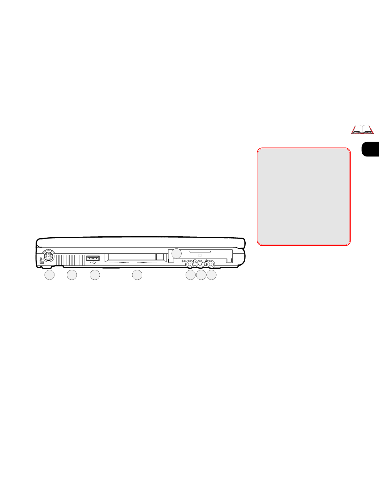
LEFT VIEW
[PS/2] Use this with any
standard PS/2 external keyboard or mouse. For details,
refer to Chapter 2: System,
“TouchPad”.
[Fan]
[USB] Windows 98 auto-
matically enables this port.
Windows 95 users should
refer to Chapter 2: System for
setup instructions. Windows
NT4 doesn’t support this
port.
Introduction: left view
00
00
0
Fan Warning
Do not block the fan. Overheating may cause the system to become unstable.
;;
;;
;
Parallel to USB Adapters
If you plan to use one of these
adapters, make sure a USB driver
is available for your device.
Consult the device’s manufacturer
for the latest driver options. – You
can usually do this on the Internet.
[PC Card] Your computer
uses newer technologies
than the drivers included in
Windows 95. Refer to the
setup procedure detailed in
Chapter 2: System (p. 2-15).
[HDD Module] Refer to
Chapter 5: Power and Chap-
ter 5: Extras for more on
how to setup or replace an
HDD.
[Audio] Setup for this subsystem is covered in Chap-
ter 2: System (p. 2-12).
Page 29
1
2
3
4
5
6
7
8
1 – 9
00
00
0
Drive Warning
Don’t try to remove the hard disk
(HDD) while the system is on. This
could result in data loss or damage.
Note: Unauthorized removal or
tampering with the HDD may
violate your warranty. If you are
in doubt, consult your dealer or
service representative
Introduction: left view
LEFT VIEW
FIG. 1– 3
1. PS/2 port (2-3)
2. Fan
3. USB ports (2-18)
4. PC Card slot (2-13)
5. HDD module (6-3)
6. audio line-in (2-11)
7. phones (2-11)
using this port disables the
speakers.
8. mic (2-11)
1 2 3 4
5
6 7 8
Page 30
1
2
3
4
5
6
7
8
1 – 10
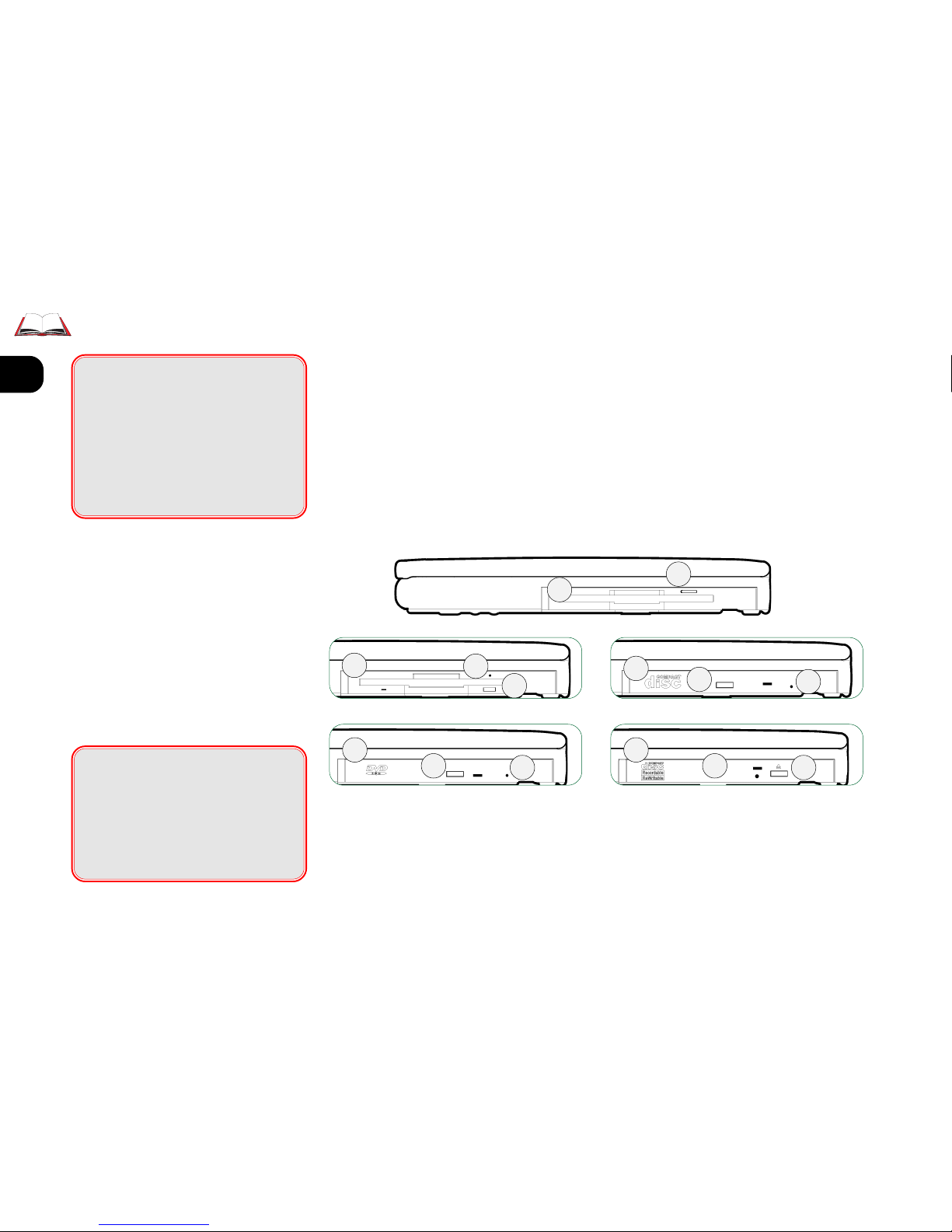
RIGHT VIEW
[FDD/LS-120] If your configuration comes with an LS120 Super Drive, refer to
Chapter 3: Device Bayfor
more on how to set it up
Introduction: right view
RIGHT VIEW
FIG. 1– 4
1. FDD
2. LS-120 Super Drive
3. CD-ROM
4. DVD-ROM
5. CD-RW
6. eject button
7. emergency eject button- uses a
probe (e.g. a straightened
paperclip).
[CD-ROM/DVD] Refer to
Chapter 3: Device Bay for
more on how to setup these
drives.
Note: Some operating systems (e.g.
Windows NT4) do not support DVD
functions. Ask your authorized service provider about driver support.
00
00
0
Swap Warning
Do not swap drive modules while
the system is ON (or in Suspend/
Save To Disk mode). This may
cause data-loss or make the system hang.
00
00
0
OS Warning
Some operating systems do not
support LS-120 drives and/or
DVD-ROM functions.
1
2
3
4
6
6
6
6
7
7
7
5
6
7
Page 31

1
2
3
4
5
6
7
8
1 – 11
MEDIA CARE & HANDLING
CD/DVD DISKS
Gently insert the disk (with its label side up) into the drive until the
disk “clicks” into place.
Press the button on the right of
the slot to eject the disk.
FDD & LS-120 CARE
Following are a few tips on the
proper handling of floppy and LS120 disks:
• Store disks away from magnetic fields and extreme temperatures. These conditions
can damage your data. It’s
also a good idea to make
backup copies of software
and data.
00
00
0
Media Warning
Don’t try to remove a floppy disk
or LS-120 while the system is accessing it. This may cause the
system to “crash”.
Introduction: right view
• If a disk label is already on
the disk, use a soft-tipped pen
to write on the label. This
prevents damage to the disk.
Don’t use a pencil - its carbon particles can rub off inside the drive.
• Do not remove any disk
from the drive when the
LED is flashing (in-use).
• Do not try to clean, bend, or
throw disks.
• Do not touch or scratch any
exposed portion of the disk
medium. Don’t pull open the
protective door either - this
lets dust get inside.
Page 32

1
2
3
4
5
6
7
8
1 – 12
REAR VIEW
The principal peripherals plug in on this panel. To be safe, turn off
both the system and peripherals before connecting them. Turn the pe-
ripherals on first, before you turn on the system.
Introduction: rear view
[Kensington Lock] This is a
standard security port.
IrDABy default, this port
uses (serial) COM2 resources. The infrared connection supports the SIR,
FIR and ASK standards. Its
most common use is for a
printer, modem or LAN.
;;
;;
;
IrDA Setup
Newer versions of
Windows 9x
have an IrDA driver built-in. For
older versions, support is available from Microsoft Corp. For other
operating systems and IrDA standards, consult your system vendor. Also consult the user’s guides
for the device this port is going to
work with.
Printer types
Your operating system may include drivers for many printer
models. Consult your printer
dealer for the most recent driver
for your model, as this can greatly
affect the performance of the
printer.
(Fax/Modem) RJ-11 modem/phone line (Chapter 2:
System).
TV-out (S-Video)
[Parallel/Printer] This
port supports several standards:
Output only
Bidirectional
ECP (Extended Capabilities)
EPP
Most printers use the Bidirectional mode. The Setup’s
“Help” column (refer to
Chapter 4: Firmware) explains how to adjust this setting. Your peripheral’s
manual explains how to configure the device.
Page 33

1
2
3
4
5
6
7
8
1 – 13
[COM1 (serial)]This port
works with any 9-pin serial
device (e.g. a mouse, serial
printer or modem).
For pointing devices, refer
to Chapter 2: System. For
other connections, consult
the device’s user’s guide(s).
[External Monitor] Use
Introduction: rear view
REAR VIEW
FIG. 1– 5
1. Kensington lock port
2. IrDA port (1-12)
3. Fax/Modem (2-17)
4. TV-out port
5. parallel/printer port (1-12)
6. COM port (1-12)
7. external monitor port (2-8)
8. adapter port (5-3)
this port with any standard
color VGA monitor. For details, refer to Chapter 2: Sys-
tem.
[adapter] Refer to
Chapter 5: Power and Appendix A: Specifications for de-
tails about the power system.
1
2
3
4
5
6
7
8
Page 34

1
2
3
4
5
6
7
8
1 – 14
BOTTOM VIEW
There are three compartments on the notebook’s bottom none of which
you should have to use frequently:
00
00
0
Upgrade Warning
Carefully review all the instructions about upgrading the system
memory. Also check with your
dealer to be sure that opening a
compartment does not violate
your warranty.
[Battery] This is part of the
power system, covered in
Chapter 5: Power.
[RAM] This contains the
system memory, covered in
Chapter 6: Extras.
[Device bay] This contains
one of five modules: FDD,
LS-120, CD-ROM, CD-RW
or DVD-ROM.
Note: Some operating systems do not
support all devices. Ask your authorized service provider about driver support.
Introduction: bottom view
BOTTOM VIEW
FIG. 1– 6
1. Device bay
2. Battery bay
3. RAM bay
1
2
3
Page 35

1
2
3
4
5
6
7
8
2 – 1
SOFTWARE NOTES
This chapter only covers essential
setup instructions in the Windows
9x, and NT operating systems.
Supplemental software is covered
in Chapter 6: Extras. For other operating systems (e.g. Windows 95,
Linux), check the “readme.txt” file
on the “root level” of the Device
Drivers & Tools CD-ROM, or consult your dealer.
Service Packs,
Versions & Updates
Our descriptions are based on:
Windows 98
(ver. 4.10.1998*)
Windows 98 Second Edition
(ver.4.10.2222A*)
Windows NT4
(Service Pack 4)
†
Windows 2000 Professional Ed.
(Build 2195).
*To check your version number, click on
Control Panel>System (General tab) .
†
Appears in the startup screen.
2 System
This chapter is about computer’s main built-in subsystems
Onboard Systems: Keyboard, TouchPad, Video and Audio
Communications: PC Card, Fax/Modem and USB
Setup Note: If you’re setting up your system for the first time, install these critical drivers in the
following order: USB and Intel 82371 (page 2-18); Direct X7 .0 or later (page 2-10) ; Video (page
2-10), and Audio (page 2-12).
ASSUMPTIONS
In our explanations, we assume
your system is configured so the
CD device is “drive D:”. If the driver
is located somewhere else, just substitute that source in the configuration.
For driver installations, we also
assume your system is setup to view
all files and file extensions.
Networking Note
Make sure you’ve downloaded
the driver from the network
source to your hard drive before
you begin any installation. In
some cases, the operating system must reboot as part of the
installation process and reconnecting to the network may not be
practical.
Page 36

1
2
3
4
5
6
7
8
2 – 2
ØØ
ØØ
Ø
KEYBOARDS
Your computer’s Keyboard has all the functions of a full-sized AT-compatible Keyboard plus a few extras:
Type These keys are like those on a typewriter.
Function Many operating systems (and applications) use these keys to
access special features, so you should consult those manuals.
Hot Keys These keys (and combinations) control some of the hard-
ware. Refer to page 1-7.
Special Characters
Some software applications allow
the number-keys to be used with
Alt to produce special characters.
These special characters can only
be produced by using number
keys on the embedded numeric
keypad. Regular number keys
won’t work.
System: keyboard
TYPE KEYS
FIG. 2 – 1
Press NumLock to turn on the
embedded numeric keypad
(outlined) – the LED will light.
FUNCTION KEYS
FIG. 2 – 2
Page 37

1
2
3
4
5
6
7
8
2 – 3
ÛÛ
ÛÛ
Û
EXTERNAL KEYBOARDS
You can attach an external Keyboard to the
(PS/2) port. If you
don’t have a 6-pin Keyboard connector, use a 5-to-6 pin adapter
cable. The system automatically
detects and enables the external
Keyboard as well as the notebook’s.
However, for those functions requiring the Fn key, you will still
need to use the notebook’s Keyboard.
This port can only accept one type
of device configuration per system
session. For example, if you connect
a PS/2 mouse to this port, you cannot connect a Keyboard to the port
during the same system session.
Doing so will cause a system conflict. If you already have a mouse
attached, and want to use a Keyboard instead, you must shut down
and restart the system. However,
you can detach and reconnect the
same device during a system session.
PS/2 PORT
FIG. 2 – 3
System: keyboard
Page 38

1
2
3
4
5
6
7
8
2 – 4
1
2
3
TOUCHPAD
The system automatically enables the built-in TouchPad. So, if you’re
using any version of Windows, you don’t have to install any other drivers
for it.
System: TouchPad
Configuring the
TouchPad
The TouchPad is a factory enabled
PS/2 device. It can use the “Microsoft, or IBM PS/2” mouse driver
available with most operating
systems.
THE TOUCHPAD
FIG. 2 – 4
1. sensor pad
2. left “mouse” button
3. right “mouse” button
Note for left-handers: Most operating
systems allow you to reverse the mousebutton settings.
Page 39

1
2
3
4
5
6
7
8
2 – 5
TouchPad
& Serial Device
Windows
1. Attach the serial device when
the system is off.
2. Turn on the system and allow
the operating system to detect
and configure the device on
the serial port (COM1), or run
the
Add/Remove Hardware
Wizard
(in the Control Panel) Insert the manufacturer’s driver
disk(s) if required.
3. Both devices are enabled.
Return to TouchPad (exclusively):
1. Exit the operating system (i.e.
Windows 9x
family or
Win-
dows NT 4.0
).
2. Detach the serial device.
3. Start the operating system. It
will automatically enable the
available pointing device, in
this case the TouchPad.
To find out how to change mouse settings
for other operating systems, consult the
manuals for those operating systems.
System: TouchPad
TOUCHPAD
& SERIAL DEVICE
If you want to use a serial device
as well as the TouchPad, you must
make sure the device’s driver can
“see” it on COM1 (the port). In
some operating systems, you can
only use one pointing device driver
at a time, either serial or PS/2. To
use a serial device, first enable it
by attaching it to the port (while
the system is OFF) and then start
up and configure it with a suitable
driver.
TOUCHPAD
& PS/2 DEVICE
You can also use a mouse connected
to the
(PS/2) port. Just make the
connection, and the system automatically detects the mouse when
it starts up, using the same driver
for both devices.
Note: The PS/2 port only accepts one type
of device per system session. If you want to
switch to an external Keyboard on this port,
you must shut down and restart the system.
However, you can detach and reconnect the
same
device during a system session.
DISABLING THE TOUCHPAD
If you want to disable the TouchPad so that it isn’t activated by mistake,
use the Fn +
key combination to toggle the TouchPad ON or OFF.
You can also enable or Disable in Setup. However, if the pointing device
is disabled or on a disabled port when the computer starts up, the operating system won’t load the driver and even this toggle won’t make it work.
Refer to Chapter 4: Firmware for more on the Setup utility.
Page 40

1
2
3
4
5
6
7
8
2 – 6
1 2 3
0
Protect the LCD
Do not allow any foreign objects
(i.e. paper or plastic) to get between the lid/LCD and the work
panel. They could damage or
scratch the LCD and/or accidentally activate the close-cover
switch.
VIDEO
There are three display options:
• the notebook’s LCD
• an external monitor (VGA)
• a TV (through the optional port replicator)
Select between the LCD and VGA or both with the Fn +
toggle or the
controls embedded in the video driver interface. The interface also lets
you select a TV output, or change the screen resolution and color output
to whatever is most comfortable/efficient for you.
As you examine the video driver (see below for setup information), you’ll
notice that some displays have more flexibility than others. This is a
matter of hardware, video memory and the driver for your operating system. The driver interface shows the available options.
System: video
LCD
AS you open the lid, adjust it so you can look at the screen straight-on,
without any glare. If necessary, adjust the brightness controls.
THE LCD CONTROLS
FIG. 2 – 5
1. Display toggle (LCD/CRT)
2. Brightness controls
3. Contrast controls
(for DSTN screens)
Screen Controls
Your computer’s keyboard may
include contrast controls. However, if your computer has a TFT
screen, they are disabled.
TFT (active matrix) screens have
excellent contrast ratios, so contrast controls aren’t needed.
Page 41

1
2
3
4
5
6
7
8
2 – 7
1
2
3
ÛÛ
ÛÛ
Û
VIDEO DRIVER CONTROLS
The video driver adds three additional pages to the “Advanced” button
of the “Setting” tab of Display Properties to support the new enhanced
display features. The added pages allow you to select output devices
(Display page), to adjust the position and size of your screen (Adjust-
ment page), as well as to correct color tone differences between real
color values and the way your monitor or flat panel displays them (Color
page).
WINDOWS 98
DISPLAY PROPERTIES CONTROL
FIG. 2 – 6
Click on the ATI icon (1) in the tray
and navigate to “Display Settings”(3). Click again to launch the
Display Properties control utility.
System: video
Page 42

1
2
3
4
5
6
7
8
2 – 8
ATTACHING A MONITOR
If you prefer to use an external monitor, connect it to the VGA port on
the rear panel.
Note: The vertical refresh rate of your monitor is very important. If it’s too low and/or you’re using
fluorescent lighting, the screen will appear to flicker. To reduce flickering on an external monitor, use
faster refresh rates (we recommend a refresh rate of 72Hz or more). But first check your monitor’s
documentation to make sure it can support the rates listed by the video driver. The default refresh
rate for VGA monitors (without drivers) is 60Hz.
System: video
00
00
0
Power Warning
Both the computer and any other
display should be OFF before you
connect them.
00
00
0
TV Type
Be sure the NTSC/PAL setting in
the display control panel is correct
(click on the “TV” tab). The wrong
setting could damage your TV.
TV
While the system is OFF, connect
the TV to the TV-out port. Then
restart your system.
Note: The default refresh rate for NTSC and
PAL TVs is fixed at 60Hz and 50Hz, respectively.
Display Note: When turned on at the same
time, either the TV or panel will automatically switch to “Secondary” .
SWITCHING
You can switch to the VGA display
using the video driver control panel
or by toggling Fn + . The toggle
sequence is shown in Table 2-1.
Page 43

1
2
3
4
5
6
7
8
2 – 9
TV
Standard
Monitor
Resolution
Toggle Sequence Comment
NTSC
+
PAL
VGA (640 x 480)
Both (LCD + Monitor) >
LCD >
Monitor >
TV
†
The toggle sequence cycles through the 4 device settings.
However, if the video driver does not support a particular resolution for
the selected device, the output may be blank or garbled.
The video driver interface overrides the toggle control.
SVGA (800 x 600)
XGA (1024x768)
sm a ller LC D s use panning feature.
SXGA (1280x1024) LCDs & TV output use panning feature.
* TV output is only availab le through the (optional) port replicator. M ake su re all co nnections are made, and the TV is ON before turning on the computer.
†
"Dual View with Different Disp lay" features are not available in Window s 95 or NT4.
WINDOWS 98
DISPLAY PANEL SETTINGS
FIG. 2 – 7
System: video
TABLE 2 – 1
VIDEO OUTPUT K EY COMBINATION
SEQUENCE
Dual View
& Different Display
To get this effect, you must select
the “ Secondary” display and
check the “Extend my Windows
desktop into this monitor” switch.
Page 44

1
2
3
4
5
6
7
8
2 – 10
System: video
5. When the installation is complete,
click on Finish to return to the
Adapter page (if asked).
(in
Windows 9x
) Click on Moni-
tor> Change... (button) and
choose a “Laptop Display Panel”
(any size).
6. Click on OK and/or Close. When
prompted, close any other applications and click on Yes to allow
the system to restart.
7. If you’re using
Windows NT4.0
, re-
install Service Pack 4 (or later).
8. After rebooting, the “ATI Desk
Top Help” appears. Take a few
moments to learn about your
graphics accelerator’s enhanced features.
Video Setup
Before you Begin
If you are using Windows 9x,
make sure you’ve installed
Microsoft’s DirectX7 (or later).
1. Insert the
Device Drivers and
Tools
CD-ROM.
2. Go to the Start menu,
Click on Run...> Browse...
3. Navigate to
D:\drivers\win98\DirectX\
(your language)\
DX70eng.exe*
or D:\drivers\win95\DirectX...
* The “DX70xxx.exe” file name reflects the
language (e.g. English = DX70eng.exe,
but Italian = DX70itn.exe).
4. Click on Open, Ye s, or OK as
you follow the instructions.
You’ll also have to restart during the process.
Windows
Windows installs a basic all-purpose
video driver. To have full use of your
ATI Rage LT Pro AGP video chip, install its driver:
1. Insert the
Device Drivers & Tools
CD-ROM.
2. Go to the Start menu,
Click on Run...> Browse...
3. Navigate to
D:\drivers\win95\video\setup.exe
or D:\drivers\win98\video\setup.exe
or D:\drivers\winNT4\video\setup.exe
or
D:\drivers\win2000\video\setup.exe
4. Click on Open, Ye s, or OK as you
follow the instructions.
Note: During the installation you may have
to identify “disk1” or “disk2”. In that case, use
the same directory.
Page 45

1
2
3
4
5
6
7
8
2 – 11
1
2 3
AUDIO
The audio subsystem, in combination with the CD device, gives the
computer multimedia capabilities. To use it, you first have to install the
correct drivers. These are included in the software package which comes
with the system. The procedure is explained on the next page.
The ports are on the left panel:
AUDIO SUBSYSTEM PORTS
FIG. 2 – 8
1. line-in
2. headphones/external speakers
(disables on-board speakers)
3. microphone
(disables internal microphone)
Note: Toggle Fn+ and Fn+ to
lower or raise the volume.
Fn + only disables the onboard
speakers
System: audio
00
00
0
Volume Safety
Protect your hearing! Turn down
the volume before you plug-in
either headphones or speakers.
Page 46

1
2
3
4
5
6
7
8
2 – 12
Audio Setup
Note for Windows 95: Y
ou should install the USB & related Chipset drivers
(refer to page 2-18 of this chapter) before proceeding.
This procedure “updates” the default driver
Boot-up the system and Insert the
Device Drivers & Tools
CD-ROM.
Windows 9x
1. Press
áá
áá
á+Break*> Device
Manager (tab) .
2. Highlight !PCI Multimedia De-
vice then click on the Remove
button to delete it.
3. Repeat this for !PCI Input Con-
troller (if it appears).
4. Click on the Refresh button.
5. If you’re installing the audio
driver for the first time (instead
of upgrading), the
Add New
Hardware Wizard
will appear.
Choose the “Search for best
driver” option > Next>
†
Note: For “specify location”, Browse...
to the “audioMDC” or “ audio” direc-
6. Check the “Optional Search Location” box, then choose “specify a
location”.
†
7. Click on Next or Finish as they ap-
pear and let the system load its
various drivers.
8. Repeat as necessary for associated “hardware”.
9. Close Device Manager (use the
“x” in the upper right corner).
10.Shutdown
Windows
and restart
the system.
Windows NT4.0
1. Open Control Panel> Multimedia
> Devices (tab) and click on the
Add... button.
2. Highlight “Unlisted or Updated
Driver” and click on OK.
3. Click on Browse... and navigate
to the NT4 “audioMDC” or “audio”
directory.
†
4. Click on OK > OK.
5. Highlight the driver then click on OK.
6. Confirm the settings.
7. Close the Device Manager and
restart the system.
*
áá
áá
á+Break =
Start > Control Panel > System
tory for your operating system on the
Device Drivers & Tools CD-ROM. Use
“audioMDC” if your system includes an
on-board modem. Use “audio” if it doesn’t.
6. Click on Next or Finish as they ap-
pear and let the system load its
various drivers.
7. Click on OK to confirm the settings
and close
System Properties
.
8. Shutdown
Windows
and restart the
system.
Windows 2000
1. Press
áá
áá
á+Break*> Hardware (tab)
> Device Manager (button) .
2. Highlight !PCI Multimedia Device
then choose “Uninstall” from the
“Action” menu to delete it.
3. Repeat this for !PCI Input Control-
ler (if it appears).
4. Click on Scan for Hardware
Changes in the “Action” menu.
5. If you’re installing the audio driver
for the first time (instead of upgrading), the
Found New Hardware
Wizard
will appear.
Choose the “Search for suitable
driver” option > Next>
System: audio
Page 47

1
2
3
4
5
6
7
8
2 – 13
2
1
COMMUNICATIONS
PC CARDS
The notebook has one Type II PC Card expansion socket. It can also
handle a Type I card. The socket supports several standards:
• PCMCIA (rev. 2) Both Type I and Type II.
• CardBus PCI bus to PCMCIA socket.
PC CARD SOCKET
FIG. 2 – 9
1. socket door
2. eject button
INSERTING A PC CARD
This part of the system needs two drivers:
1. a socket driver which is part of the operating system
2. a device driver which comes with the PC Card itself.
System: PC Card
Page 48

1
2
3
4
5
6
7
8
2 – 14
ÜÜ
ÜÜ
Ü
System: pc cards
Plug ‘n play operating systems
(e.g. Windows 9x) can recognize
most PC Cards and automatically
install the right driver(s). If it
doesn’t have the driver, it will ask
you to supply one from a disk provided by the PC Card’s manufacturer. Non-plug ‘n play OSs won’t
prompt you for driver information,
but still need it - check your operating system and PC Card documentation.
Once the driver is installed, Win-
dows allows you to “hot” insert
and remove the PC Card - within
limits. Refer to your operating system manual for more on this.
When you insert a card correctly,
the system beeps once. If the PC
Card is not detected, check whether
the correct drivers are loaded.
REMOVING A PC CARD
In general, you should always
“mount” and “dismount” the PC
Card using the PC Card socket utility. (Click on the PC Card icon in
the Windows utility tray.)
When the utility tells you it’s safe,
push the eject button to remove
the card.
Note: If the button is flush with the side of
the computer and you want to make it
“pop” out, push it in slightly.
00
00
0
PC Card Changes
Do not add, remove or change
cards while the system is in Save
to Disk mode. This may cause a
conflict with the stored system
configuration information.
00
00
0
I/O PC Cards
Some operating systems like
Windows NT
, may not work properly if an I/O card (e.g. a LAN) is
present in the socket when you
restart the computer. Depending
on your operating system, the
COM ports (I/O) for PC Card devices are reassigned.
PC CARD - EJECTION
FIG. 2 – 10
Push the button in to eject the PC
Card.
Page 49

1
2
3
4
5
6
7
8
2 – 15
PC Card Setup
Windows 95
The PC Card socket uses technologies which are newer than
Windows
95
. Before installing these newer
drivers for
Windows 95
, you should
install the USB & related Chipset drivers (refer to page 2-18 later in this
chapter).
To upgrade the PC Card driver:
1. Insert the
Device Drivers & Tools
CD-ROM.
2. Go to the Start menu,
click on Run...>Browse...
3. Navigate to:
d:\drivers\win95\
pcmcia\setup.exe
4. Click on Open, Yes or OK as you
follow the instructions.
Note: During the installation, you may be
asked to instert the
Windows 95
disk.
5. When the installation finishes, al-
low the system to restart.
Windows NT 4.0
The operating system automatically
installs the PC Card socket drivers.
However, it is only PCMCIA (rev. 2)
compliant, so you can install or remove cards only when the system is
turned off. In particular, any I/O PC
Card (e.g. SCSI) must be present when
you boot-up the system. ZV support
is not available.
System: pc cards
Page 50

1
2
3
4
5
6
7
8
2 – 16
××
××
×
FAX/MODEM (OPTION)
If your system includes the fax/modem module, both Windows 9x, Windows 2000 and Windows NT 4.0 will detect it during setup. However,
our module takes advantage of newer technologies so you will have to
install our updated drivers to take advantage of its full speed.
FAX/MODEM PORT
FIG. 2 – 11
System: fax/modem
INTERNATIONAL CONSIDERATIONS
The Fax/Modem socket is designed for a standard RJ-11 telephone connection. Not all countries use this standard. So, before traveling to another country, check with your travel agent.
Page 51

1
2
3
4
5
6
7
8
2 – 17
Fax/Modem Setup
Windows Setup
The on-board fax/modem option is
integrated into the audio system.
If your system has this device, follow
the audio driver installation instructions on page 2-12, but be sure to
use the “audioMDC” drivers for your
operating system.
Once this driver is installed (and
you’ve restarted the system), the fax/
modem is ready to use.
Internet Access
To set up your system to work with a
Dial-up Internet Service Provider (ISP),
you must be sure to have all the
proper “protocols” installed (e.g. TCP/
IP). Refer to your operating system
manual for this and/or your ISP’s
documentation.
International Notice:
The default configuration is for the
United States. To use the modem
in another region/country,
1. Press
áá
áá
á+ Break* > Device Man-
ager. Highlight the modem and
click on the Properties button.
2. Choose your country on the Country Select tab.
*
áá
áá
á+Break =
Start > Control Panel > System
Security Notice
Be sure to check with your system
administrator to setup safeguards
appropriate for your environment.
Hint: If possible, do not allow sharing on the
TCP/IP protocol, and password protect
all
shared files.
System: fax/modem
Page 52

1
2
3
4
5
6
7
8
2 – 18
System: USB
USB & Related Chipset
Setup
The USB socket drivers were not
available with the initial release of
Windows 95
. This installation will correct that defect.
Enabling the USB features is a twostage process which must be followed in order:
Stage 1 USB setup:
Run the Usbsupp.exe utility from
Microsoft. This may be included on
the CD-ROM containing
Windows 95.
When the system restarts, continue
to Stage 2.
Stage 2 Chipset setup
Run
Setup.exe
of the Intel 82371xb INF
Update Installer ver. 3.0.
(drivers\win95\intel). When this is installed, the system will go through a
re-detection process, which may require several restarts of the system
(just follow the on-screen instructions).
Windows 98x
USB support is fully integrated.
Windows NT 4.0
USB support is not available.
Page 53

1
3
4
5
6
7
8
3 – 1
Networking Note
Make sure you’ve downloaded
the driver from the network
source to your hard drive before
you begin any installation. In
some cases, the operating system must reboot as part of the
installation process and reconnecting to the network may not be
practical.
3 Device Bay
This chapter is about setting up and using modules in the device bay:
CD-ROM DVD-ROM CD-RW
FDD LS-120
SOFTWARE NOTES
Like the last chapter, we only
cover essential setup instructions
in Windows 9x, 2000, and NT4
operating systems. For other operating systems, check the
“readme.txt” file on the “root
level” of the Device Drivers & Tools
CD-ROM, or consult your dealer.
ASSUMPTIONS
In our explanations, we assume
your system was installed with a
CD device in the device bay and is
“drive D:”. If the drivers are located
somewhere else, just substitute
that source in the configuration.
For driver installations, we also assume your system is setup to view
all files and file extensions.
Setup Note
If you’re setting up your system for
the first time, you should have already installed these critical drivers in the correct sequence –
USB and Intel 82371 (page 2-18)
Direct X7.0 or later (page 2-10)
Video (page 2-10)
Audio (page 2-12)
Page 54

1
2
3
4
5
6
7
8
3 – 2
Device Bay: connections
DEVICE BAY MODULES
There are five module options for the device bay, but the most practical configuration is to keep the CD device in the device bay. When
necessary, attach the FDD+adapter cable to the
port, or follow the
swapping instructions to install the LS-120 module.
Whenever any module is in use, the
LED flashes.
00
00
0
Bay Warning
Don’t leave the device bay empty.
Dust or other material could get
into the notebook and cause damage.
CONNECTION
Before swapping modules, follow the instructions on the next few pages
to prepare the system .
When you’re ready to install a module, just slide it into the bay until it
“clicks” into place.
To release a module, slide the locking latch on the bottom of the notebook to the unlock position and hold it. At the same time, grasp the edge
of the module and pull it out of the Device bay.
Page 55

1
3
4
5
6
7
8
3 – 3
Device Bay: switching
SWITCHING A MODULE
FIG. 3 – 1
1. To unlock, slide the locking
latch down.
2. Pull on the module’s grooved
edge to remove it.
3. Push in the module until it
“clicks” into place and its outer
edge is flush with the case.
1
2
3
ÝÝ
ÝÝ
Ý
ÛÛ
ÛÛ
Û
ÞÞ
ÞÞ
Þ
Page 56

1
2
3
4
5
6
7
8
3 – 4
Device Bay: swaping
SWAPPING
The safest way to swap modules is
to shut down the system first.
When you reboot, the plug n’ play
operating system automatically rescans the system and loads the appropriate resources.
In all cases, the operating system
asks for the appropriate drivers
when it detects a module for the
very first time.
WINDOWS 9X AND BAYSWAP
If you’re using Windows 9x, this
utility makes it possible to switch
modules without shutting down.
WINDOWS NT4.0
This operating system doesn’t
have a software solution. The system must be turned OFF first.
WINDOWS 2000
This operating system has its own
system for installing and
uninstalling “devices”.
Page 57

1
3
4
5
6
7
8
3 – 5
Device Bay: swaping
BaySwap Utility
Win 9x & BaySwap
Before you begin
If you are using
Windows 9x
, make
sure you’ve installed Microsoft
Internet Explorer 4 or 5. These utilities also install components needed
by BaySwap.
1. Insert the Device Drivers & Tools
CD-ROM.
2. Go to the Start menu,
Click on Run...> Browse...
3. Navigate to
D:\drivers\(YOUR OPERATING SYSTEM)
\bayswap\setup.exe
4. Click on Open > OK.
5. Select the appropriate language,
then click on OK, Next, Yes or Fin-
ish to allow the utility to set itself
up then restart the computer.
6. When the system resumes, the
Bayswap command will appear
in the tray on the lower right side
of the screen.
Windows 2000
This operating system has its own
“swapping system”:
1. Press
áá
áá
á+Break*> Hardware
(tab) > Device Manager (button).
2. Highlight the device you want
to remove. (either the “...CD/
DVD-ROM...” or “...LS-120...” or
“High-Capacity Floppy Disk
Drive”)
3. Click on the right mouse button, and choose “Disable”.
4. When the list stops refreshing
itself, remove the module and
swap in its replacement.
5. Click on the right mouse button again, and choose “Scan for
new hardware changes”.
6. After the menu refreshes itself,
should the new device appear
with an “x”, highlight it, click on
the right mouse button, and
choose “Enable”.
7. Close out Device Manager,
and use your new module.
Usage:
Right-(mouse) button click on the
icon for an options menu.
Left-(mouse) button click on the
icon for an activity menu.
Hot Method
1. Launch BaySwap from the tray on
the lower-right of the screen.
2. When the
BaySwap
dialog box appears, switch the modules. (Follow
the instructions on page 3-3.)
3. Click on OK to allow the system to
re-scan itself.
Warm Method
1. Put the system in suspend mode
(F n+ ).
2. Switch modules.
3. Resume full-power mode (press
Fn+ again).
4. Launch
BaySwap
from the tray on
the lower-right of the screen, and
allow the system to detect the
“new” hardware.
*
áá
áá
á+Break =
Start > Control Panel > System
ÛÛ
ÛÛ
Û
Page 58

1
2
3
4
5
6
7
8
3 – 6
CD DEVICES (CD-ROM, DVD-ROM & CD-RW)
MULTIMEDIA
If you’re using the CD-ROM (or
DVD/CD-RW) as a multimedia
playback device, you’ll need to use
various utilities. Windows 9x, NT
4.0 and 2000 automatically include
basic controls in their “Entertainment” packages (Start > Pro-
grams > Accessories > Multimedia or Entertainment).
;
DVD Limits
DVD functions are not available in
the
DOS, Windows 3.1x & Win-
dows NT 4
environments. They
can only “see” your built-in DVD
as an ordinary CD-ROM.
CD DEVICE DRIVES
FIG. 3 – 2
1. CD-ROM eject button
2. CD-ROM emergency eject
button. This requires a probe
(e.g. a straightened paper clip)
Device Bay: CD, DVD & CD-RW
DATA STORAGE
As a data storage device, the CDROM works like the other drives
in the My Computer window (or
File Manager in older versions of
Windows).
2
1
1
2
1
2
Page 59

1
3
4
5
6
7
8
3 – 7
To remove the disk, press the same button to release the tray. If the system
is OFF, you can open the tray by inserting a probe (e.g. a straightened paper clip) into the small hole next to
the eject button.
Audio CD
If you want to use the CD-ROM to
play an audio CD, make sure your
operating system has the necessary drivers installed.
Multimedia CD’s: MPEG
The ATI video driver automatically
supports MPEG decoding, so you
don’t have to install any special
hardware or software to play
Video CDs.
CD-R & CD-RW Care
If the surface of a “recordable” CD
is scratched, it will be “locked”.
Device Bay: CD, DVD & CD-RW
INSERTING & REMOVING
CD/DVD MEDIA
To insert a disk:
1. With the notebook turned
On, press the button on the
front of the module to release
the spring-loaded tray.
2. Gently pull the tray out to
its fullest extension.
3. Insert your disk shiny-side
down (like an audio CD).
4. Gently push the tray in until it clicks in place. The disk
is ready to play.
USING A CD-ROM
FIG. 3 – 3
1. Insert the disk face down.
2. Push the tray in until it
clicks in place.
ØØ
ØØ
Ø
1
2
ÛÛ
ÛÛ
Û
Page 60

1
2
3
4
5
6
7
8
3 – 8
Device Bay: CD setup
CD-ROM Drivers
DOS
These instructions assume you’ve
already installed some version of
DOS including the MSCDEX file.
1. If you do not have a floppy disk
with the CD-ROM driver on it,
your only other source is the
CD-ROM which accompanies
the system. Using a CD-ROM
drive on another computer,
navigate to the d:\drivers
\DOS\CD-ROM or d:\drivers
\DOS\DVD-ROM directory.
Copy the folder for your module onto a 1.44MB floppy.
2. Install the CD-ROM, DVD-ROM
or CD-RW module in the Device bay.
3. Connect the FDD adapter cable
to the FDD module.
4. Connect the FDD + Adapter
cable to the parallel port on the
rear panel.
5. Insert the floppy containing CDROM driver into the FDD.
Switch to drive A:\ and open its
driver directory, and type:
SETUP.EXE
6. As each page appears, press Y or
Enter to confirm the settings.
If you don’t want to install the driver
in the default directory (C:\ATADVD),
when the “Specify the directory...”
dialog box appears, use Back-
space to delete the current name,
then type in your preference. Remember to start the directory
name with C:\.
When you get to the “Specify the
parameter...” page, make sure the
( )/D [MSCD000] switch has an
asterisk (*). Then press Enter.
7. When the installation is complete,
remove the floppy disk and reboot
your computer.
Windows 9x
Windows NT4 & 2000
Follow steps 2 to 5 of the DOS installation. These operating systems automatically detect and configure the
CD-ROM drive. The start-up floppy
which comes with them should also
be able to configure the CD-ROM.
It they can’t, install a version of DOS
and the CD-ROM driver as described
above. Then follow the installation
utilities for the operating system you
plan to use. As the installation
progresses, the operating system
will replace, or modify our CD-ROM
driver.
Page 61

1
3
4
5
6
7
8
3 – 9
DVD Regional Coding
Region Where
1 USA, Canada & US Territories
2 Europe, Japan, South Africa, Middle East (including Egypt)
3 South East Asia, East Asia (but not China)
4
Australia, New Zealand, Mexico, Central & South America,
Caribbean and Pacific Islands
5
Former Soviet Union, Indian Subcontinent, Africa,
North Korea, and Mongolia
6 China (but not Hong Kong)
DVD-ROM & CD-RW Setup
(Windows 9x & 2000)
If you don’t install drivers and application software, the system “sees”
the DVD or CD-RW as an ordinary CDROM. To use all of the module’s functions,
1. Make sure the following
drivers are installed:
USB (page 2-18)
Video (page 2-10)
Audio (page 2-12)
2. Insert the CD-ROM with the DVD
or CD-RW utility software.
3. Go to the Start menu,
click on Run...>Browse...
4. Navigate to:
d:\setup.exe
5. Click on Open, Yes or OK as you
follow the instructions.
* DVD Note: Windows 98
allows lim-
ited region changes.
So, be careful
when choosing your region code. To
change your region, after you’ve
reached the limit, you must reinstall
Windows 98,
then redo the entire setup
again.
Note: This should be the last part of
the setup. Use the following sequence:
USB driver (
Win 95
)
Intel 82371 driver (
Win95
)
DirectX7.x (before Win98 SE)
video
audio
DVD utility
Device Bay: DVD & CD-RW setup
Page 62

1
2
3
4
5
6
7
8
3 – 10
Device Bay: FDD
FDD (FLOPPY) MODULE
The FDD can work equally well
in either the internal or external
position. It doesn’t need to be “set
up” attached or installed when you
boot-up. The system won’t “look”
for it until told to “look” at drive
A:.
00
00
0
FDD Removal Warning
Do not remove the FDD module
from the port or Device bay
while it is active. This could dam-
age the system, the FDD or result in data loss and/or corruption.
FDD STATUS INDICATOR
FIG. 3 - 4
The LED flashes whenever
the FDD is in use, either in the device bay or connected by the
adapter cable.
DEVICE BAY WITH FDD
FIG. 3 - 5
1. FDD
2. eject button
DEVICE BAY INSTALLATION
We recommend that you put the
system into Suspend mode, Save
to Disk, or better yet, turn it off
first. Then slide the FDD module
into the bay until it “clicks” into
place.
(Follow the instructions on page 3-3.)
DEVICE BAY REMOVAL
If you must remove the FDD module during a session, do it carefully
and either return the module to
the Device bay at a later time, or
turn the system OFF. Other drive
modules cannot replace the FDD
during the same session.
1
2
ÝÝ
ÝÝ
Ý
Page 63

1
3
4
5
6
7
8
3 – 11
Device Bay: FDD
EXTERNAL CONNECTION
If the Device bay is occupied (e.g. with a CD-ROM), you can connect
the FDD to the parallel port with its proprietary cable: Attach the
cable to the FDD module first, then attach the other end of the cable to
the port.
00
00
0
Cable Warning
The FDD+adapter combination
cable only works with the FDD
module.
If it’s connected to the port, the
cable must also be connected to
the FDD module or the system
may halt.
FDD PORT CONNECTION
FIG. 3 - 6
1. FDD module
2. FDD to adapter
3. (parallel) port
Disk Care
Refer to page 1-11 for more on how
to take care of your disks
2
3
1
Page 64

1
2
3
4
5
6
7
8
3 – 12
LS-120 MODULES
Unlike a standard FDD, the LS-120 only works in the Device bay.
In the My Computer window, the LS-120 drive appears as “Drive A:”
(even if you don’t have a FDD attached). Highlight it and click on the
right mouse button. As your cursor moves over its list of functions, a
brief explanation of each appears in the bottom of the window.
DEVICE BAY REMOVAL
If you must remove the LS-120
module during a session, do it carefully and either return the module to the Device bay at a later
time, or turn the system OFF.
Other drive modules cannot replace the LS-120 during the same
session, unless you use the
BaySwap utility (page 3-5).
DEVICE BAY INSTALLATION
Shut down the computer. Then
slide the FDD module into the bay
until it “clicks” into place.
(Follow the instructions on page 3-3.)
STARTUP CONSIDERATIONS
The LS-120 must be installed before you boot-up. If it isn’t in the Device bay when the system boots, the system won’t recognize it and
won’t allocate system resources.
When you turn on the computer, Press F2 to enter the Setup utility. In
the Main Menu, make sure the Secondary drive indicates “LS-120”.
00
00
0
Removal Warning
Do not remove the LS-120 module from the Device bay while it
is active. This could damage the
system, the LS-120 or result in
data loss and/or corruption.
Device Bay: LS-120
Page 65

1
3
4
5
6
7
8
3 – 13
USING AN LS-120
Insert an LS-120 disk just like a floppy disk. Press the button on the
right of the LS-120 drive to eject the disk (while the system is ON).
LS-120 & Windows
Windows 9x & 2000
If you remove the LS-120 module
without using the
BaySwap
utility,
the system will freeze and wait for
the drive to be reinstalled.
Windows NT 4.0
Shut down the system before
swapping the LS-120. If you removed the LS-120 module without shutting down, don’t try to access it. This will tell Windows NT
4.0 you’ve changed the system
profile and you won’t be able to
reinstall it without rebooting. As
long as Windows NT 4.0 doesn’t
look for the LS-120, it thinks it is
present.
DEVICE BAY WITH LS-120
FIG. 3 - 7
1. LS-120 Super Drive
2. eject button
3. emergency eject button- uses
a probe (e.g. a straightened
paperclip).
Device Bay: LS-120
1
2
3
Page 66

1
2
3
4
5
6
7
8
3 – 14
Device Bay: LS-120
NOTES:
Page 67

1
2
3
4
5
6
7
8
4 – 1
4 Firmware
This chapter is about the notebook’s built-in software:
Diagnostics: the POST (Power-On Self Test)
Configuration: the Setup utility
If your computer has never been set up, or you are making important
changes to the system (e.g. power management features), then you should
review this chapter first and note the original settings found in Setup.
Even if you are a beginner, keep a record of the settings you find and any
changes you make. This information could be useful if your system ever
needs servicing.
There is one general rule: Don’t make any changes unless you are sure of
what you are doing. Many of the settings are required by the system, and
changing them could cause it to become unstable or worse. If you have
any doubts, consult your system dealer.
Page 68

1
2
3
4
5
6
7
8
4 – 2
Firmware: POST
THE POWER-ON SELF TEST (POST)
Each time you turn on the computer, the system takes a few seconds to
conduct a POST, including a quick test of the on-board RAM.
As the POST proceeds, the computer will tell you if there is anything
wrong. If there is a problem which prevents the system from booting, it
will display a system summary and prompt you to run Setup.
If there are no problems, the Setup prompt will disappear and the system
will load the operating system. Once that starts, you can’t get into Setup
without rebooting.
STARTUP SCREEN: THE POST
FIG. 4 – 1
If you choose the Quiet Boot
option (not available for all
models) in the Setup utility, you
will only see an abbreviated
version of this screen.
1. BIOS information
2. CPU type
3. memory status
4. HDD identification notice
5. error notice (example)
6. Enter
Setup
cue
- appears only during POST
Note: your POST may identify different
components (e.g. “Fixed Disk Ø”).
Phoenix BIOS 4.Ø Release 6.Ø
Copyright 1985-1999 Phoenix Technologies Ltd.
All Rights Reserved.
Notebook Computer Version 1.01.19
03.01a-01
CPU = Intel(R) Mobile Pentium(R) III Processor 650 MHz
64ØK System RAM Passed
63M Extended RAM Passed
Ø256K Cache SRAM Passed
System BIOS Shadowded
Video BIOS shadowed
Mouse initialized
Fixed Disk Ø: FUJITSU MHH2032AT
ATAPI CD-ROM: TOSHIBA 1902-B
WARNING
ERROR
Parallel port configuration changed
Press <F2> to enter SETUP, <F12> to enter BOOT MENU
}
}
1
2
3
4
5
6
}
Page 69

1
2
3
4
5
6
7
8
4 – 3
Firmware: POST
FAILING THE POST
Errors can be detected during the POST. There are two categories, “fatal” and “non-fatal”.
FATA L ERRORS
These stop the boot process and
usually indicate there is something
seriously wrong with your system.
Take the computer to your dealer
or authorized service center as
soon as possible.
NON-FATAL ERRORS
This kind of error still allows you
to boot. You will get a message identifying the problem (make a note of
this message!) followed by the cue:
Press <F1> to resume,
<F2> to enter Setup
Press F1 to see if the boot process
can continue. It may work, without
the correct configuration.
Press F2 to run the Setup program
and try to correct the problem. If
you still get an error message after
you change the setting, or if the
“cure” seems even worse, call for
help.
Page 70

1
2
3
4
5
6
7
8
4 – 4
Firmware: setup
THE SETUP PROGRAM
The Phoenix Setup program tells the system how to configure itself and
manage basic features and subsystems (e.g. port configuration and power
management).
ENTERING SETUP
To enter Setup, turn on the computer and press F2 during the
POST. The prompt seen in Fig. 3 –
1 is usually present for a few seconds after you turn on the system.
If you get a “Keyboard Error” (usually because you pressed F2 too
quickly) just press F2 again.
If the computer is already on, reboot
using the Ctrl + Alt + Delete
combination and then hold down
F2. Setup’s main menu will appear.
SETUP SCREENS
The Setup interface looks like a
“windows” screen:
Along the top of the screen is a
menu bar with six (6) menu headings. When you select a heading, a
new screen appears. Scroll through
the features listed on each screen
to make changes to Setup.
Instructions on how to navigate
each screen are in the box along the
bottom of the screen. If these tools
are confusing, press F1 to call up a
General Help screen. Then use the
arrow keys to scroll up or down this
page.
Page 71

1
2
3
4
5
6
7
8
4 – 5
Firmware: setup – main menu
PhoenixBIOS Setup Utility
Main Advanced Security Power Boot Exit
Item Specific Help
F1 Help ×Ø Select Item -/+ Change Values F9 Setup Defaults
ESC Exit ÕÖSelect Menu Enter Select XSub-Menu F1Ø Previous Defaults
X System Information [4327MB]
System Time: [13:43:12]
System Date: [06/07/1999]
Floppy Disk Controller [Enabled]
X Primary Master [4327MB]
Secondary Master [CD-ROM]
Language: [English]
<Tab>, <Shift-Tab>, or
<Enter> selects field.
Note:Use 24-hour time
system.
The “Item Specific Help” on the right side of each screen explains the
highlighted item and has useful messages about its options.
If you see an arrow (“X”) next to an item, press Enter to go to a submenu on that subject. The sub-menu screen which appears has a similar
layout but the Enter key may execute a command.
SETUP MAIN MENU
FIG. 4 – 2
The
Setup
menus shown in this
section are for reference only.
Your computer’s menus will indicate the configuration appropriate for your model and options.
Page 72

1
2
3
4
5
6
7
8
4 – 6
Firmware: setup – main menu
MORE ON SETUP
Following is additional advice on
portions of the Setup, not covered
in the Item Specific Help.
SYSTEM TIME & DATE (MAIN MENU)
The hour setting uses the 24-hour
system (i.e., ØØ = midnight; 13 =
1 pm). If you can change the date
and time settings in your operating
system, you will also change these
settings. Some applications may
also alter data files to reflect these
changes.
FLOPPY DISK CONTROLLER (MAIN MENU)
When this control is “enabled” you
can use a floppy disk drive either
in the Drive bay or the parallel connection (with its adapter). This control does not affect an LS-120 drive.
;;
;;
;
Switching Hard Disks
Every time you install a different
hard disk in the notebook, it
should be (re)configured, unless
Auto is selected.
;;
;;
;
Auto Limitations
The Auto feature may provide a
different set of parameters for the
same hard disk at different times.
However, it should be reconfigured with the same parameters
you got the first time. If you use a
different set of parameters, it may
be impossible for you to read any
data on the hard disk.
PRIMARY MASTER (MAIN MENU)
Pressing Enter opens the submenu to configure the main IDE
HDD which fits into the
notebook’s HDD bay. Refer to
Chapter 6: Extras for more on this
bay.
TYPE (MAIN MENU >PRIMARY MASTER)
This setting has several options for
choosing which method Setup will
use to detect the hard disk:
Auto (Default setting) This allows
Setup to determine the hard
disk’s type and other information when you press En-
ter. It automatically loads
the information into the
BIOS.
NoneNo hard disk is installed.
With this option, the system
will require a removable disk
to supply the bootup information.
Page 73

1
2
3
4
5
6
7
8
4 – 7
Firmware: setup – main menu
User This allows you to fill in the
Cylinders, Heads and Sectors/
Track fields. It automatically
calculates “size” based on this
information. The numbers for
all these fields should be
printed on the hard disk itself,
or in its accompanying documentation.
Note: For future use, and as a precaution,
make a record the hard disk’s original configuration.
00
00
0
LBA Warning
If you enable LBA mode for a
particular HDD, be sure to enable it each time you use the
same hard disk. If you don’t you
may encounter read/write errors.
;;
;;
;
When to Use LBA
The “standard” or ATA mode of
“seeing” HDDs is inadequate for
drives larger than 528MB. LBA
mode corrects this and allows for
hard disks up to 128GB.
ATA and LBA modes overlap. So
if LBA mode is not activated when
an HDD is first formatted, sections
may not be readable under the
LBA system. (This does not matter with 528 MB or smaller HDDs.)
If you’re using an HDD not formatted using LBA mode, do not use
the “Auto” setting.
32 BIT I/O
(MAIN MENU >PRIMARY MASTER)
Most new hard disks can support
this higher rate. If yours can’t, the
“Enabled” setting may slow down
the system.
TRANSFER MODE & ULTRA DMA MODE
(MAIN MENU >PRIMARY MASTER)
These settings allow you to choose
among various modes used for data
transfers. “Auto” Type setting selects the best modes for your HDD.
MULTI-SECTOR TRANSFERS
(MAIN MENU >PRIMARY MASTER)
Select the number of sectors in
each block that can be transferred
together. The “Auto” Type setting
shows the optimum number.
LBA MODE CONTROL
(MAIN MENU >PRIMARY MASTER)
If your hard disk is larger than
528MB (unformatted capacity),
enable this control. The “Auto”
Type setting enables this setting if
the disk is large enough.
SECONDARY MASTER (MAIN MENU)
This line shows the second IDE
device, either a CD/DVD-ROM an
LS-120 or nothing (if you’ve installed the floppy drive in the Device Bay).
Refer to Chapter 3: Device Bay for
more on how to configure these
devices.
Page 74

1
2
3
4
5
6
7
8
4 – 8
PhoenixBIOS Setup Utility
Main Advanced Security Power Boot Exit
Item Specific Help
F1 Help ×Ø Select Item -/+ Change Values F9 Setup Defaults
ESC Exit ÕÖ Select Menu Enter Select X Sub-Menu F1Ø Previous Defaults
Plug & Play O/S: [Yes]
PS/2 Mouse: [Both]
X
I/O Device Configuration
X
Video Configuration
Firmware: setup – advanced menu
ADVANCED MENU
ADVANCED MENU
FIG. 4 – 3
PLUG & PLAY O/S (ADVANCED MENU)
This setting tells the computer what
kind operating system you’re using:
Ye s for Windows 9x, Windows
2000, and IBM’s OS/2 Warp.
No for Windows NT4 and ear-
lier, Windows 3.1 and Linux/
Unix
Auto for system that support
“SBF” functions.
PS/2 MOUSE (ADVANCED MENU)
Do not change this setting, it is intended for service testing.
Note: If the PS/2 device is disabled
when the computer starts up, the operating system won’t load its driver.
The Fn+ toggle won’t make it
work either. Refer to
Chapter 2: Sys-
tem
for more on the Touchpad.
Select ‘Yes’ if you
are using a Plug &
Play capable
operating system.
Select ‘No’ if you
need the BIOS to
configure non-boot
devices.
Select ‘Auto’ if you
are using a SBFS
capable operating
system.
Page 75

1
2
3
4
5
6
7
8
4 – 9
Firmware: setup – advanced menu
I/O DEVICE CONFIGURATION (ADVANCED MENU)
SERIAL PORT A
(ADVANCED MENU >I/O DEVICE CONFIGURATION)
If you don’t plan to use this port,
you can set this line to “Disabled”
to save power. The default setting
is “Enabled”.
Serial Resources
If you are not planning to use these
serial ports, you can disable them
(by choosing “Disabled”). This way
you can assign resources to another device, e.g. a PC Card device.
Fax/Modem Note: If you are using a PC
Card fax/modem which is limited to IRQs
3, 4 or 5, you may want to disable Serial
Port B to free up these resources.
SERIAL PORT B
(ADVANCED MENU >I/O DEVICE CONFIGURATION)
This assigns resources to the builtin IrDA port. If you don’t plan to
use this port, you can set this line
to “Disabled” to save power. The
default setting is “Enabled”.
PhoenixBIOS Setup Utility
Main Advanced Security Power Boot Exit
I/O Device Configuration Item Specific Help
F1 Help ×Ø Select Item -/+ Change Values F9 Setup Defaults
ESC Exit ÕÖ Select Menu Enter Select X Sub-Menu F1Ø Previous Defaults
Serial port A: [Enabled]
Resource: [Com1]
Serial port B: [Enabled]
Mode: [IrDA]
Resource: [Com2]
Parallel port: [Enabled]
Mode: [ECP]
Resource: [Lpt1]
DMA channel: [DMA 3]
Set the base I/O address
and the interrupt for
serial port A.
[Com1] : 3F8, IRQ4
[Com2] : 2F8, IRQ3
[Com3] : 3E8, IRQ4
[Com4] : 2F8, IRQ3
[Com5] : 3F8, IRQ7
[Com6] : 2F8, IRQ5
[Com7] : 3E8, IRQ7
[Com8] : 2F8, IRQ5
Default: [Com1]
ADVANCED
MENU,
I/O DEVICE CONFIGURATION
SUB-MENU
FIG. 4 – 4
Page 76

1
2
3
4
5
6
7
8
4 – 10
Firmware: setup – advanced menu
MODE
(ADVANCED MENU >
I/O DEVICE CONFIGURATION> SERIAL PORT B)
There are several modes available
if you set the serial port B to “Enabled”. Make sure the mode you
choose is supported by the device
with which you want to communicate. Fast IR (FIR), as the name implies, is the most powerful option
followed by IrDA (standard) and
then ASK.
PARALLEL PORT
(ADVANCED MENU >I/O DEVICE CONFIGURATION)
If you don’t plan to use this port,
you can set this line to “Disabled”
to save power. The default setting
is “Enabled”.
MODE
(ADVANCED MENU > I/O DEVICE CONFIGURATION
> PARALLEL PORT)
There are several modes available
once you set this port to “Enabled”:
ECP (Extended)
EPP (Enhanced)
Output only
Bi-directional
You should check your parallel
device’s documentation to see
which one it can use.
Parallel Modes
Most newer printers recommend
ECP or Bidirectional mode.
Page 77

1
2
3
4
5
6
7
8
4 – 11
Firmware: setup – security menu
SECURITY MENU
SECURITY MENU
FIG. 4 – 5
SET SUPERVISOR PASSWORD & SET USER PASSWORD (SECURITY MENU)
Passwords can be up to eight (8) characters and/or numbers (but not
symbols). When creating a password it must be entered twice, the second
time for confirmation.
If you forget or lose a password, consult your dealer or service center.
PhoenixBIOS Setup Utility
Main Advanced Security Power Boot Exit
Item Specific Help
F1 Help ×Ø Select Item -/+ Change Values F9 Setup Defaults
ESC Exit ÕÖ Select Menu Enter Select X Sub-Menu F1Ø Previous Defaults
Set Supervisor Password [ Enter]
Set User Password [Enter]
Password on Boot: [Disabled]
Diskette Access: [Non-Protected]
Supervisor Password
controls access to the
setup utility.
Page 78

1
2
3
4
5
6
7
8
4 – 12
Firmware:setup – security menu
SET SUPERVISOR PASSWORD (SECURITY MENU)
Supervisors have unrestricted access to the system and can assign a “User”
password.
Only a “Supervisor” can change a “Supervisor” password. If you leave
the field empty, both the Supervisor and User passwords are disabled
and erased.
SET USER PASSWORD (SECURITY MENU)
To use this feature, a Supervisor password must be set first. Only the
supervisor (using the Supervisor password) can set and change the User
password. To disable the User password, enter the existing password first
and leave the new password fields blank.
If you enter the system with the User password, you are denied access to
most areas and fields:
• Main Menu:
Floppy Disk Controller
Primary Master settings
• Advanced Menu:
all except video display &
panel settings
• Security menu:
all except for User password
• Boot Menu:
Quiet Boot
• Exit Menu:
pre-loaded value options
Page 79

1
2
3
4
5
6
7
8
4 – 13
Firmware: setup – power menu
POWER MENU
In this menu, you can choose among three preset power saving schemes
or customize your desired settings.
Before you adjust the settings in this menu, we suggest a review of the
power management system in Chapter 5: Power.
Note: If you have prepared a “Save to Disk” partition or file, the Fn + combination activates
Save to Disk
mode.
If you don’t have an appropriate partition or file, the Fn + combination activates
Suspend
mode
(Save to RAM)
.
POWER MENU
FIG. 4 – 6
PhoenixBIOS Setup Utility
Main Advanced Security Power Boot Exit
Item Specific Help
F1 Help ×ØSelect Item -/+ Change Values F9 Setup Defaults
ESC Exit ÕÖSelect Menu Enter Select X Sub-Menu F1Ø Previous Defaults
Power Savings:[Maximum Power Savings]
Intel(R) SpeedStep(TM) Battery Optimized
technology
Idle Mode On
Thermal Throttling Enabled
Standby Timeout 1 Minute
Auto Suspend Timeout 5 Minutes
Suspend Mode: [Suspend]
S/R Key Action Mode [Suspend]
Lid Action Mode [Backlight Off]
Hard Disk Timeout: 1 Minute
Video Timeout: 30 Seconds
Resume On Time: [Off]
Resume Time: [00:00:00]
Maximum Power Savings
conserves the greatest
amount of system power
Maximum Performance
conserves power but
allows greatest system
performance. To alter
these settings, choose
Customized. To turn
off power management,
choose Disabled.
Page 80

1
2
3
4
5
6
7
8
4 – 14
Firmware: setup – other menus
POWER SAVINGS (POWER MENU)
This is the “master switch” for the
power savings system.
INTEL(R) SPEEDSTEP(TM)
TECHNOLOGY (POWER MENU)
This control only appears if your
system has a Pentium III with
SpeedStep™ technology. The “automatic” setting allows the system
to select ‘high’ or ‘low’ speed according to the power source it detects (AC or battery).
SUSPEND MODE (POWER MENU)
Use this item to control the Suspend
power management system. If you
want to use the “Save to Disk”
method, you must have set up a
Save to Disk file or partition as described in Chapter 5: Power. If you
haven’t set up a file or partition for
Save to Disk, the system defaults to
the low-power suspend to RAM.
RESUME ON TIME
& RESUME TIME (POWER MENU)
Use these items to control how the
system will be reactivated from
Suspend (to RAM) mode. This does
not apply to Save to Disk mode.
BOOT MENU
The Quiet Boot setting simplifies
the start-up process by not showing the POST (see page 4-2). However, if a problem is detected, the
full POST screen will still appear.
Note: This feature is not available with all
models.
EXIT MENU
Choosing to “Load Setup Defaults”
will wipe out any customized settings. “Exit Discarding Changes”
will quit Setup without making any
changes, though if there are customized settings from a previous
session, they also won’t be
changed.
Page 81

1
2
3
4
5
6
7
8
5 – 1
5 Power
This chapter is about the power system, both hardware and software:
Hardware AC adapter, battery pack(s)
Software Setup utility parameters, power & battery management
utilities
The first part covers the battery and the AC adapter. To see where these
fit into the system, review the system layout in Chapter 1: Introduction.
The second part is about the power usage and management - how to get
the most out of your battery. Part of this involves settings in the Setup
utility, so you should also refer to Chapter 4: Firmware.
Page 82

1
2
3
4
5
6
7
8
5 – 2
Power: icons & indicators
ICONS & INDICATORS
These LEDs describe the system’s Power status:
TABLE 5 – 1
POWER INDICATORS
ICON
V
ARIABLE
M
EANING
N
OTES
FLASHING
S
USPEND MODE
SOLID
P
OWER-ON MODE
SOLID
AC
ADAPTER IN USE
I
F RUNNING ON BATTERY POWER: BATTERY CHARGE IS IN "NORMAL" RANGE
I
F RUNNING ON ADAPTER POWER: BATTERY IS NOT CHARGING
OR
B
ATTERY IS NOT PRESENT
(
NO LIGHT
)
N
OT CHARGING
G
REEN
B
ATTERY FULL
U
NLESS THE ADAPTER STAYS PLUGGED IN, THIS DOESN’T LAST LONG
.
O
RANGE
B
ATTERY CHARGIN
G
B
ATTERY IS CHARGING
.
RED
FLASHING
(
WITH WARNING "BEEPS
")
L
OW POWER
A
UTO
-S
USPEND
IMMINENT
:
C
ONNECT THE AC POWER SUPPLY IMMEDI ATELY OR SHUT DOWN
.
SYSTEM WILL INITIATE "
CRITICAL" OR "LOW POWER"
V
ERY SOON
.
-
POWER MANAGEMENT METHOD DEPEND S ON SYSTEM SETTING
*
* ACPI - T
HE SYSTEM SETTING IS CONTROLLED FROM WITHIN THE OS (CONTROL PANEL > POWER MANAGEMENT).
C
RITICAL POWER DEFAULT = STANDBY
APM - T
HE SYSTEM SETTING CAN BE CONTROLLED FROM THE SETUP UTILITY
.
LOW POWER = SAVE TO DISK (IF AREA IS PREPARED) OR SUSPEND (WITHOUT SAVE TO DISK AREA
)
SETTINGS CAN INCLUDE
SAVE TO DISK
(HIBERNATE), WHICH TURNS THE SYSTEM
OFF
AFTER IT HAS RECORDED THE SYSTEM STATE
.
FOR MORE ON POWER MANAGEMENT, REFER TO
C
HAPTER 5: POWER
.
B
ATTERY CHARG E STATUS IS MORE COMPL ETELY REPORTE D BY
AN
APM
OR
ACPI
COMPLIANT OPERATING SYSTEM
(OS).
(E.G. WINDOWS
98).
Page 83

1
2
3
4
5
6
7
8
5 – 3
1
2
3
Power: AC power
POWER HARDWARE
You can operate the notebook on either AC or battery power. The next
two sections are about how to use these power sources and other AC/
battery power related information.
2. Plug the power adapter to the
socket on the
computer’s rear panel.
3. Plug the power cord into a
wall outlet.
4. Press the
(On/Off) switch
for one second to turn the
system on.
00
00
0
Adapter Warning
Only use an approved adapter.
The wrong adapter could damage the computer.
CONNECTING AC ADAPTER
FIG. 5 – 1
AC POWER
The notebook comes with an AC
power cord and a universal, autoswitching power adapter. You can
use the adapter anywhere the voltage is steady, between 100 and 240
volts.
When the adapter is connected to
a power source and then to the
computer, the
icon lights
up to indicate
the system is receiving AC
power. To use
the AC adapter:
1. Plug the power cord to
the power adapter.
Page 84

1
2
3
4
5
6
7
8
5 – 4
Power: 1st time battery use
BATTERY POWER
The notebook comes with a proprietary rechargeable battery. You can
get a replacement battery from your dealer.
FIRST-TIME USE & STORAGE
If you don’t use battery packs for
a long time (about three weeks),
they should be discharged completely and then recharged. The
battery that came with your new
computer may have been in storage or shipment for some time. So,
we strongly recommend that you
follow these steps when you receive this computer or if you have
not used the battery for a long time.
1. Install the battery in its compartment (if it’s not already
there).
2. Make sure that the AC
power source is not plugged
in. Turn on the system and
press F2 to enter Setup. (If
you are not sure how to do
this, refer to Chapter 3:
Firmware.)
Page 85

1
2
3
4
5
6
7
8
5 – 5
Power: 1st time battery use
3. Allow the system to run
down, ignoring any warning
tones. We suggest that you
allow it to run down over
night.
4. When the system shuts
down, plug in the AC power
source to recharge the battery. Leave the system off
while charging. The battery
status icon flashes during
this time. When the battery
is full, the LED remains
solid. Recharging takes about
three hours (system Off). Refer to the Using & Charging
the Battery Pack section in
this chapter for details.
Page 86

1
2
3
4
5
6
7
8
5 – 6
®®
®®
®
1
2
ÜÜ
ÜÜ
Ü
Power: battery pack
INSTALLING & REMOVING A BATTERY PACK
First, use one of these methods to protect your work
• Use Save to disk mode.
• Save your work then shut down the system.
INTO THE POWER BAY
1. Remove the used battery (if
present). Follow the instructions in the side-bar.
2. Remove the battery from its
packaging.
3. Slide the fresh battery into
the slot, left edge first. If
there is any resistance as
you slide it in, check for and
remove any foreign objects
that may have gotten into
the bay.
4. Make sure the battery latch
‘clicks’ into locked position.
Packaging Note
The battery pack is packaged
separately from the notebook.
PULL THE BATTERY OUT BY THE TAB
FIG. 5 – 2
1. Slide the battery-lock latch up
and hold it in place.
2. With your other hand, pry the
battery up along its right edge
– there’s an indentation in the
case to make this easier.
3. When the connectors on the
battery’s right edge are clear, lift
the battery up.
Page 87

1
2
3
4
5
6
7
8
5 – 7
Power: batterypack
USING & CHARGING THE BATTERY PACK
Refer to Table 5-1 on page 5-2 of this chapter. If a low battery warning
occurs, save your work immediately and do one or more of the following:
• Plug in the AC adapter.
• Replace the battery pack while connected to the AC adapter.
• Go into Save to Disk or shut down until you can recharge.
When the system receives AC power, the power LED glows and the charge
LED glows orange. When the battery is full, the charge LED becomes
solid.
00
00
0
Battery Type Warning
If your system does not have a
“smart battery” option,
Win-
dows 9x’s
power monitoring
utilities only offer approximate
readings.
Page 88

1
2
3
4
5
6
7
8
5 – 8
Power: save to disk
POWER MANAGEMENT
HARDWARE (BATTERY STATUS & WARNINGS)
After the POST finishes, the battery status LED indicates the battery’s
charge level. When the battery is low, this icon flashes. Save your work
immediately and follow the suggestions on page 5-7.
LOW BATTERY & SUSPEND (APM)
The most basic of the computer’s features provide some protection when
battery levels get too low (and you’re not using the adapter). The computer reacts in one of two ways:
WITHOUT SAVE TO DISK
If you don’t “Enable” Save to Disk
in Setup (Power menu), or haven’t
the appropriate space on your
HDD, information is saved to the
RAM and the system goes into Suspend (low power) mode.
WITH SAVE TO DISK
If Save to Disk is “Enabled”, the
system records status information
to a special file or partition on the
HDD and then turns itself OFF. If
a Save to Disk file or partition isn’t
available, the system goes into
“Suspend” mode.
00
00
0
PC Card Warning
Do not remove or change the PC
Card while the system is in Save
to Disk Mode. The slots are
turned off and any change in
the system configuration may
cause problems when the computer comes back on.
If either of these options starts, the battery should be considered “fully”
depleted, though it maintains a small, safety, reserve. If the battery depletes the safety reserve, the system can’t be turned on and anything not
saved to disk is lost.
More advanced features are available if your operating system supports
ACPI power managment. (Refer to page 5-13).
Page 89

1
2
3
4
5
6
7
8
5 – 9
Power: firmware controls
hard disk area (partition or file), the
system shuts down.
To resume work, press the ON/
OFF button to turn the system back
ON. The system will return to the
state before it went into Save to
Disk and turn on all devices.
Security Note: If you setup a
password in Setup, you will
need it to resume from Save to
Disk.
Ring in Note: The system is
OFF during this mode, so a
Ring-in or Alarm Resume
time will not wake up the system. If you want a ring-in
from a fax-modem to wake
the system, do not use this
setting.
FIRMWARE (SETUP CONTROLS)
The Power menu in Setup controls how Suspend (to RAM) or Save to
Disk is activated. Refer to Chapter 4: Firmware on how to setup these
modes.
00
00
0
Partition Warning
If you haven’t set up the system
for Save to Disk, or if the space
reserved for the Save to Disk
partition isn’t large enough, the
system will default to Suspend
(to RAM) mode and your unsaved data will be lost when
power is turned off.
SAVE TO DISK
This suspend method records system status information to a special
file or partition on the HDD and
then turns the system OFF.
Save to Disk can be activated by:
• Critically low battery power
• Pressing Fn+
• Closing the lid
• Pressing
for less than 1
second.
• Specified time-out after the
Suspend (to RAM) mode
Once the function is activated, the
system makes a starting beep.
When system status information is
saved into the specially-reserved
Page 90

1
2
3
4
5
6
7
8
5 – 10
Power: save to disk setup
Save to Disk
DOS Save to Disk Setup
When the BIOS instructs the system to “Save to Disk”, it makes use
of a special file or partition on the
HDD. This is created and managed by the
PHDISK
utility found
in the Drivers\DOS folder the on
the
Device Drivers and Tools
CDROM. You should copy this file to
floppy disk before you proceed
any further.
Space
Both partition and file methods
occupy the same amount of
space on your HDD. The size of
this partition must be greater than
the total size of the memory
(DRAM) and the notebook’s video
RAM. A typical setup’s space requirement might be:
However, it is not compatible with
all file systems (e.g. NTFS). To setup
this file you should,
1. Make sure your hard disk is
defragmented (there are numerous utilities available for this).
2. Reboot the computer in the DOS
mode.
3. Insert the floppy with
PHDISK
.
4. To run PHDISK.EXE type,
a:>PHDISK [Enter] then
2 [Enter], then
• for the default setting, press
[Enter]
• for a ‘customized’ setting, type
the size you prefer (e.g. 70656 for
a 69MB= 70,656KB partition),
then press [Enter]
5. When the utility is done, choose
“3”, then press any key to reboot.
Note: When finished, the utility will save the
file, SAVE2DSK.BIN, as a hidden, system, and
read-only file in your root directory of drive
“C:” .
memory type KB size MB size
system 640KB ~.6MB
extended 64,512KB 63MB
video 4,096KB 4MB
total 69,248KB ~67.6MB
recommended* 70,656KB 69MB
*The recommended space should always be
about 1MB more than the total calculated. The
extra MB is for data from other chip registers.
(1MB = 1024KB)
Check the specifications for your
system before you run the
PHDISK
utility.
You can find the system memory by
using the
Setup
utility. Just navigate
to the System Information tab on the
Main page.
Add the System, Extended and Video
memory to get the total.
The File Method
(for
FAT16/FAT32
file system only)
This is the most flexible way to setup
the
Save to Disk
area. If you later increase your memory, you can modify
this file.
Page 91

1
2
3
4
5
6
7
8
5 – 11
Power: save to disk setup
The Partition Method
The Save to Disk partition has to be
created before you install the operating system. Once it’s done, you
can’t increase the partition’s size
without repartitioning and reformatting your hard disk.
So, we recommend that you make
the partition large enough to
accomodate all the memory you
expect
to have. Check Appendix A:
Specifications to see what the maximum capacity is.
Note: while you may upgrade to the maxi-
mum RAM, it is very unlikey that you’ll increase the amount of video memory (the
basic configuration is 4MB).
You start with an
unpartitioned
,
unformatted
hard disk then follow
these steps to prepare the partition:
1. Boot up the computer from a
bootable disk.
2. Insert the
floppy with PHDISK .
3. To Run PHDISK.EXE at the DOS
prompt type,
a:>PHDISK [Enter], then
1 [Enter], then
• to use the default setting,
press Enter
• for a ‘customized’ setting, type
the size you prefer (e.g.
70656 for a 69MB= 70,656KB
partition),
then press [Enter]
4. When finished formatting, choose
“3”, then press any key to reboot
the system.
Note: When you run your operating system’s
partition utility (e.g.
MS-DOS
’s FDISK), it will tell
you that it has found a “Non-DOS” partition.
Do not do anything to this partition, and be
careful not to format the “Non-DOS” partition.
Other Controls
Reformatting (partition only)
If your Save to Disk partition becomes
corrupted or develops too many “bad
sectors”, you should reformat it by
typing,
a:>PHDISK [ENTER],
then type 1 [Enter]
When finished reformatting, choose
“3”, then press any key to reboot the
system.
Deleting (partition or file)
If you want to remove the partition or file contents, type
a:>PHDISK [ENTER]
then type 2 [Enter]
When finished deleting, choose
“3”, then press any key to reboot.
Note: If you created a partition, it
will still exist as a separate partition. To make it DOS-usable, next
use DOS’s FORMAT utility.
Hibernate & Windows Controls
The Hibernate tab in Control
Panel > Power Management al-
lows you to control the “Suspend
to Disk” feature from within the operating system.
Windows 98SE
If
Windows
detects a Save to Disk
partition or file, the “Hibernate” tab
appears.
Windows 2000
Don’t use the PhDisk utility.
Win-
dows 2000
automatically installs
its own version of “Hibernate”.
Page 92

1
2
3
4
5
6
7
8
5 – 12
Power: suspend
SUSPEND (TO RAM)
In this mode, the computer is powered down, but still supplies minimal
power to the DRAM to preserve the system information stored there.
Depending on the option you selected in Setup, Suspend can be activated by:
• low battery power
• after the specified Standby time-out
• closing the lid
• pressing Fn+
• pressing for less than one second
The last two options also resume from Suspend (to RAM). However,
each time this happens, you risk depleting the battery beyond its safety
reserve and losing any data not saved to a disk.
Security Note: Passwords are not needed
to resume from
Suspend
. If you want pass-
word protection, use the
Save to Disk
alter-
native.
Ring in Note: The system will wake if a
ring-in is detected from a fax-modem or
an activated serial (or other COM) port.
Page 93

1
2
3
4
5
6
7
8
5 – 13
Power: APM, ACPI and other utilities
SOFTWARE (UTILITIES)
Your system is designed to work with both APM and the newer (and
more effective) ACPI power management systems.
If you are using an operating system which doesn’t have either of these,
(e.g. Windows NT 4.0) you should consider upgrading.
APM & ACPI
Developed by Microsoft and Intel, Advanced Power Management (APM)
is embedded in the Windows 95 operating system. Use the Power icon on
Windows 95’s Control Panel to access APM. For best results, use the
default settings.
If you’re using Windows 98, the Advanced Configuration and Power Inter-
face (ACPI) allows you to control more functions, including Standby (Suspend to RAM) and/or Hibernate (Save to disk). These controls override
the Setup utility (refer to Chapter 4: Firmware) Use the Power icon in
the Control Panel:
Control Panel> Power Management> Hibernate (tab)
Check the “Enable hibernate support” box to make this option available.
Note: The
Hibernate
tab does not appear if you haven’t created a Save to Disk file or partition.
In this case the only power management options are “Standby” and “Shutdown”.
For more information about APM and ACPI, refer to your operating
system documentation.
Additional
Power Management
You can conserve power by reducing the amount of disk caching
Windows 9x
does. From the
Control Panel, select System.
From the Performance tab, se-
lect File System.... On the Hard
Disk tab, select “Mobile or docking system” under “Typical role of
this machine:”. Your system performance may not be as fast, but
the battery should last longer.
Page 94

1
2
3
4
5
6
7
8
5 – 14
Power: notes
HARDWARE VARIATIONS
SPEEDSTEP™ TECHNOLOGY
If your system has a Pentium® III processor with SpeedStep™ technology, you can save additional power. Refer to Chapter 4: Firmware, Power
Menu (page 4-13).
AUTOMATIC
Adjust the CPU speed to “automatic” (Power Savings is set to
“Customized”). This setting tells
the system to look at the power
source when it is turned on, or
when it resumes from Suspend
mode. If it detects an AC adapter,
the CPU will run at full speed, using more power. If the power
source is the battery, then the CPU
will run at a lower speed.
SWITCHING
If you’re going from AC power to
battery, or vice versa, put the system into Suspend mode for a few
seconds after you change the
power source. When you resume,
the system will re-examine the system and change the CPU speed
accordingly.
CD-RW MODULE
This module’s “write” function uses considerably more power than
the normal “read” function. With this in mind, you should only write
CD-R disks when using the AC adapter.
Page 95

1
2
3
4
5
6
7
8
6 – 1
6 Extras
This chapter is about add-ons and extra features available with your system:
Hardware:Upgrading the HDD, memory (also refer to page A-3), and
the optional port replicator
Software: Enhanced TouchPad controls from Alps.
If you plan on increasing your system memory, be sure to read the
“Memory” section before you make any purchases.
Page 96

1
2
3
4
5
6
7
8
6 – 2
Extras: other stuff
OTHER STUFF
The Device Drivers & Tools CD-ROM which comes with the system has a
number of features for other operating systems which are not covered in
this manual. If you have need of them, make sure to review any accompanying “README” files.
DOS
• CD-ROM driver
Windows 3.1x
This system is no longer supported.
Windows 95
• Infrared port driver
Linux/Unix
Check with your
Linux/Unix
provider for a list of
supported devices and compare it to the components shown in
Appendix A: Specifications
.
For additional utilities or drivers, consult your system dealer and/or ask
your operating system vendor about availability.
Page 97

1
2
3
4
5
6
7
8
6 – 3
ÝÝ
ÝÝ
Ý
HDD
The HDD is in a removable metal frame.
REMOVING THE HDD MODULE
If for some reason you must remove the HDD cartridge:
1. Make sure the computer is turned off.
2. Open the HDD bay door.
3. Unfurl the mylar pull-tab and use it to pull the HDD module out .
0
Warranty Warning
Removing the Hard Disk may
violate your warranty. Check
with your authorized service
representative before attempting this procedure.
0
Removal Warning
Don’t try to remove the hard
disk (HDD) while the system is
on. This will make the system
“crash”, resulting in data loss or
damage.
Extras: HDDs
REMOVING THE HDD
FIG. 6 – 1
Refer to the text in the accompanying instructions.
Page 98

1
2
3
4
5
6
7
8
6 – 4
INSTALLING THE HDD MODULE
To install the (new or upgraded) HDD module, carefully slide it back into
the HDD bay. Be sure that the module mylar tab is folded back into place.
00
00
0
Warranty Warning
Check with your dealer or service center to make sure this
procedure does not violate your
warranty.
REPLACING/UPGRADING THE CARTRIDGE
You can replace your HDD with another 2.5”, 9.5mm high IDE HDD.
If you’re too harried or a bit of a techno-phobe, or the system is still under
warranty, contact your dealer to purchase or replace your current HDD
with an upgrade.
If you intend to do the work yourself, you will need the following:
• A clean, dry, and level work area.
• A small philips-head screwdriver.
• A very thin flat-head screwdriver.
• You should also wear an anti-static wrist-strap (available from most
computer supply centers).
Extras: HDDs
Page 99

1
2
3
4
5
6
7
8
6 – 5
B
C
D
A
TAKING IT APART
After you’ve removed the HDD
module,
1. Remove the four (4) bracket
screws (A~D), and set them
aside.
2. Carefully flex the bracket to release the HDD. (Do not shake it!)
00
00
0
Contamination Warning
Do not touch the HDD’s connector pins or electronic components. Even the cleanest hands
have oils which may attract corrosive particles.
HDD MODULE DISASSEMBLY
FIG. 6 – 2
For instructions, refer to the accom-
panying text.
Extras: HDDs
Page 100

1
2
3
4
5
6
7
8
6 – 6
1
2
3
ÝÝ
ÝÝ
Ý
SETTING UP A NEW HDD FOR
THE
FIRST TIME
Before you can use a new HDD for
the first time, you have to do two
things:
• tell the computer about the
HDD (refer to Chapter 4:
Firmware).
• prepare the HDD to accept
data (refer to your operating
system manual).
Use the directions
on the next page to
prepare your new
HDD for use.
HDD MODULE ASSEMBLY
When you’re ready to install a new
hard disk,
1. Hold the HDD by its edges
and orient it so that the connector pin side faces the open
end of the bracket.
2. Settle the bracket around the
module. In the correct position, the holes in the bracket’s
sides line-up with the
module’s screw holes.
3. To fit into the HDD
bay, the hard disk’s
sides must not
extend outside
the bracket.
00
00
0
HDD JumperWarning
Some (usually older) HDDs have
a small jumper switch. It must
be set to “master” or the system may not correctly recognize
the drive. Check your drive’s
documentation.
HDD MODULE ASSEMBLY
FIG. 6 – 3
1. cartridge frame
2. HDD (electronics face-down)
3. connector
Refer to the text in the accompany-
ing instructions.
Extras: HDDs
 Loading...