

Page 1

Page 2

i
Preface
Notice
The company reserves the right to revise this publication or to change its contents without notice.
Information contained herein is for reference only and does not constitute a commitment on the part
of the manufacturer or any subsequent vendor. They assume no responsibility or liability for any
errors or inaccuracies that may appear in this publication nor are they in anyway responsible for
any loss or damage resulting from the use (or misuse) of this publication.
This publication and any accompanying software may not, in whole or in part, be reproduced, translated, transmitted or reduced to any machine readable form without prior consent from the vendor,
manufacturer or creators of this publication, except for copies kept by the user for backup purposes.
Brand and product names mentioned in this publication may or may not be copyrights and/or registered trademarks of their respective companies. They are mentioned for identification purposes only
and are not intended as an endorsement of that product or its manufacturer.
©August, 2001
Page 3

ii
User’s Manual
Trademarks
This product incorporates copyright protection technology that is protected by method claims of
certain U.S. patents and other intellectual property rights owned by Macrovision Corporation and
other rights owners. Use of this copyright protection technology must be authorized by Macrovision
Corporation, and is intended for home or other limited viewing uses only unless otherwise authorized by Macrovision Corporation. Reverse engineering or disassembly is prohibited.
Intel and Pentium are registered trademarks of Intel Corporation.
MS-DOS, Windows and Windows NT are registered trademarks of Microsoft Corporation.
Page 4

iii
Preface
Federal Communications Commission (FCC) Statement
This Equipment has been tested and found to comply with the limits for a Class B digital device, pursuant to
Part 15 of the FCC rules. These limits are designed to provide reasonable protection against harmful
interference in a residential installation. This equipment generates, uses and can radiate radio frequency
energy and, if not installed and used in accordance with the instructions, may cause harmful interference to
radio communications. However, there is no guarantee that interference will not occur in a particular installation. If this equipment does cause harmful interference to radio or television reception, which can be
determined by turning the equipment off and on, the user is encouraged to try to correct the interference by
one or more of the following measures:
- Reorient or relocate the receiving antenna.
- Increase the separation between the equipment and receiver.
- Connect the equipment into an outlet on a circuit different from that to which the receiver is connected.
- Consult the dealer or an experienced radio/TV technician for help.
Warning:
[ A shielded-type power cord is required in order to meet FCC emission limits and also to prevent interference to the nearby radio and television reception. It is essential that only the supplied power cord be
used. ]
[ Use only shielded cables to connect I/O devices to this equipment. ]
Y ou are cautioned that changes or modifications not expressly approved by the party responsible for compliance could void your authority to operate the equipment.
[ ]: depend on EUT condition.
Page 5

iv
User’s Manual
IMPORTANT SAFETY INSTRUCTIONS
When using your telephone equipment, basic safety precautions should always be followed to reduce
the risk of fire, electric shock and injury to persons, including the following:
1. Do not use this product near water, for example near a bath tub, wash bowl, kitchen sink or
laundry tub, in a wet basement or near a swimming pool.
2. Avoid using a telephone (other than a cordless type) during an electrical storm. There may be a
remote risk of electrical shock from lightning.
3. Do not use the telephone to report a gas leak in the vicinity of the leak.
4. Use only the power cord and batteries indicated in this manual. Do not dispose of batteries in a
fire. They may explode. Check with local codes for possible special disposal instructions.
IMPORTANTES MESURES DE SÉCURITÉ
Certaines mesures de sécurité doivent être prises pendant l’utilisation de matérial téléphonique afin
de réduire les risques d’incendie, de choc électrique et de blessures. En voici quelquesunes:
1. Ne pas utiliser l’appareil près de l’eau, p.ex., près d’une baignoire, d’un lavabo, d’un évier de
cuisine, d’un bac à laver, dans un sous-sol humide ou près d’une piscine.
2. Éviter d’utiliser le téléphone (sauf s’il s’agit d’un appareil sans fil) pendant un orage électrique.
Ceci peut présenter un risque de choc électrique causé par la foudre.
3. Ne pas utiliser l’appareil téléphonique pour signaler une fuite de gaz s’il est situé près de la
fuite.
4. Utiliser seulement le cordon d’alimentation et le type de piles indiqués dans ce manuel. Ne pas
jeter les piles dans le feu: elles peuvent exploser. Se conformer aux règlements pertinents quant
à l’émination des piles.
Page 6
v
Preface
Instructions for Care and Operation
As with any other piece of precision electronic equipment, proper care and operation of your notebook computer will prolong its use. Help your notebook
computer last longer by following the advice in this section:
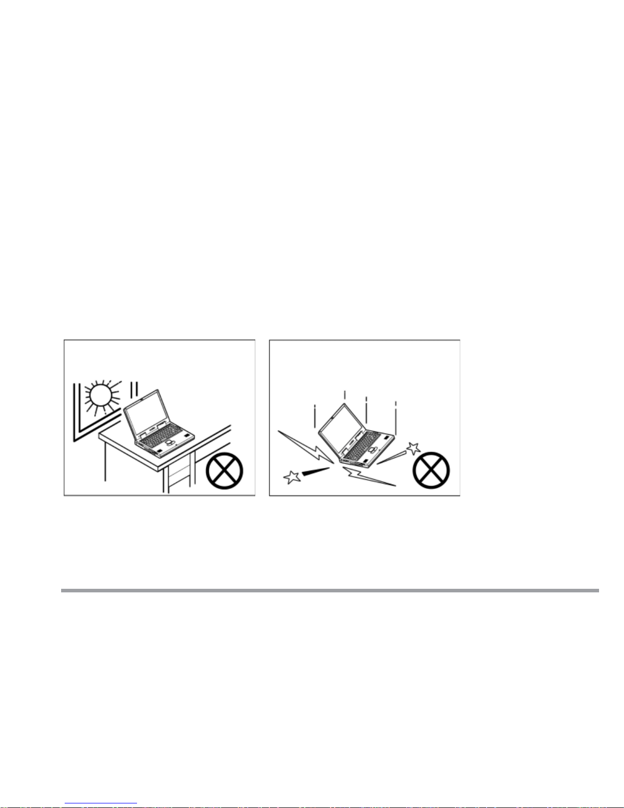
Handling the Computer
Do not expose it to excessive heat or
direct sunlight.
Do not expose your notebook computer to any shock or vibration.
Page 7
vi
User’s Manual
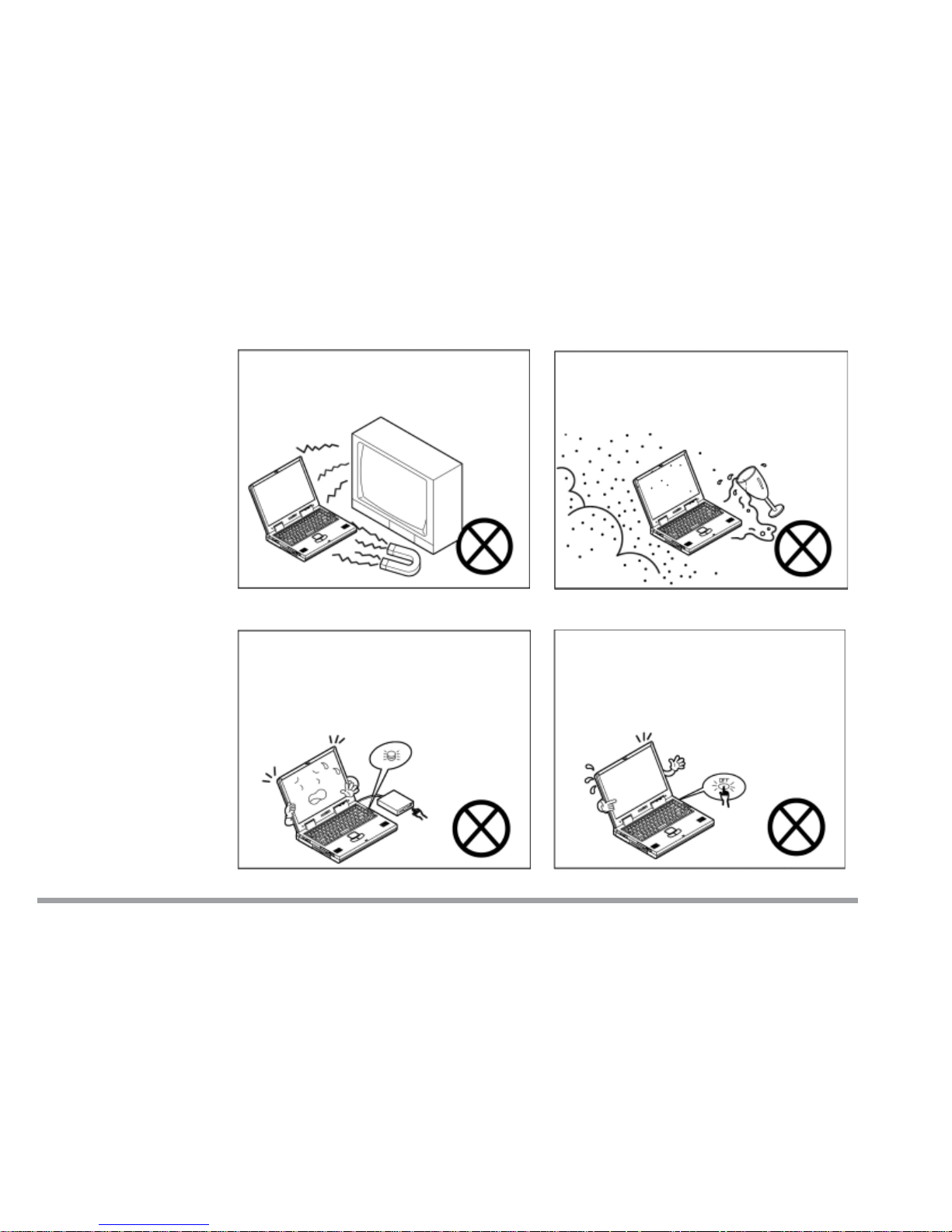
Do not expose it to strong magnetic
fields.
Do not leave it in a place where
foreign matter or moisture may
affect the system.
Do not turn off any peripheral
devices when the computer is on.
Do not turn off the power until you
properly shutdown all programs.
Page 8
vii
Preface
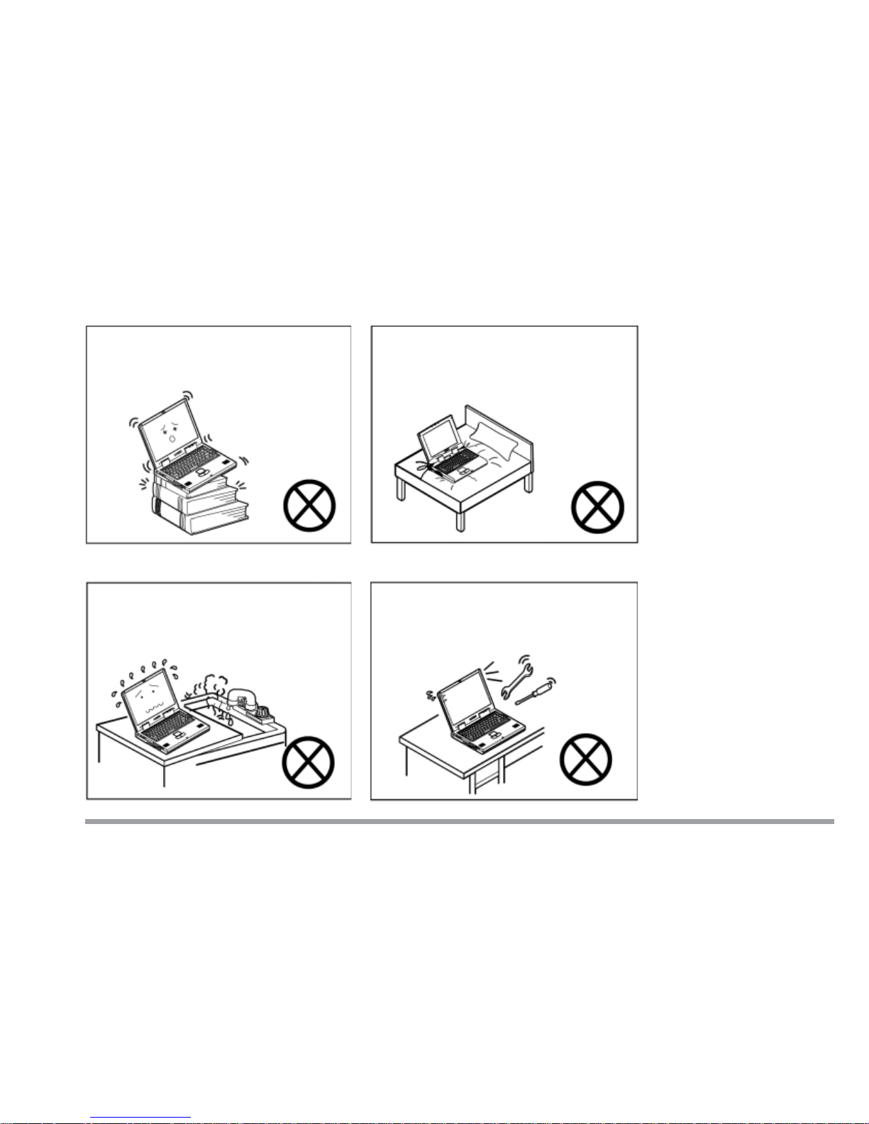
Do not place the computer on an
unstable surface.
Do not place the computer on any
surface which will block the vents.
Don’t use or store the computer in
a humid environment.
Do not disassemble the computer
by yourself.
Page 9
viii
User’s Manual
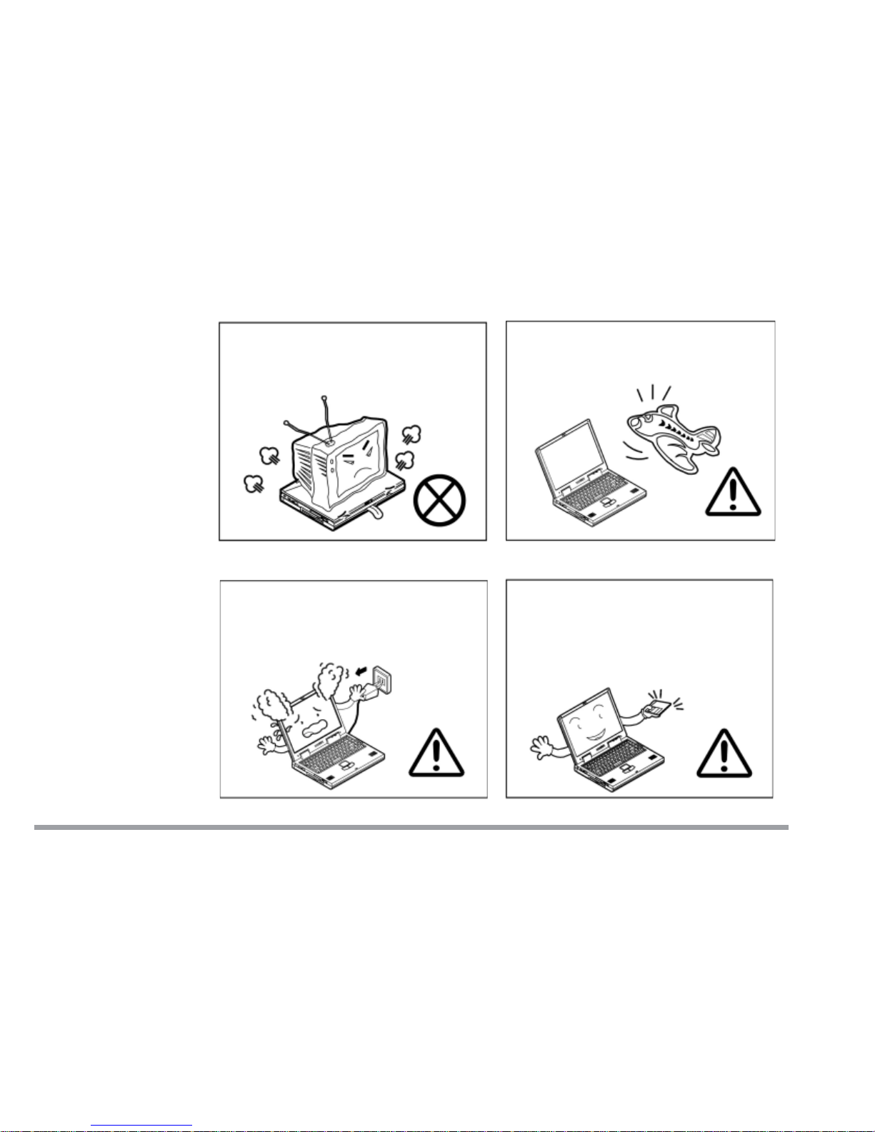
Do not place anything heavy on the
computer.
When traveling by air, follow the
airline’s instructions for in-flight
use.
If there is an unusual odor, heat or
smoke coming from your computer,
unplug the cord.
Perform routine maintenance on
your computer.
Page 10
ix
Preface
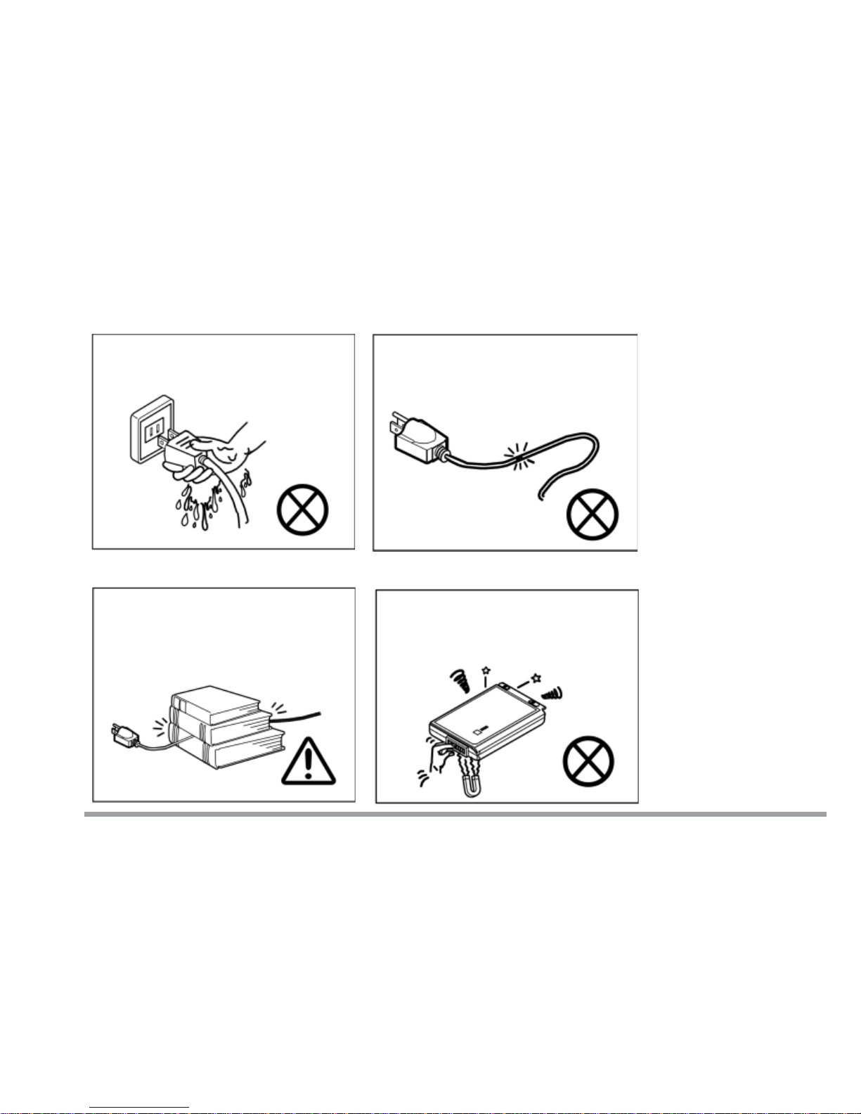
Handling of the Power Cord & Battery
Do not plug in the power cord if you
are wet.
Do not use the power cord if it is
broken.
Do not place heavy objects on the
power cord.
Do not touch the battery contacts
with your hands or any metal
objects.
Page 11
x
User’s Manual
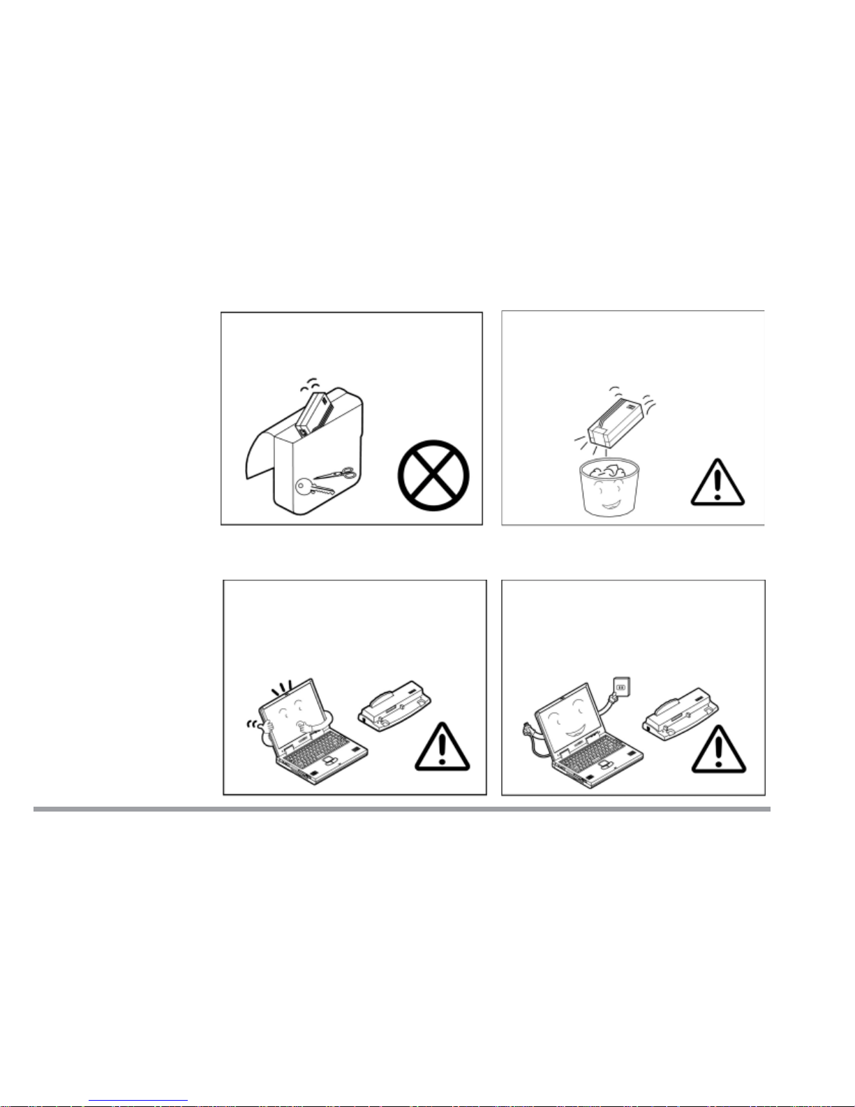
Handling Peripheral Devices
Use only approved brands of
peripheral devices.
Unplug the power cord before
attaching any peripheral devices.
Keep the battery away from
metal appliances.
Affix tape to the battery contacts
before diposing of the battery.
Page 12
xi
Preface
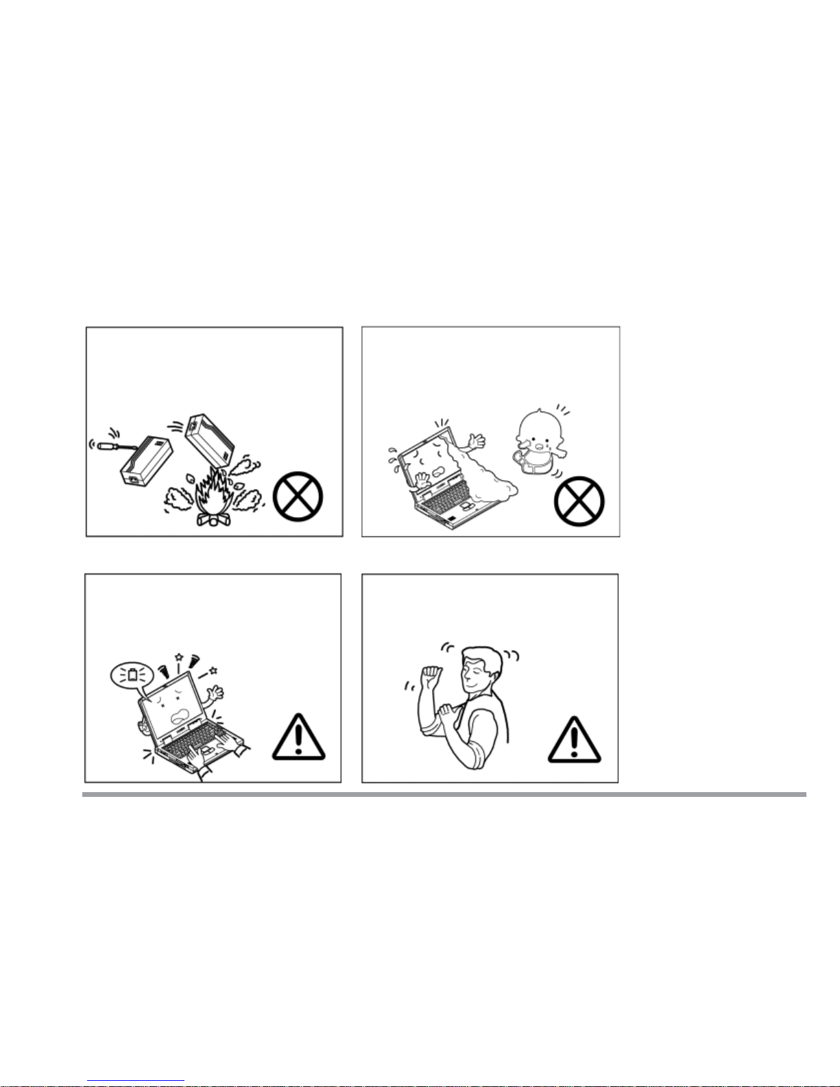
Other Reminders
Remember to periodically save your
data. Data may be lost if the battery is depleted.
Take periodic breaks if you are
using the computer for long periods of time.
Do not throw the computer or
accessories into a fire.
Do not touch the poisonous
liquid if the LCD panel breaks.
Page 13
xii
User’s Manual
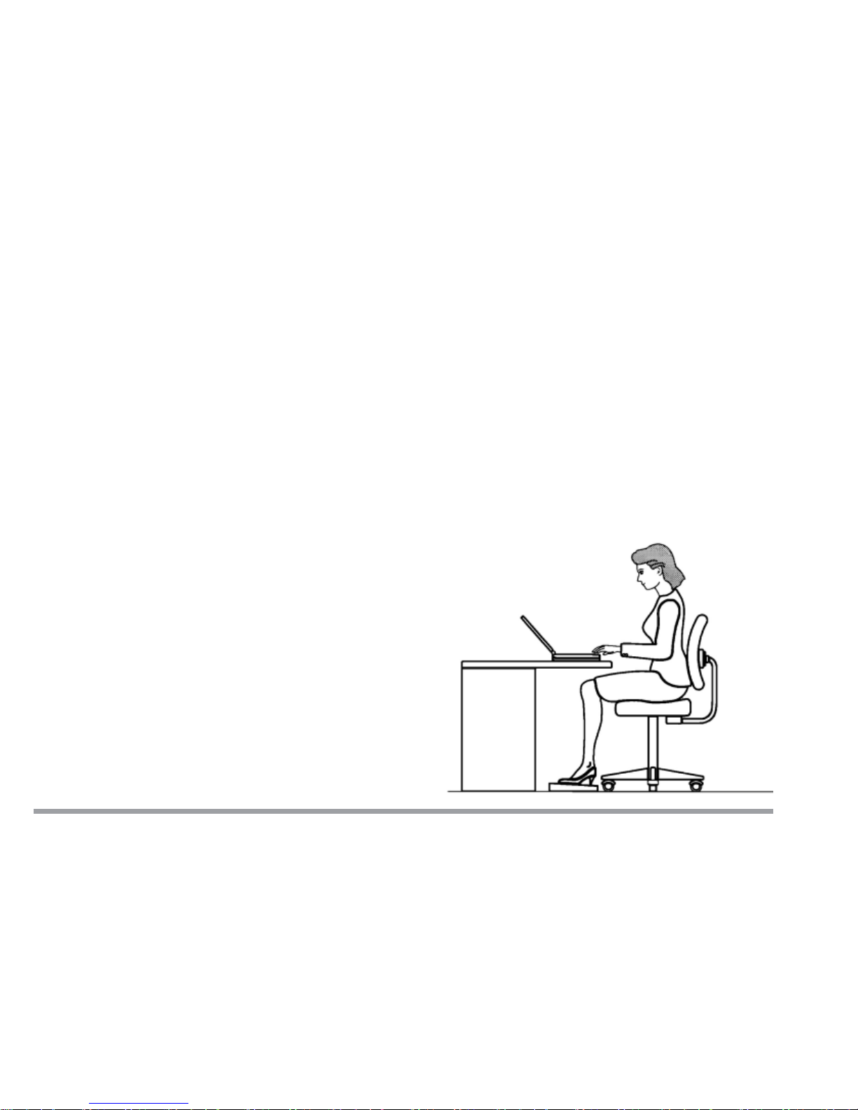
Developing Good Work Habits
Developing good work habits is important if you need to work in front of the
computer for long periods of time. Improper work habits can result in discomfort or serious injury from repetitive strain to your hands, wrists or other joints.
The following are some tips to reduce the strain:
– Adjust the height of the chair and/or desk so that the keyboard is at or
slightly below the level of your elbow. Keep your forearms, wrists, and
hands in a relaxed position.
– Your knees should be slightly higher than your hips. Place your feet flat
on the floor or on a footrest if necessary.
– Use a chair with a back
and adjust it to support
your lower back comfortably.
– Sit straight so that your
knees, hips and elbows
form approximately 90
degree angles when you
are working.
Page 14

xiii
Preface
Remember to:
– Alter your posture frequently.
– Stretch and exercise your body several times a day.
– Take periodic breaks when you work at the computer for long periods of
time. Frequent and short breaks are better than fewer and longer
breaks.
Lighting
Proper lighting and comfortable display viewing angle can reduce eye strain
and muscle fatigue in your neck and shoulders.
– Position the display to avoid glare or reflections from overhead lighting
or outside sources of light.
– Keep the display screen clean and set the brightness and contrast to
levels that allow you to see the screen clearly.
– Position the display directly in front of you at a comfortable viewing
distance.
– Adjust the display viewing angle to find the best position.
Page 15

xiv
User’s Manual
Contents
Chapter 1. Getting to Know Your Computer
Quick Start Guide ............................................................................................... 1-2
Top View with LCD Display Closed................................................................... 1-3
Top View with Display Open.............................................................................. 1-4
LCD Display.................................................................................................. 1-5
Microphone ................................................................................................... 1-5
LED Status Indicators ................................................................................. 1-5
Three Hot-key Buttons................................................................................. 1-5
Power Button ................................................................................................ 1-5
Keyboard ....................................................................................................... 1-6
Stereo Speakers ............................................................................................ 1-6
TouchPad and Buttons ................................................................................. 1-6
LED Power Indicators.................................................................................. 1-6
Right Side View .................................................................................................. 1-7
5.25" CD Device ............................................................................................ 1-7
Vent............................................................................................................... 1-7
Security Slot.................................................................................................. 1-7
Attaching a Security Lock ...................................................................... 1-8
Rear View............................................................................................................ 1-9
DC-in Jack..................................................................................................... 1-9
PS/2 Type Port .............................................................................................. 1-9
Parallel Port .................................................................................................. 1-9
Page 16

xv
Preface
Phone Jack.................................................................................................. 1-10
Vent............................................................................................................. 1-10
External Monitor (CRT) Port ..................................................................... 1-10
Dual USB Ports .......................................................................................... 1-10
S-Video Connector ...................................................................................... 1-10
IEEE 1394 Port .......................................................................................... 1-11
LAN Jack .................................................................................................... 1-11
Left Side View................................................................................................... 1-12
Microphone-in Jack .................................................................................... 1-12
Speaker-out Jack ........................................................................................ 1-12
Audio Volume Control ................................................................................ 1-13
PC Card Slot............................................................................................... 1-13
Infrared Port............................................................................................... 1-13
3.5" FDD (Floppy Disk Drive)..................................................................... 1-13
Bottom View...................................................................................................... 1-14
RAM Cover ................................................................................................. 1-14
Battery Pack Cover .................................................................................... 1-14
Chapter 2. Using the Computer
The Power Sources ............................................................................................. 2-2
AC Adapter ................................................................................................... 2-2
Battery .......................................................................................................... 2-3
Recharging by AC Power....................................................................... 2-4
Proper Handling of the Battery Pack.................................................... 2-4
Turning on the Computer .................................................................................. 2-5
LED Indicators ............................................................................................. 2-5
LED Power Indicators............................................................................ 2-6
Page 17

xvi
User’s Manual
LED Status Indicators ........................................................................... 2-7
The Hard Disk Dr ive (HDD)............................................................................... 2-8
Removing the HDD Module ......................................................................... 2-8
Inserting the HDD Module ........................................................................ 2-10
Replacing the HDD..................................................................................... 2-11
The Floppy Disk Drive (FDD) .......................................................................... 2-13
Inserting and Removing Diskettes............................................................ 2-13
The CD Device .................................................................................................. 2-14
Loading CDs or DVDs ...................................................................................... 2-14
Handling CDs or DVDs .............................................................................. 2-15
The PC Card Slot.............................................................................................. 2-16
Inserting PC Cards .................................................................................... 2-16
Removing PC Cards ................................................................................... 2-16
PC Card Problem in Windows 98 .............................................................. 2-17
Hot Keys ............................................................................................................ 2-18
Three Hot-Key Buttons .............................................................................. 2-18
Programming the Hot Keys ....................................................................... 2-19
Function Keys................................................................................................... 2-20
The Numeric Keypad........................................................................................ 2-21
Chapter 3. Power and Battery Information
Power Management ............................................................................................ 3-1
Advanced Configuration and Power Interface (ACPI) ............................... 3-1
Advanced Power Management (APM 1.2) .................................................. 3-1
Conserving Power through Individual Components: ................................. 3-2
Hard Disk Standby ................................................................................. 3-2
Monitor Standby..................................................................................... 3-2
Page 18

xvii
Preface
Conserving Power throughout the Whole System:..................................... 3-2
Suspend and Resume ................................................................................... 3-2
A: Standby ............................................................................................... 3-2
B: Hibernate............................................................................................ 3-3
Setting the Power Management Functions ................................................ 3-4
Creating a Partition on Your Hard Drive ............................................. 3-5
Battery Information ........................................................................................... 3-6
New Battery:................................................................................................. 3-6
Battery Life:.................................................................................................. 3-6
Battery FAQ ................................................................................................. 3-6
Conserving Battery Power ........................................................................... 3-7
Removing the Battery........................................................................................ 3-8
Chapter 4. Upgrading the Computer
Upgrading the Memory...................................................................................... 4-2
A: Removing a Memory Module .................................................................. 4-3
B: Installing a Memory Module................................................................... 4-5
C: Setting the SW6 Jumper Switch ............................................................. 4-6
Upgrading the Processor.................................................................................... 4-8
Upgrading the Hard Disk................................................................................... 4-8
Chapter 5. BIOS Utilities
Power On Self Test (POST) ................................................................................ 5-2
POST Message: Normal Operation.............................................................. 5-2
POST Message: Error Detected ................................................................... 5-3
System Configuration Utility ............................................................................ 5-4
Page 19

xviii
User’s Manual
Information in the System
Configuration Utility (SCU) ........................................................................ 5-4
Initiating the System Configuration Utility............................................... 5-5
Working with the Menu Bar........................................................................ 5-6
Working with the Pull-down Menu ....................................................... 5-7
System Configuration Utility Options ........................................................ 5-8
Startup Menu .......................................................................................... 5-8
Memory Menu ....................................................................................... 5-11
Disks Menu ........................................................................................... 5-12
Components Menu ................................................................................ 5-13
Power Menu .......................................................................................... 5-16
Exit Menu ............................................................................................. 5-18
SCU Screen Samples .................................................................................. 5-19
Startup Screen...................................................................................... 5-19
Memory Screen ..................................................................................... 5-19
Disks Screen.......................................................................................... 5-20
Components Screen .............................................................................. 5-20
Power Screen ........................................................................................ 5-21
Exit Screen ............................................................................................ 5-21
Chapter 6. Driver Installation
Before Installing Windows ................................................................................. 6-2
Partitioning the HDD............................................................................. 6-2
Formatting the HDD .............................................................................. 6-2
Installing Windows 98 SE (for reference only) ................................................. 6-3
Installing Windows Me (for reference only) ...................................................... 6-4
Installing Windows 2000 (for reference only) ................................................... 6-5
Page 20

xix
Preface
Installing Drivers in Windows 98 SE ................................................................ 6-7
Step 1: Installing the Audio Driver ............................................................. 6-7
Step 2: Installing the Video Driver.............................................................. 6-8
Step 3: Installing the Hot Key Driver.......................................................... 6-8
Step 4: Installing the LAN Driver ............................................................... 6-9
Step 5: Installing the PCMCIA Driver (Optional)...................................... 6-9
Step 6: Installing the Modem Driver (Optional) ....................................... 6-10
Installing Drivers in Windows Me................................................................... 6-12
Step 1: Installing the Audio Driver ........................................................... 6-12
Step 2: Installing the Video Driver............................................................ 6-13
Step 3: Installing the Hot Key Driver........................................................ 6-13
Step 4: Installing the LAN Driver ............................................................. 6-14
Step 5: Installing the Modem Driver (Optional) ....................................... 6-14
Installing Drivers in Windows 2000................................................................ 6-16
Step 1: Installing the SiSIDE Utility ........................................................ 6-16
Step 2: Installing the Audio Driver ........................................................... 6-16
Step 3: Installing the Video Driver............................................................ 6-16
Step 4: Installing the Hot Key Driver........................................................ 6-17
Step 5: Installing the LAN Driver ............................................................. 6-17
Step 6: Installing the Modem Driver (Optional) ....................................... 6-18
Installing Drivers in Windows NT4.0 ............................................................. 6-20
Step 1: Installing the Audio Driver ........................................................... 6-20
Step 2: Installing the Video Driver............................................................ 6-20
Step 3: Installing the Hot Key Driver........................................................ 6-21
Step 4: Installing the LAN Driver ............................................................. 6-21
Step 5: Installing the Modem Driver (Optional) ....................................... 6-22
Page 21

xx
User’s Manual
Chapter 7. Troubleshooting
Audio ............................................................................................................. 7-2
Battery .......................................................................................................... 7-2
Boot Password............................................................................................... 7-4
CD.................................................................................................................. 7-4
Floppy Disk Drive (FDD).............................................................................. 7-6
Hard Disk Drive (HDD) ................................................................................ 7-7
Hardware Installation .................................................................................. 7-7
LCD Panel ..................................................................................................... 7-8
Microphone-in Jack ...................................................................................... 7-8
Memory Module............................................................................................ 7-9
PC Card ....................................................................................................... 7-10
Power........................................................................................................... 7-10
Printer......................................................................................................... 7-11
Appendix A. Specifications
Glossary
Page 22
1 - 1
Getting to Know Your Computer
1
Chapter 1. Getting to Know Your Computer
In this chapter you will become familiar with the basic functions and components of your notebook computer and possibilities for expansion.
This chapter includes:
• Quick start guide
• Views
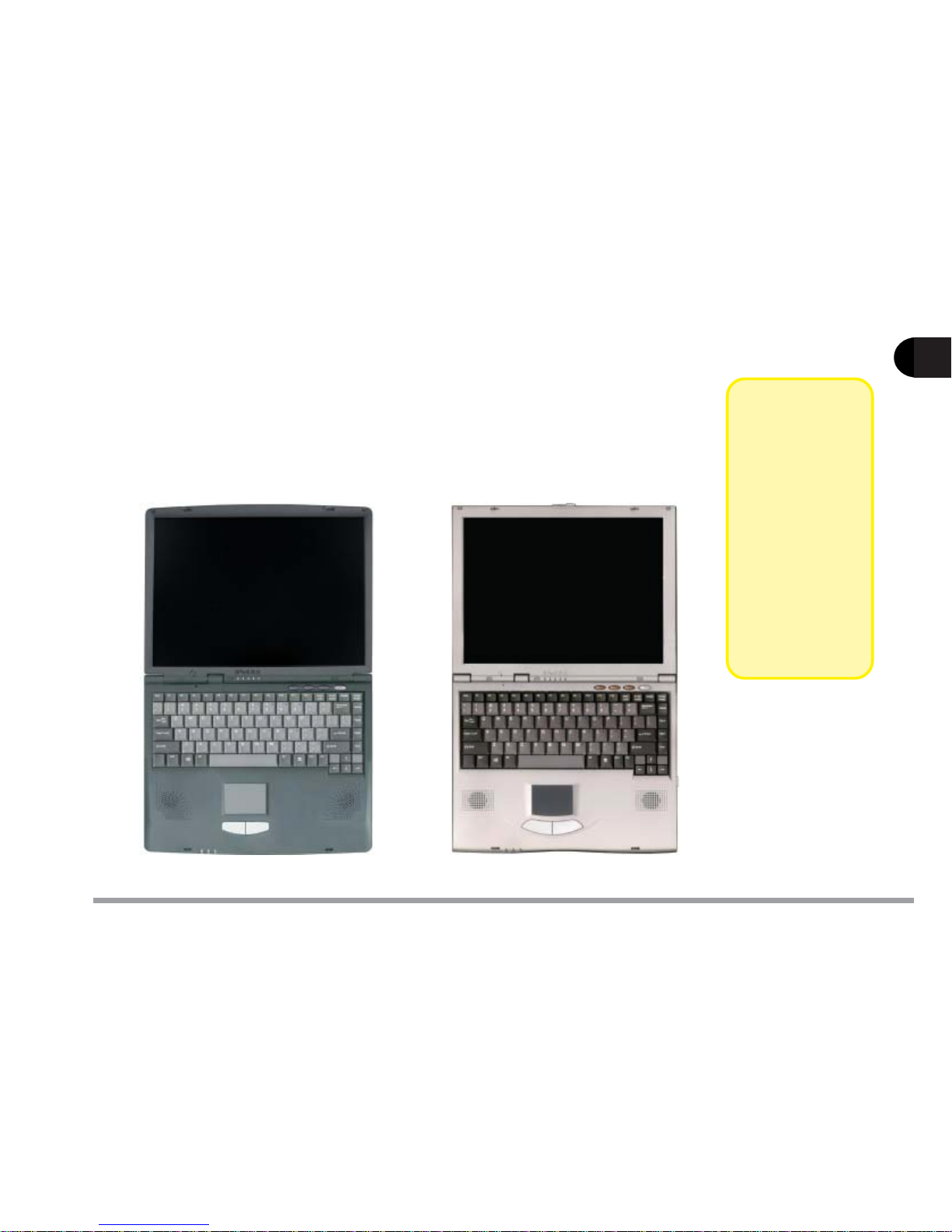
Model A Model B
!!
!!
!
Note
This manual
refers to the two
notebook models pictured on
this page.
The models
vary slightly in
external design.
Photos used
throughout this
manual are of
Model A.
Page 23

1 - 2
1
User’s Manual
Quick Start Guide
This quick start guide assumes that you’re already familiar with notebook computers and can tell at a glance what and where all the key components are.
If you’re not that comfortable with this sort of device, take a look at the following
pages for an overview of the system.
In any case, you should review these steps, before you take any action. If you
aren’t sure about one of the procedures, check the relevant chapter before continuing.
Unless you have to install an operating system, your computer is ready to work
right out of the box.
But, before you begin, follow the safety instructions in the Preface, especially
the instruction on placement.
1. Remove all packing materials, CDs/DVDs, floppy disks and any PC Cards.
2. Securely attach any peripherals you want to use with the notebook (e.g.
mouse and keyboard) to their ports.
3. Attach the AC adapter to the DC-in jack on the computer’s rear, plug the
AC power cord into an outlet and then connect the AC power cord to the AC
adapter.
4. Raise the lid/LCD to a comfortable viewing angle (page 1-3).
5. Push the power button to turn “on”.
!!
!!
!
Note
Be sure to keep
the packing
materials in a
safe place in
case you need
them for shipping or longterm storage.
!!
!!
!
Note
Devices which
connect to the
USB and
IEEE 1394
ports can be
connected after
Windows is up
and running.
All other devices must be
connected
before you turn
on the system.
Page 24
1 - 3
Getting to Know Your Computer
1
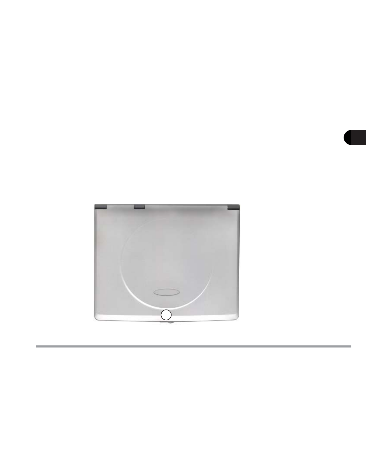
Top View with LCD Display Closed
To open the LCD display:
1) Place the computer on a stable surface.
2) Move the cover latch to the right to release the top cover.
3) Lift the top cover to reveal the LCD panel and keyboard.
4) Adjust the LCD panel to a comfortable viewing angle.
1. Cover Latch
1
figure 1-1
Page 25
1 - 4
1
User’s Manual
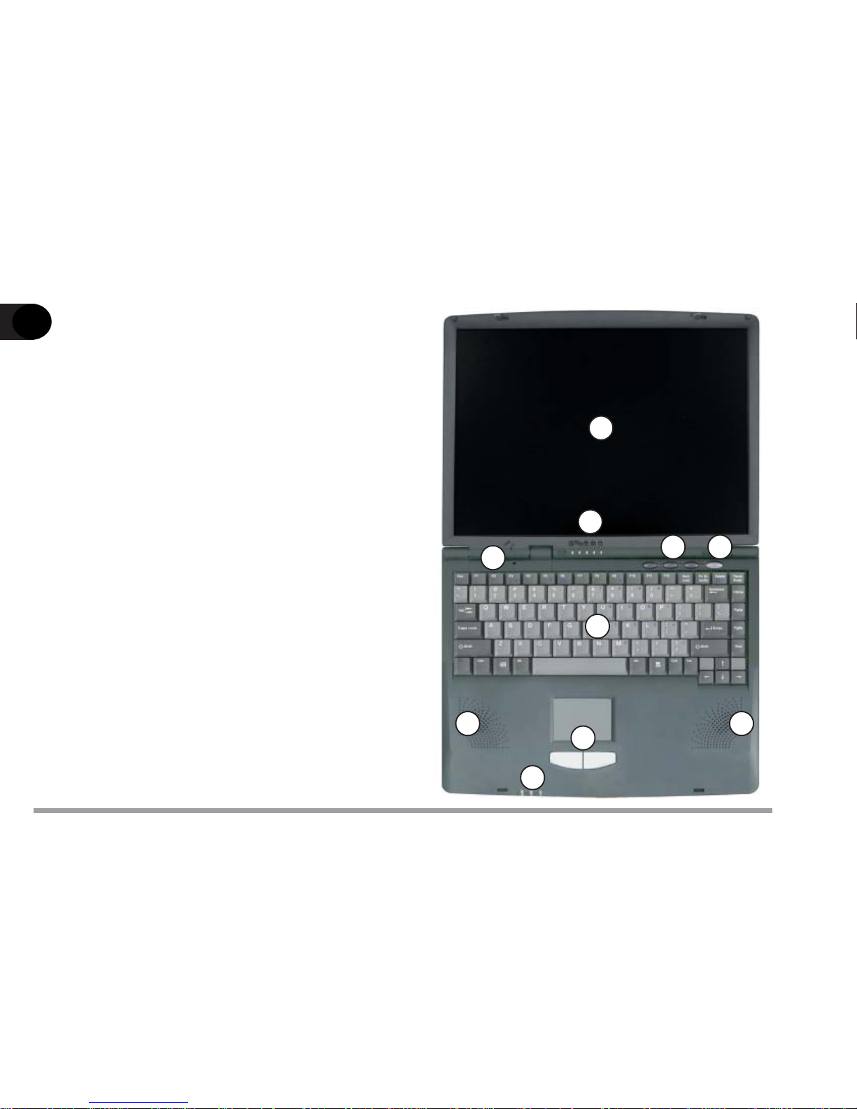
Top View with Display
Open
1. LCD Display
2. Microphone (built-in)
3. LED Status Indicators
4. Three Hot-Key Buttons
5. Power Button
6. Keyboard
7. Stereo Speakers
8. TouchPad and Buttons
9. LED Power Indicators
1
2
3
4
6
7
8
9
5
7
figure 1-2
Page 26
1 - 5
Getting to Know Your Computer
1
LCD Display
The Notebook comes with a TFT LCD (Liquid Crystal Display) display.
Depending on the model and configuration you have purchased, the display can be either a 13.3” or 14.1” XGA TFT color panel.
Microphone
Record on your notebook computer with this built-in microphone.
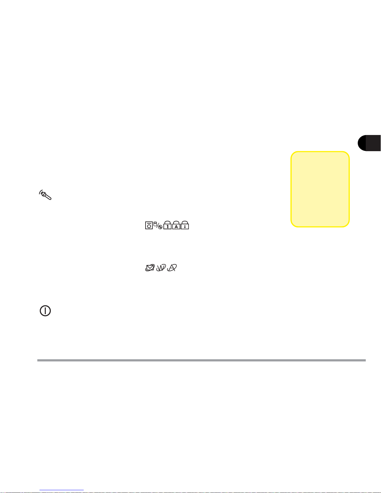
LED Status Indicators
Display the system's operational status. Refer to Chapter 2 for more
information.
Three Hot-key Buttons
Three hot keys give you easy access to the Internet, e-mail and an application of your choice. To learn how to set the buttons refer to Chapter 2.
Power Button
Press this button to turn your notebook computer on or off. The Power
Button can also be used as a Suspend/Resume button when pressed less
than four seconds (if configured appropriately in the System Configuration Utility, refer to Chapter 5 for more details).
!!
!!
!
Note
After turning
the computer off
wait at least 5
seconds before
turning it on
again.
Page 27

1 - 6
1
User’s Manual
Keyboard
An A4-Size Win98 keyboard with an embedded numeric keypad. It has
many of the same features as a full-sized desktop keyboard and can easily
be replaced with a non-English keyboard should you desire.
Stereo Speakers
Two built-in speakers provide rich, stereo sound.
TouchPad and Buttons
The pointing device features a sensitive glide pad for precise movements.
It functions the same way as a two-button mouse: the right TouchPad
button is the same as the right mouse button; the left TouchPad button is
the same as the left mouse button.
LED Power Indicators
Display the current power source and power source status of the computer.
For more information please refer to Chapter 2.
Page 28
1 - 7
Getting to Know Your Computer
1
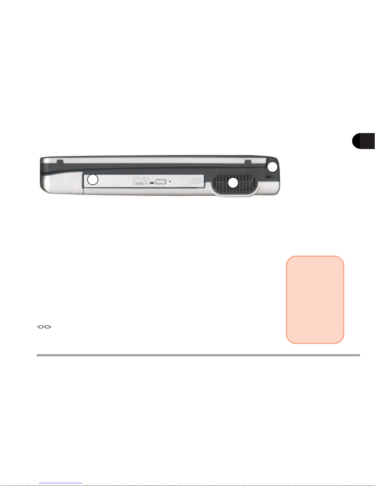
5.25" CD Device
Depending on the configuration you purchased, your notebook may come
with one of the following 12.7mm CD devices: 24X-speed CD-ROM drive,
8X-speed DVD-ROM drive, CD-RW drive (20X Read, 8X Write) or DVDROM+CD-RW combo drive.
Vent
Enables airflow to prevent the notebook from overheating.
Security Slot
To prevent possible theft a lock can be attached to this slot. Locks can be
purchased at any computer store.
Right Side View
1. 5.25” CD Device 2. Vent 3. Security Slot
figure 1-3
3
2
1
!!
!!
!
Warning
To prevent your
computer from
overheating,
make sure
nothing blocks
the vent while
the computer is
in use.
Page 29
1 - 8
1
User’s Manual
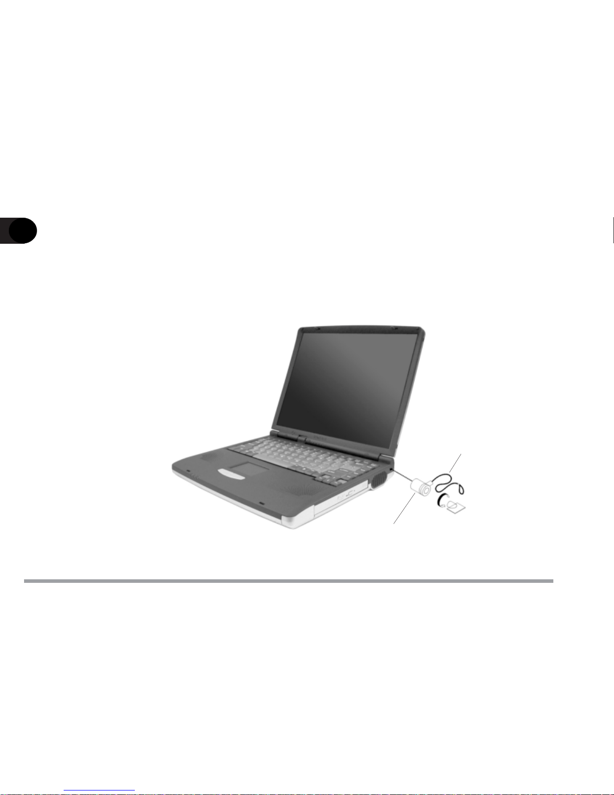
Attaching a Security Lock
To install the security lock, wrap the cable around a desk or other immovable
object, then insert the locking device into the slot located on the right side of the
computer.
figure 1-4
Security Lock
Security Lock Cable
Page 30
1 - 9
Getting to Know Your Computer
1
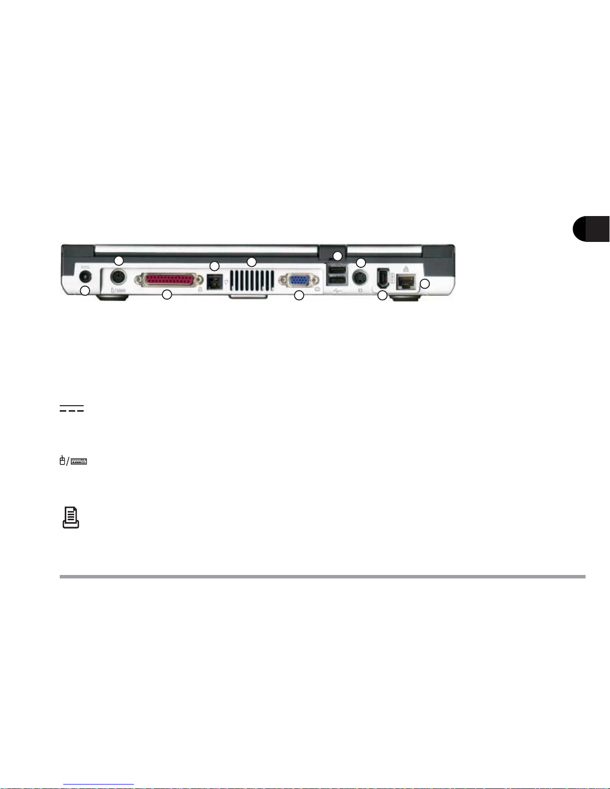
Rear View
1. DC-in Jack
2. PS/2 Type Port
3. Parallel Port
4. Phone Jack
5. Vent
6. External Monitor
(CRT) Port
7. Dual USB Ports
8. S-Video Connector
9. IEEE 1394 Port
10. LAN Jack
DC-in Jack
Plug the supplied AC adapter into this jack to power your notebook.
PS/2 Type Port
To connect an external PS/2 type mouse or keyboard.
Parallel Port
This parallel port supports ECP (Extended Capabilities Port) and EPP
(Enhanced Parallel Port) 1.7/1.9 modes.
figure 1-5
1
2
3
4
5
6
7
8
9
10
Page 31

1 - 10
1
User’s Manual
Phone Jack
Supports the optional modem module.
Vent
Enables airflow to prevent the notebook from overheating.
External Monitor (CRT) Port
Connect an external CRT monitor to this port to allow simultaneous display on the LCD display and external CRT monitor.
Dual USB Ports
A hardware interface for low-speed peripherals such as the keyboard,
mouse, joystick, scanner, printer and telephony devices. It allows everything to be plugged in and unplugged without turning the system off
S-Video Connector
Connect your television to your computer and view DVD’s, VCD’s or anything else your computer can display. You will need an S-Video cable to
make the connection which is easily found at any audio or computer store.
!!
!!
!
Warning
To prevent your
computer from
overheating,
make sure
nothing blocks
the vent while
the computer is
in use.
Page 32

1 - 11
Getting to Know Your Computer
1
IEEE 1394 Port
Allows high speed connection to various peripheral devices, such as an
external disk drive or a digital camera.
LAN Jack
Supports the integrated LAN function.
!!
!!
!
Note
Your notebook
will only accept
IEEE 1394
devices which
have their own
power source.
Page 33

1 - 12
1
User’s Manual
Microphone-in Jack
A microphone can be connected to your notebook via this jack. You can
also use this for S/PDIF (Sony/Philips Digital Interface Format) output,
which allows you to connect your DVD-capable PC to a Dolby AC-3 compatible receiver giving you surround sound. To switch from microphonein to S/PDIF output or S/PDIF output to microphone-in, you will need to
use the SCU. Refer to the Startup Menu in Chapter 5 for information.
Speaker-out Jack
Headphones or speakers can be connected through this jack.
Left Side View
1. Microphone-in Jack
2. Speaker-out Jack
3. Audio Volume Control
4. PC Card Slot
5. Infrared Port
6. 3.5” FDD (Floppy Disk Drive)
1 2
3
4
5
6
figure 1-6
!!
!!
!
Note
The S/PDIF
output feature
is available only
in Windows 98
and Windows
Me.
Refer to Chapter 6 for installation instructions and settings.
Page 34

1 - 13
Getting to Know Your Computer
1
Audio Volume Control
Adjust the audio volume with this knob. Audio volume can also be adjusted in the operating system.
PC Card Slot
A Type-II PC card slot which also supports CardBus mode. Refer to
Chapter 2 for more information on the PC Card slot.
Infrared Port
Allows wireless communications with an infrared-compatible device. The
Infrared port supports IrDA (HPSIR) 1.1, FIR and ASKIR (Sharp standard) modes. For further information, please refer to the manual of the
infrared device you wish to connect.
3.5" FDD (Floppy Disk Drive)
A 3.5”, 3-mode, 1.44 MB fixed floppy disk drive. For more information on
using the floppy disk drive, please refer to Chapter 2.
Page 35

1 - 14
1
User’s Manual
Bottom View
RAM Cover
The cover secures the installed RAM modules. For further information on
removing or inserting the RAM modules, please refer to Chapter 4.
Battery Pack Cover
The cover secures the battery pack in its bay.
1. RAM Cover 2. Battery Cover
1
figure 1-7
2
Page 36

2 - 1
Using the Computer
2
Chapter 2. Using the Computer
Your notebook computer can be used almost anywhere, in the home, office, or on
the road. To learn more about your computer, please read this chapter.
This chapter includes:
– The Power Sources
– Turning on the Computer
– The Hard Disk Drive
– The Floppy Disk Drive
– The CD Device
– The PC Card Slot
– The Hot Keys
– The Numeric Keypad
Page 37

2 - 2
User’s Manual
2
figure 2-1
The Power Sources
The computer can be powered by either an AC adapter or a battery pack depending on where you want to use it.
AC Adapter
Use only the AC adapter that comes with your computer. An incorrect type of
AC adapter will cause damage to the computer and its components.
1) Plug the AC adapter cord into the DC-in jack on the rear panel of the computer.
2) Plug the power cord into a
properly grounded
outlet.
3) Connect the AC
adapter with the
power cord.
Page 38

2 - 3
Using the Computer
2
Battery
The battery allows you to use your notebook computer while you are on the
road or an electrical outlet is unavailable. Battery life varies depending on the
applications and the configuration you're using. To increase battery life, let the
battery discharge completely before recharging.
We recommend leaving the battery inside the notebook at all times. For more
information on the battery, please refer to Chapter 3.
1. Battery Cover
figure 2-2
!!
!!
!
Note
Don’t remove
the battery pack
from the computer unless it
is damaged and
needs to be
replaced.
1
Page 39

2 - 4
User’s Manual
2
Recharging by AC Power
The battery pack automatically recharges when plugged into an electrical outlet. If the computer is powered on and in use it will take several hours to fully
recharge the battery. When the computer is turned off but plugged into an
electrical outlet, battery charge time is less. (Refer to LED Power Indicators in
this chapter for information on the battery charge status.)
Proper Handling of the Battery Pack
- DO NOT disassemble the battery pack under any circumstances.
- DO NOT expose the battery to fire or high temperatures, it may explode.
- DO N OT connect the metal terminals (+, -) together . (For more information on how
to maintain the battery pack, refer to Chapter 3.)
Page 40

2 - 5
Using the Computer
2
Power
Button
figure 2-3
Turning on the Computer
Now you are ready to begin using your new notebook computer. To turn it on
simply press the power button on the top right of the front panel (figure 2-3) .
The power button can also be used as a Suspend/Resume hot-key button if
pressed less than four seconds and appropriately configured in the SCU.
(Please refer to Chapter 5, BIOS Utilities, for
more information.)
LED Indicators
There are two sets of LED indicators (LED Power Indicators and LED Sta-
tus Indicators) on your computer that will display helpful information about
the current status of the computer.
Page 41

2 - 6
User’s Manual
2
LED Power Indicators
table 2-1
LED Power Indicatorsfigure 2-4
!!
!!
!
Note
When the battery is critically
low, immediately connect
the AC adapter
to the computer
or save your
work; otherwise,
the unsaved
data will be lost
when power is
depleted.
nocI
roloC noitpircseD
neerG.nodenrutsiretupmocehT
neerGgniknilB
dnepsusderugifnocehtderetnesahmetsysehT
.edom
wolleY.llufsirewopyrettabronideggulpsirewopCA
wolleYgniknilB.degrahcgniebsiyrettabehT
thgiloN
sirewopyrettabrodesugniebsirewopCA
.lamron
wolleYgniknilBwolyllacitircsirewoPyrettaB
Page 42

2 - 7
Using the Computer
2
LED Status Indicators
Once your computer is on and in use, the
LED status indicators will display the
system's operational status.
figure 2-5
table 2-2
nocI roloC noitpircseD
neerG.desseccagniebsievirdksidyppolF
neerG.desseccagniebsiecivedDC/ksiddrahehT
neerG.detavitcasikcoLmuN
neerG.detavitcasikcoLspaC
neerG.detavitcasikcoLllorcS
!!
!!
!
Note
To enable/
disable the
Scroll Lock
feature, press
the Fn and Scr
Lk key simultaneously.
Page 43

2 - 8
User’s Manual
2
The Hard Disk Drive (HDD)
The hard disk drive is used to store your data internally in the notebook computer. It is mounted in a removable case and can be taken out to accommodate
other 2.5” IDE hard disk drives with a height of 9.5 mm or 12.7 mm. The system supports DMA mode 2, PIO mode 4, and ATA-33/ATA-66/ATA-100 IDE
HDDs.
Removing the HDD Module
1) Turn off the computer.
2) Press the four keyboard latches at the top of
the keyboard to elevate the
keyboard from its normal
position (figure 2-6)
!!
!!
!
Warning
Before remov-
ing the HDD,
please check
with your
dealer to find
out if this will
VOID your
warranty.
figure 2-6
Page 44

2 - 9
Using the Computer
2
2
3
figure 2-8
1
1. HDD
2. HDD Tab
3. HDD Connector
figure 2-7a
""
""
"
""
""
"
figure 2-7b
A
C
B
3) Carefully raise and set the keyboard aside and
locate the HDD module (figure 2-7a).
4) Unscrew the 3 screws (A, B, C) holding the
HDD module on the mainboard (figure 2-7b) .
5) Lift the HDD module out of the computer by
pulling on the HDD tab (figure 2-8).
Page 45

2 - 10
User’s Manual
2
Inserting the HDD Module
(with no HDD module currently installed)
1) Place the HDD module into the computer in its appropriate spot, making
sure to align the HDD connector with the socket on the mainboard (figure
2-9).
2) Connect the HDD connector securely to the mainboard by gently pressing
the HDD module on to the mainboard.
3) Insert and tighten the 3 screws which hold the HDD module on the
mainboard.
4) Reinstall the keyboard.
1. HDD
2. HDD Tab
3. HDD Connector
4. HDD Socket on Mainboard.
figure 2-9
1
2
4
3
Page 46

2 - 11
Using the Computer
2
Connector Board
HDD
HDD Case
figure 2-10
Replacing the HDD
1) Remove the HDD module (refer to Removing the HDD Module on
pages 2-8 to 2-9 for details).
2) Remove the two screws on the HDD connector board.
3) Gently disconnect the HDD connector board from the HDD being careful
not to bend any pins.
4) Remove the two screws on each
side of the case.
5) Slowly remove the HDD from
the case.
6) Place a new HDD into the
case.
7) Hold the HDD firmly in
place with two screws on
each side.
!!
!!
!
Warning
Before remov-
ing the HDD,
please check
with your
dealer to find
out if this will
VOID your
warranty.
Page 47

2 - 12
User’s Manual
2
8) Attach the HDD connector board to the HDD being careful not to bend any
pins.
9) Screw the HDD connector board on to the HDD.
10) Place the HDD module into the computer (refer to Inserting the HDD
Module on page 2-10 for details).
Page 48

2 - 13
Using the Computer
2
Eject Button
figure 2-11
The Floppy Disk Drive (FDD)
The computer is equipped with a fixed 1.44 MB, 3.5” floppy disk drive module.
It is usually designated drive A by default and can be used as a boot device if
properly set in the SCU (please refer to Chapter 5, BIOS Utilities).
Inserting and Removing Diskettes
When using the floppy drive, always insert your
floppy diskette with the label-side facing up. To
remove the inserted diskette, press the eject
button on the top-right corner of the floppy
drive.
Page 49

2 - 14
User’s Manual
2
The CD Device
The CD device can be a CD-ROM, DVD-ROM, CD-RW or DVD-ROM+CD-RW
combo module depending on the configuration you purchased. It is usually
labeled drive D and may be used as a boot device if properly set in the SCU
(please refer to Chapter 5, BIOS Utilities).
Loading CDs or DVDs
To insert a CD/DVD, press the open button and carefully place a disc onto the
disc tray with label-side facing up (see below). Push the disc tray in and you are
ready to start. The busy indicator will light up while data is being accessed or
while an audio CD is playing. If power is unexpectedly interrupted, insert an
object such as a straightened paper clip into the emergency eject hole to open
the tray.
1. Disc Tray
2. Busy Indicator
3. Open Button
4. Emergency Eject Hole
!!
!!
!
Warning
When manually
ejecting a CD/
DVD, DO NOT
use a sharpened
pencil or similar object that
may break and
become lodged
in the hole.
3
1
2
4
CD Tray
2
4
3
figure 2-12
DVD Tray
Page 50

2 - 15
Using the Computer
2
Handling CDs or DVDs
Proper handling of your CDs/DVDs will prevent them from being damaged.
Please follow the advice listed below to make sure that the data stored on your
CDs/DVDs can be accessed.
Remember to:
- Hold the disc by the edges; do not touch the surface of the disc.
- Use a clean, soft, dry cloth to remove dust or fingerprints.
- Do not write on the surface with a pen.
- Do not attach paper or other materials to the surface of the disc.
- Do not store or place the disc in high-temperature areas.
- Do not use benzene, thinner, or other cleaners to clean the disc.
- Do not bend the disc.
- Do not drop or subject the disc to shock.
Page 51

2 - 16
User’s Manual
2
The PC Card Slot
The computer is equipped with one PC card slot (previously referred to as
PCMCIA). The slot can support either one 3.3V/5V type II PC card or one 3.3V
CardBus card (PC Card 95).
Inserting PC Cards
Align the PC card with the slot and push the card in until it locks into place.
Removing PC Cards
To remove a PC card, simply press the eject button next to the slot.
1. Eject Button
2. PC Card Partially
Inserted in Slot
1
2
figure 2-13
Page 52

2 - 17
Using the Computer
2
After installation of Windows 98 or Windows 98 Second Edition,
you may find that the PC cards are not working normally and you
may have noticed one or more of the following:
- An exclamation mark appears in the PC card driver in
Device Manager
- PC cards don’t work at all
- PC card controllers are not enumerated
- PC card controllers are disabled on power-up
- PC card controllers are disabled when you resume the
computer from Suspend mode
This is a problem caused by Microsoft Windows 98 (Second Edition). To resolve the problem, immediately after installing Windows 98SE install the program file PCI.vxd to update your system driver. The PCI.vxd driver is supplied by your computer
dealer.
For more information on this, refer to the Microsoft article
“CardBus Device Not Enumerated with TI 14xx or 44xx CardBus
Controllers” (Article ID Q233017) which can be found on
Microsoft’s web site.
PC Card Problem in Windows 98
Page 53

2 - 18
User’s Manual
2
figure 2-14
Hot Keys
The computer provides you
with two sets of hot keys: three
hot-key buttons on the computer and the function key
combinations on the keyboard.
Three Hot-Key Buttons
The computer offers three hot-key buttons for quick one button access to the
Internet, e-mail or a user-defined application. To use the user-defined hot key,
you need to install the Hot-Key driver. Refer to Chapter 6 for driver installation steps.
yeKtoH noitcnuF
.xobliam-eehtetavitcA
.resworbtenretniehtetavitcA
rof,noitacilppadeificeps-resuehtetavitcA
.lecxErodroWtfosorciMeht,elpmaxe
table 2-3
Page 54

2 - 19
Using the Computer
2
Programming the Hot Keys
After installing the hot key driver, you may have to configure or change the
driver settings. To configure the driver, right click the Hot key driver icon on
the task bar and the following menu will appear.
To program the user-defined hot key, you must configure “Application 1.”
To configure and specify an application for Application 1, you must:
1) Select Application 1 and press Enter. A dialog box will appear on the
screen.
2) Go to the directory where the desirable application program exists
3) Click on the program file.
4) Choose Open.
The hot key is now set to execute that program.
Hot-key Driver Menu
Page 55

2 - 20
User’s Manual
2
table 2-4
syeK noitpircseD
csE+nFetatsemuser/dnepsusneewtebelggoT
3F+nFyalpsidDCLdnapxE
5F+nFffo/nooiduanruT
6F+nFTRCdnaDCL/DCL/TRCneewtebelggoT
9F+nFssenthgirbDCLesaerceD
01F+nFssenthgirbDCLesaercnI
Function Keys
On the bottom-left of
the keyboard is the
Fn key or Function
key. The Fn key
allows you to change
operational features
instantly. To use the
following functions,
press and hold the Fn key; then press the appropriate function key
(Esc, F3, F5, etc....) located at the top of your keyboard.
figure 2-15
Page 56

2 - 21
Using the Computer
2
The Numeric Keypad
The keyboard has an embedded numerical keypad for easy numeric data input.
The keypad stands out by its blue typeface.
To use the keypad simply:
• Activate the Num Lock feature by pressing the Num Lock key.
• Press Fn + the desired number keys.
figure 2-16
Page 57

Notes:
Page 58

3 - 1
Power and Battery Information
3
Chapter 3. Power and Battery Information
Power Management
To conserve power, especially when using the battery, your notebook computer
has two types of power management available; ACPI and APM.
Advanced Configuration and Power Interface (ACPI)
The ACPI interface provides the computer with enhanced power saving techniques and gives the operating system (OS) direct control over the power and
thermal states of devices and processors. For example, it enables the OS to set
devices into low-power states based on user settings and information from applications. ACPI is available in Windows 98, Windows 98SE, Windows Me and
Windows 2000. ACPI is the more recent of the two power management types
available and the one you use with a Windows operating system.
Advanced Power Management (APM 1.2)
APM is an older type of power management which is set in the system BIOS,
currently APM is available on this machine for users who are interested in
running DOS or Linux.
Power management conserves power by controlling individual components of
the computer (the monitor and hard disk drive) or the whole system.
!!
!!
!
Note
Information on
setting the
APM options
can be found in
Chapter 5,
Power Menu.
!!
!!
!
Note
Power management functions
will vary
slightly depending on your
operating system. For more
information it
is best to refer
to the user’s
manual of your
operating system.
Page 59

3 - 2
User’s Manual
3
Conserving Power through Individual Components:
Hard Disk Standby
The computer's hard disk drive motor will be turned off if the hard disk drive
has not been accessed for a specified period of time. If the system reads or
writes data, the hard disk motor will be turned back on. You can set this in the
control panel of your OS or in the SCU.
Monitor Standby
To conserve power, you can set the monitor to turn off after a specified time.
This is done in the operating system.
Conserving Power throughout the Whole System:
Suspend and Resume
With this function you can stop the notebook’s operation and restart where you
left off. This system features two suspend mode levels:
A: Standby
B: Hibernate
A: Standby
Standby saves the least amount of power, but takes the shortest time to return
!!
!!
!
Note
Hard Disk
Standby can be
set in the SCU
and the operating system you
are using. The
SCU settings
will override the
operating system settings.
!!
!!
!
Note
To learn more
about power
management
settings in the
SCU, refer to
Chapter 5,
Power Menu.
Page 60

3 - 3
Power and Battery Information
3
to full operation. During Standby the hard disk is turned off, and the CPU is
made to idle at its slowest speed. All open applications are retained in memory.
When you are not using your computer for a certain length of time, which you
specify in the operating system, it will enter Standby mode to save power.
The system can resume from Standby mode by:
· Pressing any keyboard key
· Pressing the power button
· An incoming call to your modem
· Alarm resume is enabled and expires
B: Hibernate *
Hibernate uses no power and saves all of your information on a part of the
HDD. It saves the maximum power but takes the longest time to return to full
operation. You can set your notebook to automatically enter Hibernate mode
when the battery power is almost depleted. This prevents losing any data due
to loss of power.
The system will resume from Hibernate mode by:
· Pressing the power button
· Alarm resume (month/day/hour/minute)
*
If you are using
Windows 98 or
Windows 98SE
you must first
create a parti-
tion on your
hard drive in
order to use this
power manage-
ment function.
Information is
available in
table 3-1 on
page 3-5.
Page 61

3 - 4
User’s Manual
3
Setting the Power Management Functions
You can set the power management functions either in the SCU (for APM and
hard disk standby), or the operating system (for ACPI). To learn more about
what power management settings are available and how to configure them it is
best that you refer to your operating system’s user guide.
For more information on setting the hard disk standby or any other power
management functions in the SCU (for users of APM), please refer to the Power
Menu in Chapter 5.
If both the Windows OS power management settings and the SCU power management settings are configured, The Windows OS power management
settings will override those set in the SCU EXCEPT for hard disk
standby.
Page 62

3 - 5
Power and Battery Information
3
table 3-1
To use Suspend to Disk or Hibernate with Windows 98 or Windows
98SE , you must create a partition on your hard disk drive (HDD). The
instructions are as follows:
Attention: You must partition your hard drive prior to installing the operating system.
While in DOS mode:
1) Use the FDISK program to delete all hard disk partitions if any already exist on the drive.
2) Go to Drive A: or the CD-ROM drive depending on the location of the
0VMAKFIL file (the file comes with the enclosed utilities CD but you
can copy it to a floppy disk if you prefer working with the floppy
drive).
3) Execute the file as follows
:\>0VMAKFIL -Pn
n must be the amount of RAM you already have or intend to
have.
Creating a Partition on Y our Hard Drive
!!
!!
!
Warning
If you increase
the system
memory to a
value larger
than your
partition you
must
repartition the
HDD.
!!
!!
!
Note
3rd Party software may be
available which
allows you to
partition or
increase the
partition size of
your HDD after
the operating
system has been
installed. Check
the documentation carefully.
Page 63

3 - 6
User’s Manual
3
Battery Information
Please follow these simple guidelines to get the best use out of your battery.
New Battery:
Always use a new battery before recharging it.
Battery Life:
Battery life may be shortened through improper maintenance. To optimize the life and improve the performance of your battery, fully discharge
and recharge the battery at least once every 30 days.
Battery FAQ
How do I completely discharge the battery ?
Use the computer with battery power until it shuts down due to a low
battery. Don’t turn off the computer by yourself even when you see a
message or hear beeps that indicate the battery is critically low, just let
the computer use up all of the battery power and shut down on its own.
How do I fully charge the battery ?
When charging the battery, don’t stop until the LED charging indicator
light stops flashing.
Page 64

3 - 7
Power and Battery Information
3
How do I maintain the battery ?
Completely discharge and charge the battery at least once every 30 days
or after about 20 partial discharges.
Conserving Battery Power
Display brightness
The LCD display consumes a lot of power, so setting the brightness level
to low will save power.
Applications and external devices
Different applications and external devices consume battery power even
when they are not being used.
To conserve battery power we recommend:
· Closing modem or communication applications when they are not
being used.
· Removing any unused PC Cards from the computer. PC Cards quickly
use up battery power even if the system enters Suspend mode.
· Removing any unnecessary external devices from the computer.
Page 65

3 - 8
User’s Manual
3
Removing the Battery
We recommend that you don’t
remove the battery, but if it is
necessary, please contact your
service representative for assistance. The removal procedure is
as follows:
1) Remove the two screws holding the battery lock in place.
2) Remove the battery cover.
3) Disconnect the battery from
the main computer.
4) Slide the battery out.
1. Screw Holes
2. Battery Cover
3. Battery Connector Socket
4. Battery Connector
5. Battery
1
2
1
figure 3-1
3
figure 3-2
4
5
!!
!!
!
Caution
Danger of explosion if battery is
incorrectly
replaced. Re-
place only with
the same or
equivalent type
recommended
by the manufacturer. Dispose of
used batteries
according to the
manufacturer’s
instructions.
Page 66

4 - 1
Upgrading the Computer
4
Chapter 4. Upgrading the Computer
This chapter contains the information on upgrading the computer. Follow the
steps outlined to make the desired upgrades. If you have any trouble or problems you can contact your dealer for further help. Before you begin you will
need:
- A small crosshead or Philips screwdriver
- A small regular screw driver
- An antistatic wrist strap
Before working with or repairing the internal components you will need to wear
an antistatic wrist strap to ground yourself because static electricity may damage the components.
The chapter includes:
– Upgrading the Memory
– Upgrading the Processor
– Upgrading the Hard Disk
Page 67

4 - 2
User’s Manual
4
Upgrading the Memory
The computer has two memory sockets for 144-pin Small Outline Dual In-line
Memory Modules (SO-DIMM) and supports both PC-100/PC-133 SDRAM. The
main memory can be expanded up to 1 GB with one or two memory modules
using the different combinations listed below:
The total memory size is automatically detected by the POST routine once you
turn on your computer.
!!
!!
!
Note
If you are using
two memory
modules in your
computer we
strongly recommend using
memory modules of the same
size.
!!
!!
!
Note
If you are using
2 memory modules, they must
be of the same
type, either both
must be PC-100
or both must be
PC-133.
1knaB
)tib46(
2knaB
)tib46(
rewoP eziSlatoT
BM23ytpme
V3.3
BM23
BM23BM23BM46
BM46ytpmeBM46
BM46BM46BM821
BM821ytpmeBM821
BM821BM821BM652
BM652ytpmeBM652
BM652BM652BM215
BM215ytpmeBM215
BM215BM215BG1
table 4-1
Page 68

4 - 3
Upgrading the Computer
4
To upgrade the memory in your notebook please perform the following steps:
A: Removing a memory module (if present).
B: Inserting a new memory module.
C: Setting the SW6 jumper switch.
– Removing the keyboard.
– Locating and setting the SW6 jumper switch.
– Replacing the keyboard.
A: Removing a Memory Module
1) Turn off the computer.
2) Turn the computer over.
3) Unscrew and remove the RAM
cover (figure 4-1).
1. RAM Cover
1
figure 4-1
Page 69

4 - 4
User’s Manual
4
4) Locate the memory sockets.
5) Gently pull the two latches outward
on the sides of the memory socket
(figure 4-2).
6) The module will pop up.
7) Remove the memory module as
shown (figure 4-3)..
1. Memory Module
2. Memory Socket
3. Latches
figure 4-3
3 3
1
2
figure 4-2
Page 70

4 - 5
Upgrading the Computer
4
B: Installing a Memory Module
1) Turn off the computer.
2) Turn the computer over.
3) Unscrew and remove the RAM cover (fig-
ure 4-1).
4) Insert the memory module at a slight angle
about 45° and fit its connectors firmly into
the memory slot (figure 4-5).
5) Press down on the two edges of the
memory module and lock it into place
(figure 4-6).
6) Reinstall the RAM cover.
1. Memory Connectors
2. Memory Socket
1
figure 4-4
figure 4-6
figure 4-5
2
!!
!!
!
Note
Make sure the
memory connectors go into the
memory socket
when you are
installing the
memory modules.
Page 71

4 - 6
User’s Manual
4
C: Setting the SW6 Jumper Switch
1) Turn off the computer.
2) Remove the keyboard by pressing the 4 latches at the top (figure 4-7) and
gently lifting it out of the notebook.
3) Place the keyboard as shown
(figure 4-8).
figure 4-7
figure 4-8
1
1. SW6 Jumper Switch
!!
!!
!
Note
Step C is only
necessary if
your new
memory module
is a different
type than your
previous one.
If the previous
memory module
was a PC-100
and the new
module is a PC133 or viceversa, then you
must proceed
with Step C.
Otherwise skip
this Step.
Page 72

4 - 7
Upgrading the Computer
4
4) Locate the SW6 jumper switch
(figure 4-8) or (figure 4-9).
5) Set the SW6 jumper switch according to table 4-2.
1. SW6 Jumper Switch
1
figure 4- 9
6) Reinstall the keyboard.
SW6 Jumper Switch Settings
table 4-2
UPC MARDS 1-6WS 2-6WS 3-6WS 4-6WS 5-6WS 6-6WS
66331-CPFFOFFOFFOFFONONO
66001-CPFFOFFOFFOFFONOFFO
001001-CPNOFFOFFOFFONOFFO
001331-CPNOFFONOFFONOFFO
331331-CPNONONOFFONOFFO
Page 73

4 - 8
User’s Manual
4
Upgrading the Processor
If you want to upgrade your computer by replacing the existing processor with
a faster one you will need to contact your customer service representative. We
recommend that you do not attempt to do this yourself since if done incorrectly
you may damage the processor or mainboard.
Upgrading the Hard Disk
Please refer to pages 2-8 ~ 2-12 for instructions on upgrading the hard disk.
Page 74

5 - 1
BIOS Utilities
5
Chapter 5. BIOS Utilities
In this chapter you will learn about the Power On Self Test (POST) and how to
configure the system parameters using the System Configuration Utility (SCU).
The chapter includes:
– Power On Self Test (POST)
– System Configuration Utilities
– Features of the SCU
- Startup Menu
- Memory Menu
- Disks Menu
- Components Menu
- Power Menu
- Exit Menu
– SCU Screen samples
Page 75

5 - 2
User’s Guide
5
Power On Self Test (POST)
The system BIOS (Basic Input/Output System)
performs a series of tests on the system memory
and key computer components every time the
computer is powered on. These tests are called
the Power On Self Test (POST). Should an
error exist, the POST routine may halt execution (depending on the problem). If no error
exists, the POST will initialize the BIOS configuration, and boot (start) the operating system.
POST Message: Normal Operation
You will see the following screen if no error
exists after the POST is performed:
SystemSoft MobilePRO BIOS Version 1.01
(2482-00)-(R1.XX.prXX)
Copyright 1983-1996 SystemSoft Corp. All
Rights Reserved
500 MHz Celeron with MMX CPU
CPU Microcode Update Rev 007h Complete
L2 Cache: 128 KB Installed
8 MB Video RAM
SystemSoft Plug-n-Play BIOS ver 1.17.01
Base Memory 000640 KB
Extended Memory 056320 KB
Total Memory 057344 KB
Shared Memory 008192 KB
Auto Detecting IDE Devices[Done]
<CTRL-ALT-S> to enter System Configuration
Utility
INITIALIZING BOOT CD-ROM - CD-224E
INITIALIZING 2nd ATAPI - None
(Sample Screen)
Page 76

5 - 3
BIOS Utilities
5
POST Message: Error Detected
If an error is detected, you will see the following
WARNING message. You may press the F1 key
to continue, or press the Ctrl-Alt-S keys simultaneously to enter the System Configuration Utility.
SystemSoft MobilePRO BIOS Version 1.01
(2482-00)-(R1.XX.prXX)
Copyright 1983-1996 SystemSoft Corp. All
Rights Reserved
500 MHz Celeron with MMX CPU
CPU Microcode Update Rev 007h Complete
L2 Cache: 128 KB Installed
8 MB Video RAM
SystemSoft Plug-n-Play BIOS ver 1.17.01
Base Memory 000640 KB
Extended Memory 056320 KB
Total Memory 057344 KB
Shared Memory 008192 KB
WARNING - FLOPPY DISK TRACK 0 FAILED
Auto Detecting IDE Devices[Done]
<CTRL-ALT-S> to enter System Configuration
Utility
INITIALIZING BOOT CD-ROM - CD-224E
INITIALIZING 2nd ATAPI - None
<CTRL-ALT-S> to enter System Configuration
Utility
Press F1 to Continue
(Sample Screen)
Page 77

5 - 4
User’s Guide
5
System Configuration Utility
The System Configuration Utility (SCU) can be used to set your notebook’s
system parameters. The system date and time, power settings and other functions are set in the SCU. The settings are stored in a nonvolatile battery-backed
CMOS RAM. This simply means that your settings are saved even when the
notebook is turned off.
Information in the System Configuration Utility (SCU)
Here is a list of the system settings which may be changed within the SCU.
table 5-1
uneM smetIuneM
putratS
yrettaBelbanE,yalpsiD,eciveDtooB,tooBtsaF,emiTdnaetaD
,peeBnOrewoPelbanE,edoMdnapxeDCLelbanE,peeBwoL
latigidFIDP/SelbanE,ogolMEOyalpsiD,troppuSSOPNPelbanE
.drowssaPUCS,drowssaPtooB,tuptuo
yromeM.yromeMderahSAGV
sksiD.sgnitteSEDI,sevirDetteksiD
stnenopmoC
,kcolmuNdraobyeK,troPesuoM2/SP,troPTPL,stroPMOC
edoMVT,taepeRdraobyeK
rewoP
,gnivaSrewoPmuideM,gnivaSrewoPwoL,gnivaSrewoPelbanE
,remiTemuseR,slortnoCdnepsuS,ezimotsuC,gnivaSrewoPhgiH
.dnepsuSwoLyrettaBelbanE,emuseRgniRMEDOMelbanE
tixE
,sgnitteSerotseR,sgnitteStluafeD,)evaSoN(tixE,tixEdnaevaS
.ofnInoisreV
Page 78

5 - 5
BIOS Utilities
5
Initiating the System Configuration Utility
The System Configuration Utility (SCU) can be accessed by pressing the Ctrl,
Alt, and S keys simultaneously when you turn on your computer and see this
message:
<CTRL-ALT-S> to enter System Configuration Utility
This message lasts only a few seconds and if you don’t respond in time, the
computer will initiate the boot process. If you were unable to enter the SCU,
you must reboot the system and try again.
Notebook screen as it appears when you enter the SCU.
!!
!!
!
Note
During startup,
if your computer has a logo
screen or picture appear
instead of the
POST screen,
wait until a
cursor appears
in the top right
corner before
hitting <CTRLALT-S> to
enter the SCU.
Page 79

5 - 6
User’s Guide
5
Working with the Menu Bar
Use these keys to begin working in the SCU.
table 5-2
syeK noitcA
tlA.rabunemehtsthgilhgiH
(worratfeL !)
(worrathgiR ")
sretteldethgilhgiH
.noitporabunemastceleS
nottubesuomtfeL
(worranwoD #)
rabecapS
retnE
.noitporabunemehtsnepO
nottubesuomthgiR
csE
.noitcatnerrucslecnaC
Page 80

5 - 7
BIOS Utilities
5
table 5-3
syeK noitcA
baT.rehtonaotdrocerenomorfsevoM
(sworrapU/nwoD # () $).dleifafoeulavehtsegnahC
rabecapS.dleifastceleS
retnE
:esoohcotuoyswollA
.segnahcynaevasot>KO<
.segnahcynaerongiot>lecnaC<
csE.neercstnerrucehtstiuQ
Working with the Pull-down Menu
Once your desired menu bar item is highlighted, press Enter or the down arrow
(#) to see the pulldown menu items.
You move about the
pull-down menu
with these keys:
table 5-4
syeK noitcA
(sworrapU/nwoD # () $)
sretteldethgilhgiH
.metiunemnwodllupastceleS
retnE
.noitcnufdeificepsehtselbasiD/selbanE
(A % .delbanesinoitcnufehtsetacidni)
csE
sevasdnaunemnwodllupehtsesolC
.segnahceht
Some pull-down menu options have an arrow to the right of the entry.
Choose these options by pressing Enter and another screen will be displayed.
Navigate the new
screen with the
following keys:
Page 81

5 - 8
User’s Guide
5
System Configuration Utility Options
Startup Menu
table 5-5a
metI noitpO/gnitteS noitcnuF
dnaetaD
emiT
raeY/htnoM/yaD
dnoceS/etuniM/ruoH
.emitdnaetadehtteS
tooBtsaF
elbanE
ehttoobylkciuqdnaezilaitinI
niatrecgnippiksybmetsys
.stsetcitsongaid
elbasiD.tooBtsaFehtelbasiD
eciveDtooB
tooBts1
eciveD
CksiDdraH
rofeciohcts1s’metsysehtyficepS
.evirdtoobeht
MOR-DC
evirD
AetteksiD
tooBdn2
eciveD
CksiDdraH
rofeciohcdn2s’metsysehtyficepS
.evirdtoobeht
MOR-DC
evirD
AetteksiD
tooBdr3
eciveD
CksiDdraH
rofeciohcdr3s’metsysehtyficepS
.evirdtoobeht
MOR-DC
evirD
AetteksiD
!!
!!
!
Note
Sample screens
of the various
SCU options
are shown on
pages 5-19 to 5-
21.
Page 82

5 - 9
BIOS Utilities
5
Startup Menu (continued)
table 5-5b
metI noitpO/gnitteS noitcnuF
yalpsiD
DCL.lenapDCLs’metsysehtetavitcA
TRC.rotinomlanretxenaetavitcA
TRC+DCL
ehtdnaDCLehthtobetavitcA
.TRC
elbanE
woLyrettaB
peeB
elbanE
lliwspeebgninrawfoseiresA
sirewopyrettabehtnehwdnuos
.wol
elbasiD.evobaehtelbasiD
DCLelbanE
edoMdnapxE
elbanE
eritneehtllifotyalpsidehthctertS
.lenapDCLehtfoneercs
elbasiD.evobaehtelbasiD
elbanE
nOrewoP
peeB
elbanEpeeBnOrewoPelbanE
elbasiDpeeBnOrewoPelbasiD
PNPelbanE
troppuSSO
elbanEtroppuSSOPNPelbanE
elbasiDtroppuSSOPNPelbasiD
Page 83

5 - 10
User’s Guide
5
Startup Menu (continued)
table 5-5c
metI noitpO/gnitteS noitcnuF
MEOyalpsiD
ogol
elbanE
ehtyalpsidoterutaefehtelbanE
.toobmetsysgnirudogolMEO
elbasiD
ehtyalpsidoterutaefehtelbasiD
.toobmetsysgnirudogolMEO
elbanE
latigidFIDP/S
tuptuo
elbanE.tuptuolatigidFIDP/SelbanE
elbasiD.tuptuolatigidFIDP/SelbasiD
tooB
drowssaP
nO-rewoPdloretnE
drowssaP
ehtgnitoobrofdrowssapateS
aretneohwsresuylnO.retupmoc
ehttoobnacdrowssaptcerroc
.metsys
nO-rewoPwenretnE
drowssaP
nO-rewoPwenyfireV
drowssaP
-rewoPotdrowssaPelbanE
nO
UCS
drowssaP
drowssaPpU-teSdloretnE
ehtgniyfidomrofdrowssapateS
ehtretneohwsresuylnO.UCS
ehtegnahcnacdrowssaptcerroc
.UCS
drowssaPpU-teSwenretnE
drowssaPpU-teSwenyfireV
pU-teSotdrowssaPelbanE
&&
&&
&
Warning
If you choose to
set a boot pass-
word, NEVER
forget your
password, the
consequences
could be seri-
ous. If you
cannot remem-
ber your boot
password you
must contact
your vendor
and you may
lose all of the
information on
your HDD.
Page 84

5 - 11
BIOS Utilities
5
Memory Menu
Important: The value for VGA shared memory must be less than the
amount of RAM in your computer!
In the SCU utility you are able to set the value for the VGA Shared Memory.
The default is 8MB. If you choose to set the VGA Shared Memory to the maxi-
mum of 64MB YOU MUST have more than 64MB of RAM in your computer. If
the VGA Shared Memory equals the amount of RAM you will be unable to boot
your computer. The only way to correct this error and be able to boot your
computer again would be to add more RAM.
table 5-6
metI snoitpO/sgnitteS noitcnuF
derahSAGV
yromeM
BM8
ezisyromemderahsAGVehttceleS
BM61
BM23
BM46
Page 85

5 - 12
User’s Guide
5
Disks Menu
table 5-7
metI noitpO/gnitteS noitcnuF
sevirDetteksiDAevirD
enoN
rofepytevirdehtyficepS
.Aevirdetteksideht
BM44.1
sgnitteSEDI
DDHyramirP
delbanEevirD
EDIdecnahneelbanE
.sgnittes
rotceSelpitluM
edoM
edoMOIP
-DVD/MOR-DC
MOR
delbanEevirD
edoMOIP
AMDUEDI
001/66/33
noitcnuF
elbanE
EDIelbasiDroelbanE
001/66/33-AMDartlU
.noitcnuf)001/66/33-ATA(
elbasiD
O/ItiB23EDI
elbanE
tib-23elbasiDroelbanE
neewtebsnoitacinummoc
.rellortnocEDIdnaUPC
elbasiD
Page 86

5 - 13
BIOS Utilities
5
Components Menu
table 5-8a
metI noitpO/gnitteS noitcnuF
stroPMOC
O/IBMOC
sgnittes
enoN
&3MOC(.noitarugifnocBMOCehtyficepS
.)SOPnP-nondnaedomSODrofylno4MOC
4QRI,8F3,1MOC
3QRI,8F2,2MOC
01QRI,8E3,3MOC
11QRI,8E2,4MOC
gnittesedoM
BMOCrof
)05561(lamroN
.erawdrahBMOCehtenifeD
)RISPH(ADrI
RIKSA
RITSAF
gnittesAMD
RITSAFrof
0AMD
.noitarugifnocAMDRItsaFehtyficepS
1AMD
3AMD
Page 87

5 - 14
User’s Guide
5
Components Menu (cont’d)
table 5-8b
metI noitpO/gnitteS noitcnuF
troPTPL
troP
sserddA
enoN
.noitarugifnoctropTPLehtyficepS
,873rddA,1TPL
7QRI
,872rddA,2TPL
5QRI
,CB3rddA,3TPL
7QRI
troP
noitinifeD
)scinortneC(TAdradnatS
)2/SP(lanoitcerid-iB
)PPE(lellaraPdecnahcnE
)PCE(seitilibapaCdednetxE
gnittesAMD
PCErof
edom
1AMD
.noitarugifnocAMDPCEehtyficepS
3AMD
epyTPPE
7.1PPE
.epytPPEehtyficepS
9.1PPE
2/SP
troPesuoM
elbanE
lanretxenarodapkcarts'metsysehtelbanE
.esuom2/SP
elbasiD
nafiesuom2/SProdapkcartehtelbasiD
.tropAMOCotdetcennocsiesuomlanretxe
Page 88

5 - 15
BIOS Utilities
5
Components Menu (cont’d)
table 5-8c
metI noitpO/gnitteS noitcnuF
draobyeK
kcolmuN
elbanE
tafforonosikcoLmuNrehtehwyficepS
.emittoobmetsys
elbasiD
draobyeK
taepeR
taepeRyeK
etaR
spc2
ahcihwta)dnocesrepsretcarahc(etarehT
.desserpelihwstaeperyek
spc6
spc01
spc51
spc02
spc03
yaleDyeK
ces4/1
ssaplliwtaht)sdnoces(emitfotnuomaehT
.taeperotstratsyekdesserparetfa
ces2/1
ces4/3
ces1
edoMVT
sedoMVT
noitceleS
CSTN
otdnetniuoydradnatsnoisiveletehttceleS
.troptuo-VTehthtiwesu
LAP
Page 89

5 - 16
User’s Guide
5
Power Menu
table 5-9a
metI noitpO/gnitteS noitcnuF
gnivaSrewoPelbanE
elbanE
.serutaefgnivasrewopllaelbasiD/elbanE
elbasiD
gnivaSrewoPwoL
elbanE
dnaecnamrofrepmumixamnistlusergnittessihT
.efilyrettabtsetrohseht
elbasiD
rewoPmuideM
gnivaS
elbanE
dnaecnamrofrepetaredomnistlusergnittessihT
.efilyrettab
elbasiD
gnivaSrewoPhgiH
elbanE
dnaecnamrofrepmuminimnistlusergnittessihT
.efilyrettabtsegnoleht
elbasiD
ezimotsuC
ksiD
ybdnatS
ceS5
tonsitifiedomybdnatsretnelliwksiddrahehT
ksiddraH.doirepdeificepsehtnihtiwdessecca
sievirdksidehtnehwderotsereblliwrewop
.dessecca
ceS01
ceS02
ceS03
niM1
niM5
niM01
nOsyawlA
Page 90

5 - 17
BIOS Utilities
5
Power menu (cont’d)
table 5-9b
**
In the mechani-
cal-off state the
system can only
resume from
suspend mode
by pressing the
power button.
*
The power
button acts as a
suspend/re-
sume button for
switching the
system between
a working state
and the sus-
pend mode.
metI noitpO/gnitteS noitcnuF
slortnoCdnepsuS
rewoP
nottuB
*noitcnuF
rewoP
ffO/nO
metsysehtnrutotdesusinottubrewopehT
.fforono
/dnepsuS
emuseR
nahteromrofnottubrewopehtsserpuoyfI
ehtretnelliwretupmocehtsdnocesruof
rewopehtsserpuoyfI.etats**ffolacinahcem
retupmocehtsdnocesruofnahtsselrofnottub
deificepsevahuoyepytdnepsusehtretnelliw
.UCSehtni
dnepsuS
epyT
otdnepsuS
ksiD
rewoprofedomdnepsusehtyficepS
.tnemeganam
derewoP
no
dnepsuS
remiTemuseR
mralA
emuseR
elbanE
dnepsusderugifnocehtmorfsemusermetsyS
.seripxeremitmralaemuserehtnehwedom
elbasiD.evobaehtelbasiD
emuseR
etuniM/ruoH/yaD/htnoM
emitdeificepsehttaemuserlliwmetsysehT
.)etunimdnaruoh,yad,htnom(
gniRMEDOMelbanE
emuseR
elbanE
edomSOProRTSmorfmetsysehtemuseR
hcihw(detcetedsignirmedomanehw
lairesehtotdetcennocebdluohsmedom
.)trop
elbasiD.evobaehtelbasiD
woLyrettaBelbanE
dnepsuS
elbanE
ksidotmetsysehtdnepsusyllacitamotuA
.noitidnocyrettabwolanopu
elbasiD.evobaehtelbasiD
Page 91

5 - 18
User’s Guide
5
Exit Menu
table 5-10
metI noitcnuF
tixEdnaevaS.metsysehttooberdnasgnittestnerrucehtevaS
)evaSoN(tixE.segnahcynagnivastuohtiwtixE
tluafeD
sgnitteS
.)MORnidnuofsenolanigiroeht(sgnittestluafedehterotseR
erotseR
sgnitteS
.senosuoiverpehtotputestnerrucehterotseR
ofnInoisreV.noitamrofninoisrevSOIBtnerrucehtwohS
Page 92

5 - 19
BIOS Utilities
5
SCU Screen samples
Memory Screen
Startup Screen
Page 93

5 - 20
User’s Guide
5
Disks Screen
Components Screen
Page 94

5 - 21
BIOS Utilities
5
Power Screen
Exit Screen
Page 95

Notes:
Page 96

6 - 1
Driver Installation
6
Chapter 6. Driver Installation
This chapter deals with installing drivers and utilities essential to the operation
or improvement of some of the notebook’s subsystems. The system takes advantage of some newer hardware components for which the latest versions of most
available operating systems haven’t built in drivers and utilities. Thus, some of
the system components won’t be auto-configured with an appropriate driver or
utility during operating system installation. Instead, you need to manually
install some system-required drivers and utilities. The information here has
been designed for users with basic computer knowledge though inexperienced
users may also find this section helpful. This chapter includes:
– Before installing Windows
– Installing Windows 98 SE (For reference only)
– Installing Windows Me (For reference only)
– Installing Windows 2000 (For reference only)
– Installing Drivers in Windows 98 SE
– Installing Drivers in Windows Me
– Installing Drivers in Windows 2000
– Installing Drivers in Windows NT4.0
In this chapter, we assume that you will install all drivers and utilities from the
CD device and it is assigned to Drive D:.
Page 97

6 - 2
User’s Manual
6
Before Installing Windows
Partitioning the HDD
1. Insert the Windows Boot Disk in the FDD before you turn on the system.
2. Choose the “Start computer with CD-ROM support” option.
3. When the “A:\” prompt appears, type fdisk [Enter] and
a. Type Y for large disk support.
b. Choose 1 to “Create DOS partition...”.
c. Choose 1 (again) to “Create a Primary DOS partition”.
d. Confirm (Y) for “...maximum size...” and “...active...”.
e. When fdisk is finished, press Esc, shut-down and restart.
4. Turn off your computer.
Formatting the HDD
5. Restart your computer with the Boot Disk still in the FDD
6. When the “A:\” prompt appears, type format c: /s and proceed (Y).
(When asked, you don’t have to give it a label.)
Now your HDD is partitioned and formatted and an operating system can
be installed on it.
7. Go to the following pages depending on the system you are installing:
Windows 98 - page 6-3
Windows Me - page 6-4
55
55
5
Note
Before installing Windows
98SE or Windows Me you
will need to
partition and
format your
HDD (hard disk
drive).
Page 98

6 - 3
Driver Installation
6
Installing Windows 98 SE (for reference only)
1. Insert the Windows Boot Disk in the FDD and turn on your computer.
2. Choose option 1 “Start computer with CD-ROM support.”
3. Place the Windows 98 CD into the CD-ROM drive.
4. Type D:setup. (this will start the setup process for Windows 98 CD)
5. Press Enter (your drives will be scanned for errors.)
6. Select Exit (the Windows 98 setup will now begin)
7. When the “Windows 98 Setup” program initializes, click Continue.
8. The “License Agreement” dialog box appears. Select “I accept the Agreement” and click Next.
9. For “Windows Product key”, enter the product’s ID number and press
Next.
10.The “Select Directory” dialog box appears. Select the path of
“C:\Windows”, or type another path if you prefer. Then click Next.
11.When you see “Setup Options”, select “Portable” and click Next.
12.Follow the on-screen instructions and choose the recommended options.
13.Restart your computer.
Windows is now installed on your computer.
Windows Setup Notes:
- During the setup process, the system will restart several times. When it
shuts down for the first time, remove the Boot Disk.
- Allow Windows to install its default drivers.
00
00
0
Warning
If you intend to
use the Sus-
pend to Disk
power management function
available with
your computer
you must also
create an additional partition
prior to installing Windows 98
or 98SE. (See
page 3-5.)
55
55
5
Note
If your Windows CD-ROM
is bootable, you
can change the
SCU to boot
from the CDROM and
install the OS
accordingly.
Page 99

6 - 4
User’s Manual
6
Installing Windows Me (for reference only)
1. Insert the Windows Boot Disk in the FDD and turn on your computer.
2. Choose option 1 “Start computer with CD-ROM support.”
3. Place the Windows Me CD into the CD-ROM drive.
4. Type D:setup. (this will start the setup process for Windows Me CD)
5. Press Enter (your drives will be scanned for errors.)
6. Select Exit (the Windows Me setup will now begin)
7. When the “Windows Me Setup” program initializes, click Continue.
8. The “License Agreement” dialog box appears. Select “I accept the Agreement” and click Next.
9. For “Windows Product key”, enter the product’s ID number and press
Next.
10.The “Select Directory” dialog box appears. Select the path of
“C:\Windows”, or type another path if you prefer. Then click Next.
11.When you see “Setup Options”, select “Portable” and click Next.
12.Follow the on-screen instructions and choose the recommended options.
13.Restart your computer.
Windows is now installed on your computer.
Windows Setup Notes:
- During the setup process, the system will restart several times. When it
shuts down for the first time, remove the Boot Disk.
- Allow Windows to install its default drivers.
Page 100

6 - 5
Driver Installation
6
Installing Windows 2000 (for reference only)
1. Insert the Windows 2000 Installation CD disk and start your computer.
2. Press any key to start the installation immediately after the message
“Press any key to boot from CD.” appears.
3. When “Windows 2000 Setup” appears, press Enter to continue.
4. “Windows 2000 Professional Setup” starts copying files to your HDD.
5. After copying, press Enter to restart your computer.
6. After entering “Windows 2000 Professional Setup”, press Enter to “set up
Windows 2000 now”.
7. Press F8 for “Windows 2000 Licensing Agreement”.
8. Select the partition (drive) where you want to install Windows 2000, and
press Enter.
9. Choose the file system you want and press Enter. (Usually choose the
“FAT” file system.)
10.To format the drive (partition), press F. (Please note all data on the formatted drive will be lost.)
11.Setup will proceed with formatting, file-copying, and will reboot the system.
12.When the system enters Windows 2000, follow the on-screen instructions
and press Next.
13.When Windows asks for Your Product Key, type the product’s ID number
and then press Next.
55
55
5
Note
To insert the
disk:
1) open the CD
drive using the
emergency eject
hole page2-14
or
2) turn on the
computer, open
the drive, insert
the CD, then
restart the
computer.
55
55
5
Note
The installation
steps may be
different depending on
your system’s
status. For
details, refer to
your Windows
2000 manual.
 Loading...