

EUROCOM 1100-P Owner's Manual

72-11P00-014 Printed in Taiwan

Notice
The manufacturer reserves the right to make any updates, revisions or changes
to the information contained herein as and when deemed necessary. The
manufacturer is under no obligation to notify any purchaser or end-user of such
actions in advance or afterwards.
1998

Trademarks
IBM PC, PS/2, EGA, and VGA are registered trademarks of International
Business Machines Corporation.
Intel, Pentium are trademarks of Intel Corporation.
MS-DOS, Microsoft Windows, Windows NT and Microsoft Mouse are
registered trademarks of Microsoft Corporation.
Sound Blaster Pro is a trademark of Creative Labs, Inc.
SystemSoft is a registered trademark of SystemSoft Corp.
Other brand and product names are trademarks of their respective companies.

Warranty Provisions (Revision)
Keep the product’s bar code legible to protect your right for warranty services.
Warranty service will be furnished on an exchange basis. The manufacturer
may repair or replace your product with a new or reconditioned one. Any
replaced components or parts become the property of the manufacturer.
No warranty is expressed or implied for products damaged by accident, abuse,
misuse, acts of god, or un-authorized modification.
To obtain warranty service described herein, deliver the product along with
proof of purchase date, to any of the manufacturer’s authorized distributors
during the warranty period. The owner agrees to insure the product and assume
the risk of damage or loss in transit, to pay in advance all shipping charges, and
to use the original shipping container (or the equivalent).
The manufacturer is not liable to any purchaser or end-user for any damages
including, but not limited to, lost revenue, lost wages, lost savings, or any other
incidental or consequential damages arising from the purchase, use, or inability
to use this product.
Please consult your dealer for the detailed warranty period.
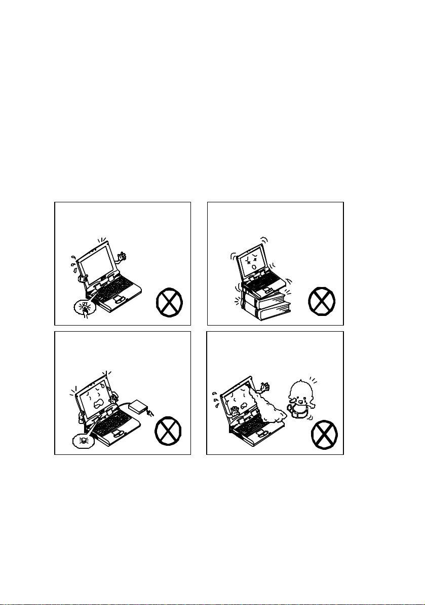
Safety Notice
Do not turn off power in
Do not turn off the peripheral
Do not place the computer on
Do not touch the poisonous liquid
The notebook computer is a delicate device that requires careful handling.
Negligence or mistaken use may cause serious damage. Before you learn to
operate or use this computer, you need to understand the instruction regarding
safety handling.
The following mentions the incorrect handling that is seriously inhibited. To
keep the computer from being damaged, please keep these precautions in your
mind.
operation.
device when the light is on.
unstable surface.
when the LCD is broken.
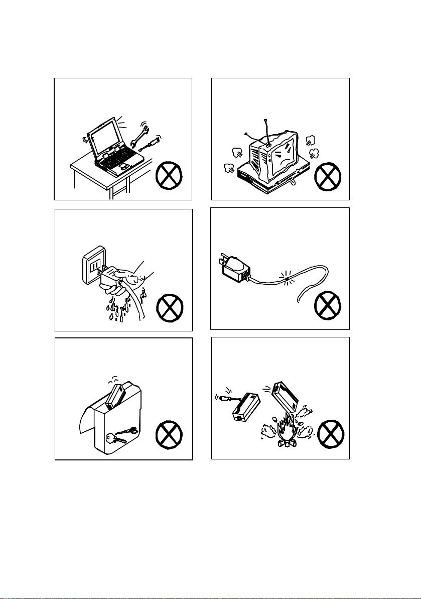
Do not disassemble the computer
Do not touch power cord by wet
Keep the computer away from any
Do not place anything heavy on the
Do not throw the computer or
yourself.
hand.
metal appliance.
computer.
Do not use broken power cord.
accessories into fire.
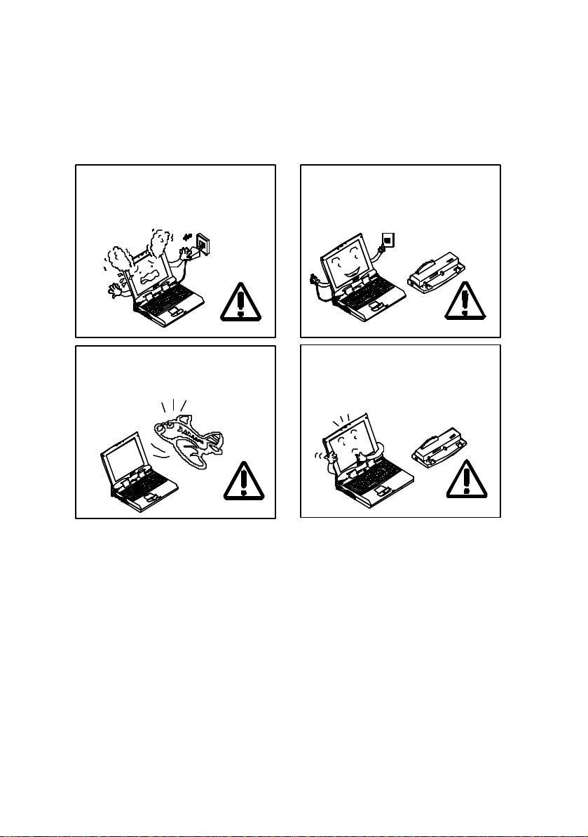
The following mentions the actions that are important for your computer. To
If there is unusual odor, heat or
Plug out the power cord in
Follow the use instruction in
Use the same brand of peripheral
keep your computer in the most excellent condition, please follow the
instruction as much as possible.
smoke, plug out the power cord
immediately.
taking airplane.
attaching peripheral devices.
devices.
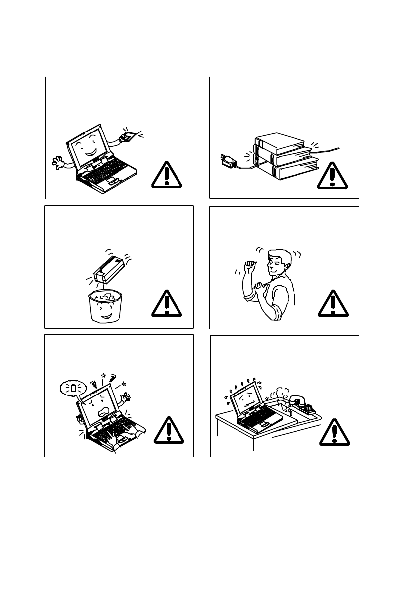
Do not place heavy thing on the
Affix tape to the contact plate while
Take a rest after a long term of
The data is easy to lose in low power
Please keep the computer away
Maintain your computer regularly.
power cord.
putting the battery into keeping box.
status.
work.
from humid environment.

Conventions
This manual uses the following conventions to describe, identify, and highlight
terms and operating procedures.
Text Conventions
Text in boldface contains messages that are important for safe operation. Please
read.
Characters in boldface represent specific items or keys, e.g. CardBus, Fn key.
File names are presented in bold capitals, e.g. A:\>0VMAK FIL /Pn.
Abbreviations
For the purpose of clarity, abbreviations are enclosed in parentheses following
their definition; for example, Enhanced Parallel Port (EPP) mode.
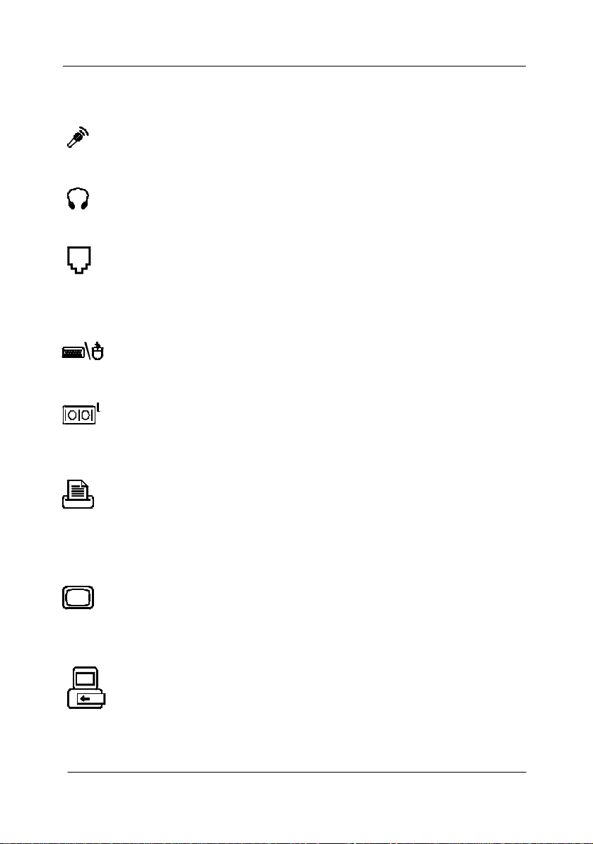
Icons
Icons identify ports and jacks of the Notebook computer. The system status
indicators are also identified with their relative icons.
Keys
Keys appear in boldface. A plus sign (+) between two keys indicates that they
should be pressed simultaneously.
Messages
Note: A note is an advice that helps you make best use of your
Notebook computer. Please read.
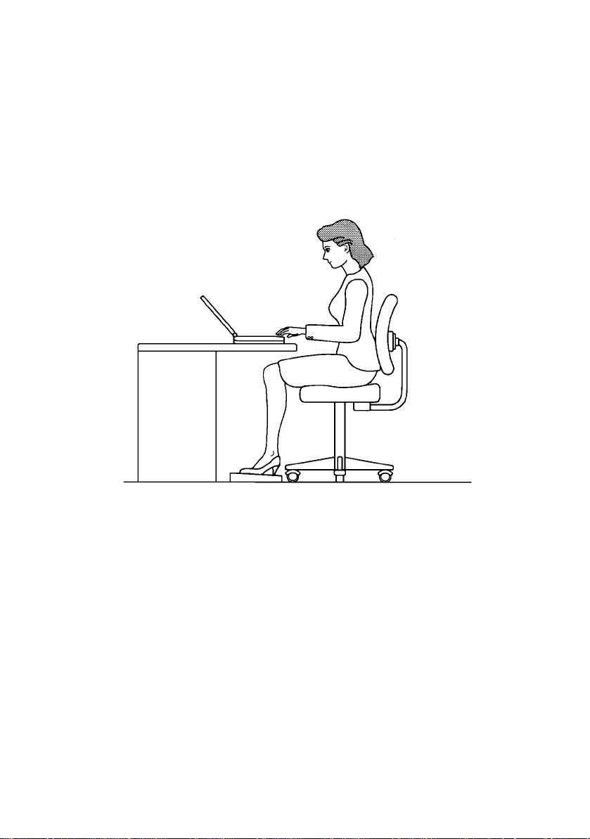
Ergonomics
Developing good work habits are important if you need to work in front of the
computer for long periods of time. Improper work habits can result in
discomfort or serious injury from repetitive strain to your hands, wrists or other
joints. The following are some tips to reduce the strain:
¦ Adjust the height of the chair and/or desk so that the keyboard is at or
slightly below the level of your elbow. Keep your forearms, wrists, and
hands in a relaxed position.
¦ Your knees should be slightly higher than your hips. Place your feet flat on
the floor or on a footrest if necessary.
¦ Use a chair with a back and adjust it to support your lower back
comfortably.
¦ Sit straight so that your knees, hips and elbows form approximately 90°
angles when you are working.

Lighting
Proper lighting and comfortable display viewing angle can reduce eye strain and
muscle fatigue in your neck and shoulders.
¦ Position the display to avoid glare or reflections from overhead lighting or
outsid e sources of light.
¦ Keep the display screen clean and set the brightness and contrast to levels
that allow you to see the screen clearly.
¦ Position the display directly in front of you at a comfortable viewing
distance.
¦ Adjust the display viewing angle to find the best position.
In addition, continuous concentration on computing work can result in
discomfort and injury. Remember to:
¦ Alter your posture frequently.
¦ Stretch and exercise your body several times a day.
¦ Take periodic breaks when you work at the computer for long periods of
time. Frequent and short breaks are of greater benefit than fewer and longer
breaks.

Table of Contents
Chapter 1: Getting Started
Unpacking---------------------------------------------------------------------------1-2
Operating Environment-----------------------------------------------------------1-3
Quick Start-up ----------------------------------------------------------------------1-4
Powering the System -----------------------------------------------------1-4
AC Power Adapter----------------------------------------------1-4
Battery Pack-------------------------------------------------------1-5
Inserting---------------------------------------------------1-5
Removing-------------------------------------------------1-5
Recharging by AC Power-----------------------------1-6
Proper Handling of the Battery Pack---------------1-6
Opening the LCD Cover -------------------------------------------------1-7
LED Indicators on the LCD Cover------------------------------------1-8
Top-Front View ---------------------------------------------------------------------1-9
LCD Panel -------------------------------------------------------------------1-9
Stereo Speakers -----------------------------------------------------------1-9
Trackpad and Buttons ---------------------------------------------------1-9
Keyboard -------------------------------------------------------------------1-9
Microphone----------------------------------------------------------------1-9
System Status LED Indicators-----------------------------------------1-10
Power Button --------------------------------------------------------------1-10
Rear View----------------------------------------------------------------------------1-12
Headphone Jack -----------------------------------------------------------1-12
Microphone-in Jack------------------------------------------------------1-12
Phone Jack ------------------------------------------------------------------1-12
PS/2 Type Port-------------------------------------------------------------1-12
Serial Port -------------------------------------------------------------------1-12
Parallel Port-----------------------------------------------------------------1-12
External Monitor (CRT) Port -------------------------------------------1-12
USB Port --------------------------------------------------------------------1-12
Right-side View ---------------------------------------------------------------------1-14
3.5” Floppy Diskette Drive ---------------------------------------------1-14
5.25” CD-ROM Drive-----------------------------------------------------1-14
PC Card Sockets-----------------------------------------------------------1-14
Infrared----------------------------------------------------------------------1-14
Right-side Stands---------------------------------------------------------1-14
Left-side View -----------------------------------------------------------------------1-16
DC-in Socket---------------------------------------------------------------1-16

Ventilation------------------------------------------------------------------1-16
Left-side Stands-----------------------------------------------------------1-16
Bottom View -------------------------------------------------------------------------1-17
2.5” Hard Disk Drive -----------------------------------------------------1-17
CPU Cover------------------------------------------------------------------1-17
Battery Pack----------------------------------------------------------------1-17
CD-ROM Cover-----------------------------------------------------------1-17
Chapter 2: Operation
Upgrading Processor Module --------------------------------------------------2-2
Replacing Processor Module ------------------------------------------2-3
Reinstalling Heat Sink -------------------------------------------------------2-5
Setting DIP Switch-----------------------------------------------------------------2-6
Accessing the 2-Pole DIP Switch-------------------------------------2-6
Ex panding Memory----------------------------------------------------------------2-7
Accessing the Memory Sockets --------------------------------------2-8
Installing Memory Module ------------------------------------2-9
Removing Memory Module -----------------------------------2-10
Using Hard Disk Drive------------------------------------------------------------2-11
Removing-------------------------------------------------------------------2-11
Inserting---------------------------------------------------------------------2-11
Replacing Hard Disk Drive ---------------------------------------------2-12
Using Floppy Disk Drive---------------------------------------------------------2-13
Inserting/Removing Diskettes-----------------------------------------2-13
Write-Protecting Diskettes ---------------------------------------------2-14
Do’s and Don’ts ----------------------------------------------------------2-14
Using CD-ROM --------------------------------------------------------------------2-15
Removing CD-ROM Module-------------------------------------------2-16
Loading Compact Discs-------------------------------------------------2-17
Handling of Compact Discs --------------------------------------------2-18
Using PC Card Sockets-----------------------------------------------------------2-19
Inserting PC Cards--------------------------------------------------------2-19
Removing PC Cards------------------------------------------------------2-20
Using Hot Keys--------------------------------------------------------------------2-21
Using Numeric Keypad-----------------------------------------------------------2-23
TV Out--------------------------------------------------------------------------------2-25
LCD Panel ----------------------------------------------------------------------------2-26
Using Power Management ------------------------------------------------------2-27
Advanced Power Management (APM 1.2)-------------------------2-27
Hard Disk Standby -------------------------------------------------------2-28

Global Standby------------------------------------------------------------2-28
Suspend and Resume----------------------------------------------------2-28
Powered On Suspend (POS) ----------------------------------2-29
Resume from POS Mode----------------------------2-29
Suspend To RAM (STR)---------------------------------------2-29
Resume from STR Mode---------------------------2-29
Suspend To Disk (STD)----------------------------------------2-30
Resume from STD Mode ---------------------------2-30
Attaching Peripheral Devices---------------------------------------------------2-31
Attaching a Phone Line-------------------------------------------------2-31
Attaching a PS/2 Keyboard or Mouse------------------------------2-32
Attaching a Serial Mouse -----------------------------------------------2-33
Attaching a Parallel Printer---------------------------------------------2-34
Attaching an External Monitor (CRT) -------------------------------2-35
Attaching a Proprietary Port Replicator-----------------------------2-36
Attaching a Video Input Device --------------------------------------2-37
Attaching a TV Set-------------------------------------------------------2-38
Attaching a USB-compatible Device---------------------------------2-39
Chapter 3: BIOS Utilities
Power On Self Test (POST)------------------------------------------------------3-2
POST Message: Normal Operation-----------------------------------3-2
POST Message: Error Detected---------------------------------------3-3
System Configuration Utility----------------------------------------------------3-4
Information in the System Configuration Utility------------------3-4
Initiating the System Configuration Utility-------------------------3-5
Initiating the System Configuration Utility-------------------------3-5
Working with the Menu Bar of the SCU--------------------3-6
Working with the Pull-down Menu of the SCU-----------3-7
Features of the System Configuration Utility----------------------3-8
Startup Menu-----------------------------------------------------3-8
Memory Menu----------------------------------------------------3-10
Disks Menu -------------------------------------------------------3-11
Components Menu----------------------------------------------3-12
Power Menu-------------------------------------------------------3-15
Exit Menu----------------------------------------------------------3-18

Chapter 4: Troubleshooting
Battery--------------------------------------------------------------------------------4-2
Power---------------------------------------------------------------------------------4-3
Hard Disk Drive --------------------------------------------------------------------4-3
Floppy Disk Drive -----------------------------------------------------------------4-4
Hardware Installation-------------------------------------------------------------4-4
LCD Panel ----------------------------------------------------------------------------4-5
Memory Module -------------------------------------------------------------------4-6
PC Card-------------------------------------------------------------------------------4-6
Boot Password ---------------------------------------------------------------------4-7
Audio ---------------------------------------------------------------------------------4-7
CD -------------------------------------------------------------------------------------4-8
Printer---------------------------------------------------------------------------------4-9
Chapter 5: Installing Drivers
Preparation --------------------------------------------------------------------------5-2
Installing Windows ---------------------------------------------------------------5-4
Drivers for Win95------------------------------------------------------------------5-5
Drivers for Win98------------------------------------------------------------------5-7
Drivers for WinNT 4.0------------------------------------------------------------5-8
Appendix A: Specifications --------------------------------------------------------------A-1
Appendix B: I/O Port Pin Assignments----------------------------------------------B-1

1-1
Chapter 1: Getting Started
This chapter provides a short introduction and tutorial that will familiarize you
with the Notebook system and get you up and running quickly. This Chapter
will discuss:
: Unpacking
: Operating Environment
: Quick Start-up
: Top-Front View
: Rear View
: Right-side View
: Left-side View
: Bottom View
Chapter 1: Getting Started
1-2
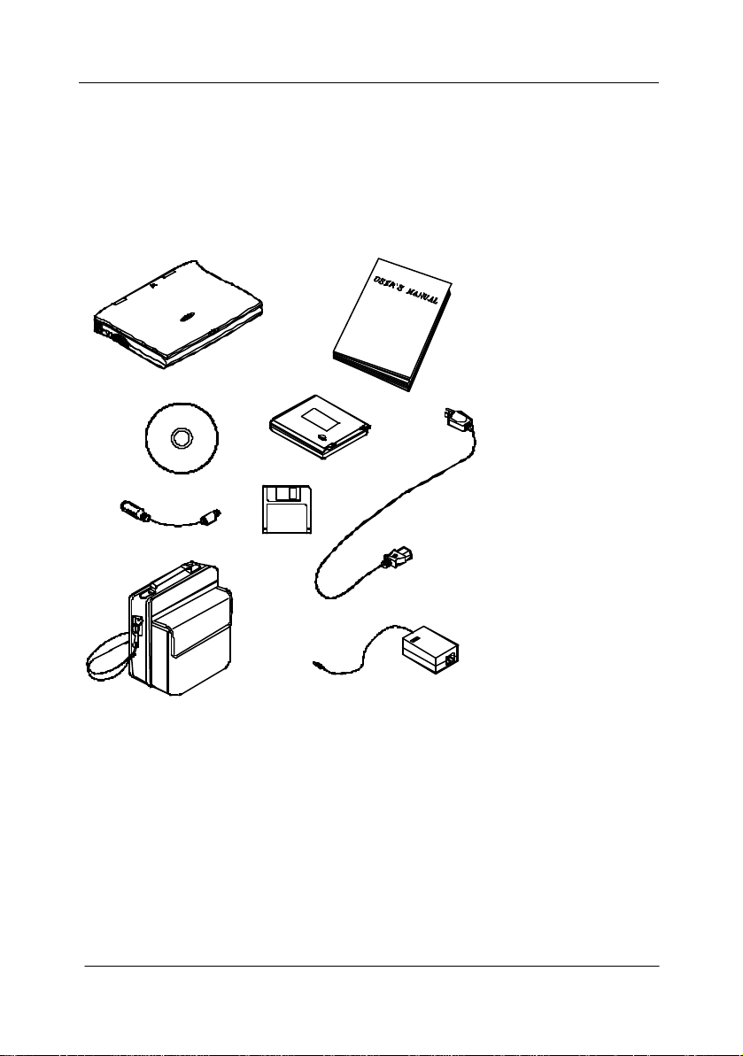
Unpacking
Carefully unpack the Notebook Computer and the included accessories (Figure
1-1). If there is any discrepancy or problem, contact your dealer immediately.
Be sure to save the packing materials in the event that the notebook needs to be
shipped at some point in the future.
m Notebook Computer.
m Carrying Bag.
m Power Adapter.
m Power Cord.
m User’s Manual.
m PS/2 Transfer
Cable.
m Battery Pack.
m Utilities Diskettes.
m CD for drivers.
Figure 1-1
User’s Manual
1-3
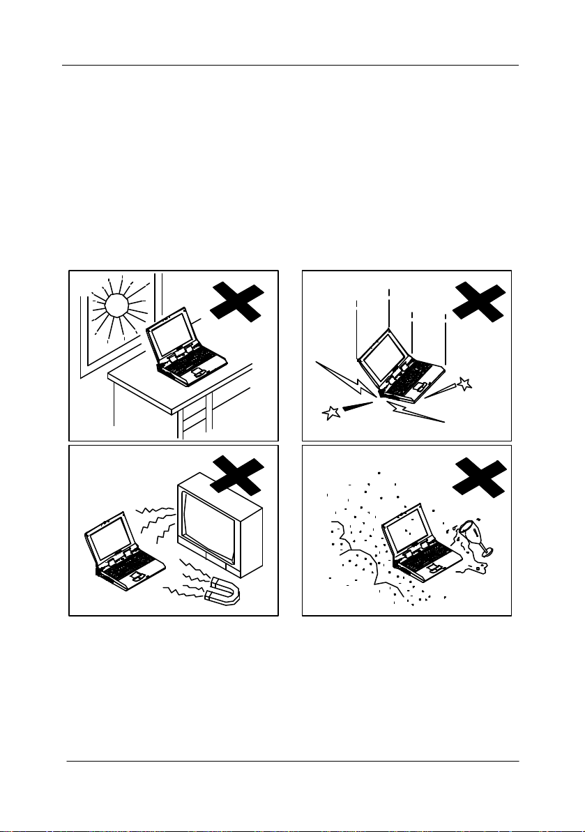
Operating Environment
As with any other precision electronic equipment, proper care and operation of
your Notebook will provide long and reliable service. Be sure the computer
system is not:
m Exposed to excessively heat or directly sunlight.
m Subjected to shock or vibration.
m Exposed to strong magnetic fields.
m Left in a place where foreign matter or moisture may enter the system.
Figure 1-2
Chapter 1: Getting Started
1-4
Quick Start-up
Powering the System
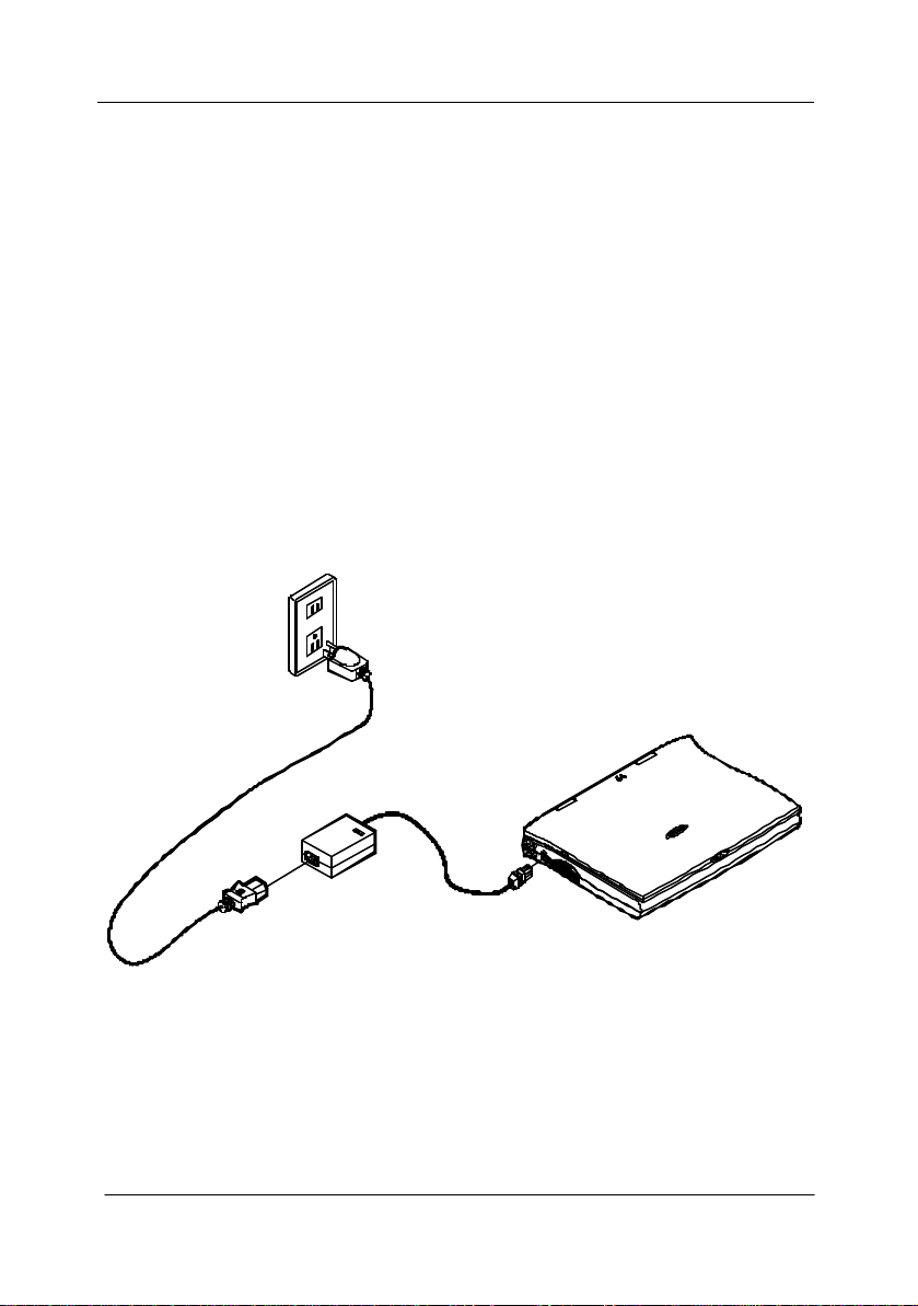
AC Power Adapter
Use only the power adapter that comes with your Notebook Computer. System
operation with an incorrect power adapter will cause damage to the Notebook
and its components.
1. Plug the power adapter to the DC-in socket on the left panel of the
Notebook.
2. Connect the power cord to the power adapter.
3. Plug the AC power cord into a properly grounded outlet (Figure 1-3).
4. Refer to Chapter 1, System Status LED Indicators for more information on
system power status.
User’s Manual
Figure 1-3
1-5
Battery Pack
Power for continuous portable operation of the Notebook is provided by a
battery pack. When using the battery no external power source is required.
However, the actual operating time will be determined by the application used
and the configuration set.
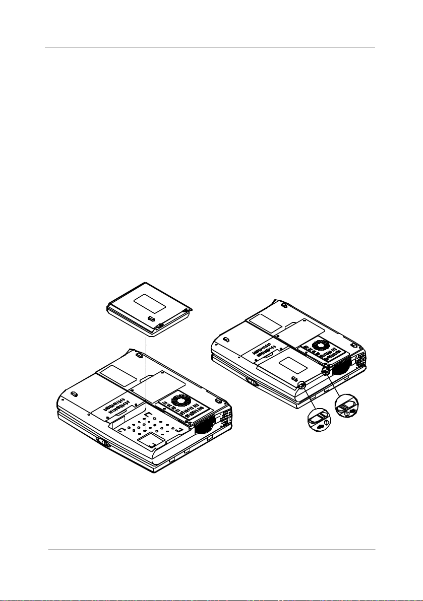
Inserting
1. Turn the Notebook over.
2. Position the battery pack and firmly fit it into the Notebook (Figure 1-4).
3. The two latches will click into place when it is seated.
Removing
4. Turn the Notebook over.
5. Press the two latches in the direction indicated to release the battery pack.
(Figure 1-5)
6. Carefully lift the battery pack from the Notebook.
Figure 1-4 Figure 1-5
Chapter 1: Getting Started

1-6
Recharging by AC Power
The system’s battery pack will recharge whenever the system is plugged into the
AC power supply, regardless of whether the system is being operated or not.
Please refer to Chapter 1, System Status LED Indicators for more information
concerning battery charge status.
Off-Line Charge The Notebook system is powe red off. Connect
the AC adapter to the unit. Its DC output will be
used solely to charge the battery. It will take
hours to bring a completely discharged battery to
its full charge state.
Trickle Charge The Notebook system is powered on. Again,
make sure the AC adapter is connected to the
unit. Its DC output will both power the system
and charge the battery. It may take more hours
than off-line charge to charge the battery.
Proper Handling of the Battery Pack
• Do not attempt to disassemble the battery under any circumstances.
• The battery may explode if exposed to fire or high temperatures.
• Avoid short circuiting the battery by preventing contact between the metal
terminals (+, −).
User’s Manual
1-7
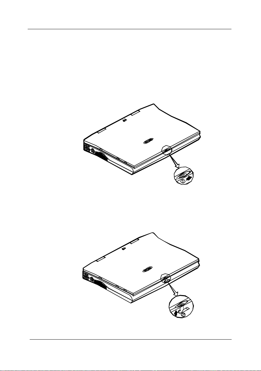
Opening the LCD Cover
1. To release the top cover slide the latch to the right (Figure 1-6).
2. Lift the top cover to reveal the LCD panel and keyboard (Figure 1-7).
3. Adjust the LCD panel to a comfortable viewing angle.
4. Press the power button to turn the system on or off (refer to Chapter 1,
Top-Front View for the information of the power button).
Figure 1-6
Figure 1-7
Chapter 1: Getting Started
1-8
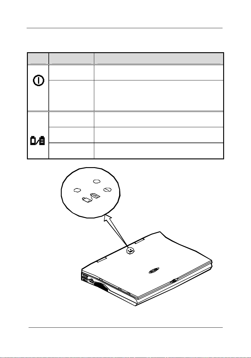
LED Indicators on the LCD Cover
Icon Color Description
Green Battery power is used with system turned on.
Red AC power is used with system turned on or
AC and Battery are used with system turned on.
Green Battery is fully charged.
Red Battery is being charged.
Blinking Red Battery power is critically low.
User’s Manual
Figure 1-8

1-9
Top-Front View
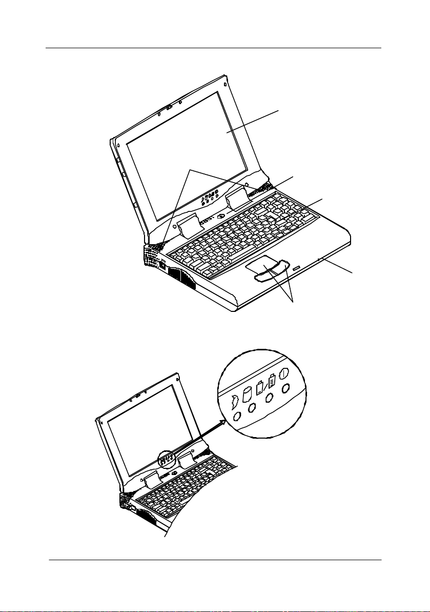
LCD Panel
The Notebook provides you with a large LCD panel. Depending upon
the model you have purchased, it can either be a 14.1”/13.3” XGA
(1024x768 pixels) compatible, using TFT technology, or a 12.1” SVGA
(800x600 pixels) compatible, using DSTN technology. The LCD panel is
driven by a AGP local bus video controller with 4MB video memory.
Stereo Speakers
Two built-in speakers provide clear stereo sound.
Trackpad and Buttons
The pointing device features a sensitive glide pad for precise movements.
It functions like a two -button mouse does. The right trackpad button is
equivalent to the right mouse button; the left trackpad button is
equivalent to the left mouse button.
Keyboard
The Notebook utilizes a Windows 95 keyboard that is integrated with the
numeric keypad. It is detachable for various language versions. You
may refer to Chapter 2: Operation for more information.
Microphone
This is the built-in microphone for recording sound into your
applications.
Chapter 1: Getting Started
1-10
System Status LED Indicators
The LED indicators display the system’s operation status.
Icon Color Description
Green Battery power is used with system turned on.
Red AC power is used with system turned on or
AC and Battery are used with system turn on.
Green Battery is fully charged.
Red Battery is being charged.
Blinking Red Battery power is critically low.
Green The hard disk is being accessed.
Green
The system has entered Suspend -To-RAM (STR) or
Power-On-Suspend (POS) mode.
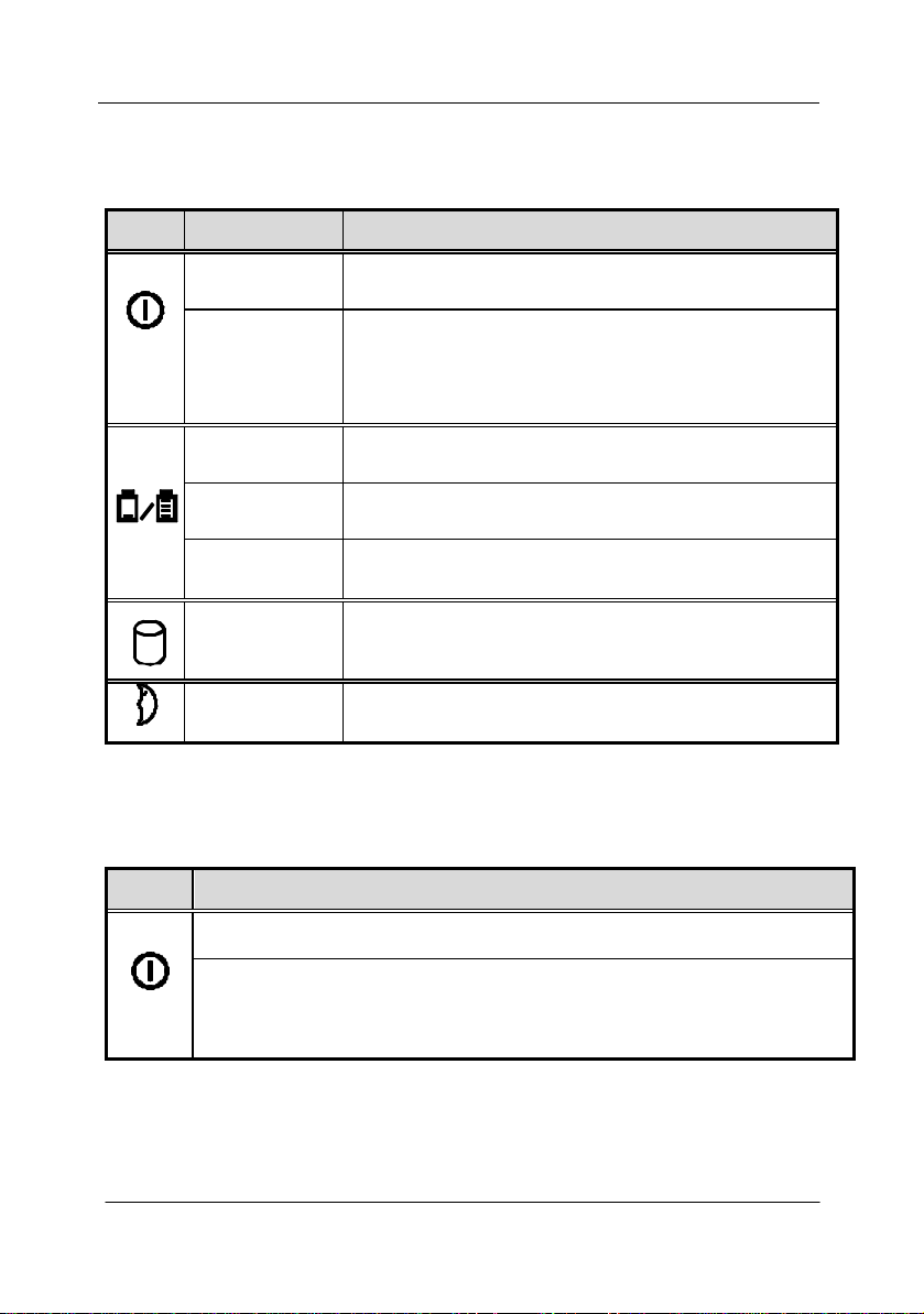
Power Button
Icon Description
Use this button to turn the system on or off.
Note: After turning off the system, wait for a few seconds to power it on
again when you need to.
User’s Manual
After proper configuration under SCU, this button can be used as
suspend/resume hot button (refer to Chapter 3: BIOS Utilities, Power
Menu for more information).
1-11
LCD Panel
Stereo Speakers
Power Button
Keyboard
Microphone
Figure 1-9
Figure 1-10
Chapter 1: Getting Started
Trackpad & Buttons
1-12
Microphone-in Jack
Headphone can be attached to the system through this jack for audio output,
in modem. To use the function,
o the jack and insert a modem card (Optional) into the
A PS/2 type mouse and keyboard may be connected to the system using this
This parallel port supports EPP (Enhanced Parallel Port) and ECP (Extended
ransmission of the display to an external monitor.
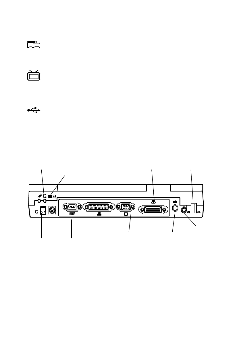
Rear View
Use this jack to connect a microphone to the system for audio input.
Headphone Jack
so can external speakers that have built-in output power amplifier.
Phone Jack
The phone jack is used to support the built attach a phone line t
modem socket on the mainboard. See figures (2-21.1 / 2-21.2).
PS/2 Type Port
port.
Serial Port
This port is NS 16C550 compatible. It features a 9-pin connector for the
addition of an external mouse for example.
Parallel Port
Capabilities Port) modes.
External Monitor (CRT) Port
This port is used for t
Simultaneous display with the LCD panel is available.
Expansion Port
This port is used to connect the proprietary Port Replicator.
User’s Manual
1-13
RCA Jack
elect
Chapter
The Universal Serial Bus (USB) port simplifies the expansion capability
equipped
This jack accepts analog composite signals from external video devices,
e.g. camera, CCD.
S-video Jack
Use this jack to transmit video signal to a TV set. You may need to s
the video standard (NTSC/PAL) for video display (please refer to
3, Components Menu for more information).
USB Port
for peripherals by daisy-chain connection of a number of USBdevices.
Microphone-in jack
Headphone jack
Expansion port
USB port
PS/2 type port
Phone Jack
Chapter 1: Getting Started
Serial port
Parallel port
Figure 1-11
CRT port
RCA Jack
S-Video Jack

1-14
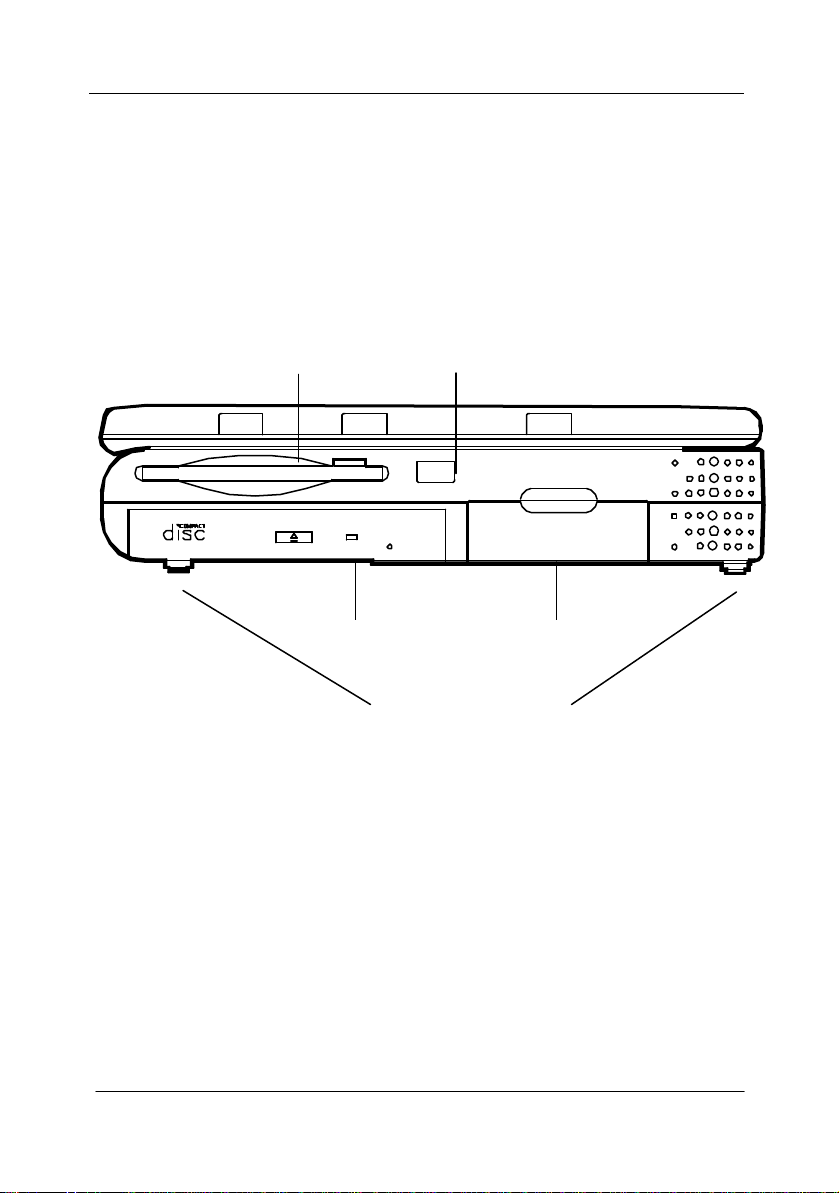
3.5” Floppy Diskette Drive
loppy drive installed. Press
ROM module is designed to be changeable installing or
ROM drive. The eject button is
ROM drive. Pressing it
for more
One Type III or two Type II PC cards may be used. Both sockets will
pabilities when a PC card is inserted. To eject the PC
The system adopts infrared technology as the interface for simple, fast and
compatible
device. It implements IrDA (HPSIR), Amplitude Shifted Keyed IR
(ASKIR), and Fast IR (FIR). No object should be blocking the line of sight
equipped device. For further
e wireless device you wish to connect
When a high speed CPU is installed, the erecting stands on both sides will
Right-side View
The Notebook comes standard with a 1.44MB f
the button on its top-right side to eject the diskette.
5.25” CD-ROM Drive
The 5.25” IDE CDremoving the two screws that fasten the CDlocated in the middle of the front cover of the CDwill release the CD tray. Refer to Chapter 2: Operation,
information.
PC Card Sockets
expand the system ca
card, press the appropriate eject button (Figure 2-17).
Infrared
convenient data exchange from the Notebook to an infrared-
between the Notebook and the infraredinformation refer to the manual of th
on how to use the point-and-shoot operation.
Right-side Stands
help heat dissipation during operation.
User’s Manual
1-15
3.5” Floppy Disk Drive
Infrared
5.25” CD-ROM
PC Card Sockets
Right-side Stands
Figure 1-12
Chapter 1: Getting Started
 Loading...