

Euro CLS IA31 User Manual
IA31 Motherboard
Ultra slim SBC w/ Intel®ATOM N270
1.6GHz Processor, VGA, LCD, Giga
Ethernet, and Mini-PCI interface.
USER MANUAL Version 1.0
ZI de St Génault 16 rue Jean Mermoz 91080 Courcouronnes France Tél : +33 (0) 1 60 78 97 93 Fax : +33 (0) 1 60 79 14 88 Web : www.eurocls.com

IA31 Motherboard User Manual
II
FCC Statement
This device complies with part 15 FCC rules. Operation is subject to
the following two conditions:
This device may not cause harmful interference.
This device must accept any interference received including
interference that may cause undesired operation.
This equipment has been tested and found to comply with the limits for a class "a"
digital device, pursuant to part 15 of the FCC rules. These limits are designed to
provide reasonable protection against harmful interference when the equipment is
operated in a commercial environment. This equipment generates, uses, and can
radiate radio frequency energy and, if not installed and used in accordance with the
instruction manual, may cause harmful interference to radio communications.
Operation of this equipment in a residential area is likely to cause harmful
interference in which case the user will be required to correct the interference at him
own expense.

IA31 Motherboard User Manual
III
Copyright Notice
ALL RIGHTS RESERVED. No part of this document may be reproduced, copied,
translated, or transmitted in any form or by any means, electronic or mechanical, for
any purpose, without the prior written permission of the original manufacturer.
Trademark Acknowledgement
Brand and product names are trademarks or registered trademarks of their respective
owners.
Disclaimer
We reserve the right to make changes, without notice, to any product, including
circuits and/or software described or contained in this manual in order to improve
design and/or performance. We assume no responsibility or liability for the use of the
described product(s), conveys no license or title under any patent, copyright, or masks
work rights to these products, and makes no representations or warranties that these
products are free from patent, copyright, or mask work right infringement, unless
otherwise specified. Applications that are described in this manual are for illustration
purposes only. We make no representation or warranty that such application will be
suitable for the specified use without further testing or modification.
Warranty
We warrant that each of its products will be free from material and workmanship
defects for a period of one year from the invoice date. If the customer discovers a
defect, We will, at its option, repair or replace the defective product at no charge to
the customer, provided it is returned during the warranty period of one year, with
transportation charges prepaid. The returned product must be properly packaged in its
original packaging to obtain warranty service.
If the serial number and the product shipping data differ by over 30 days, the
in-warranty service will be made according to the shipping date. In the serial numbers
the third and fourth two digits give the year of manufacture, and the fifth digit means
the month (e. g., with A for October, B for November and C for December).
For example, the serial number 1W07Axxxxxxxx means October of year 2007.

IA31 Motherboard User Manual
IV
Packing List
Before using this Motherboard, please make sure that all the items listed below are
present in your package:
IA31 Motherboard
IA31 SBC User Manual
HDD IDE Cable
User’s Manual & Driver CD
If any of these items are missing or damaged, contact your distributor or sales
representative immediately.
Customer Service
We provide service guide for any problem as follow steps:First, visit the website at to
find the update information about the product. Second, contact with your distributor,
sales representative, or our customer service center for technical support if you need
additional assistance. You may have the following information ready before you call:
Product serial number
Peripheral attachments
Software (OS, version, application software, etc.)
Description of complete problem
The exact wording of any error messages
In addition, free technical support is available from our engineers every business day.
We are always ready to give advice on application requirements or specific
information on the installation and operation of any of our products. Please do not
hesitate to call or e-mail us.

IA31 Motherboard User Manual
V
Safety Precautions
Warning!
Always completely disconnect the power cord from your chassis
whenever you work with the hardware. Do not make connections
while the power is on. Sensitive electronic components can be
damaged by sudden power surges. Only experienced electronic
personnel should open the PC chassis.
Caution!
Always ground yourself to remove any static charge before
touching the CPU card. Modern electronic devices are very
sensitive to static electric charges. As a safety precaution, use a
grounding wrist strap at all times. Place all electronic components
in a static-dissipative surface or static-shielded bag when they are
not in the chassis.
7

IA31 Motherboard User Manual
VI
Safety and Warranty
1. Please read these safety instructions carefully.
2. Please keep this user's manual for later reference.
3. Please disconnect this equipment from any AC outlet before cleaning. Do not use
liquid or spray detergents for cleaning. Use a damp cloth.
4. For pluggable equipment, the power outlet must be installed near the equipment
and must be easily accessible.
5. Keep this equipment away from humidity.
6. Put this equipment on a reliable surface during installation. Dropping it or letting
it fall could cause damage.
7. The openings on the enclosure are for air convection. Protect the equipment from
overheating. DO NOT COVER THE OPENINGS.
8. Make sure the voltage of the power source is correct before connecting the
equipment to the power outlet.
9. Position the power cord so that people cannot step on it. Do not place anything
over the power cord.
10. All cautions and warnings on the equipment should be noted.
11. If the equipment is not used for a long time, disconnect it from the power source
to avoid damage by transient over-voltage.
12. Never pour any liquid into an opening. This could cause fire or electrical shock.
13. Never open the equipment. For safety reasons, only qualified service personnel
should open the equipment.
14. If any of the following situations arises, get the equipment checked by service
personnel:
A. The power cord or plug is damaged.
B. Liquid has penetrated into the equipment.
C. The equipment has been exposed to moisture.
D. The equipment does not work well, or you cannot get it to work according to
the user’s manual.
E. The equipment has been dropped and damaged.
F. The equipment has obvious signs of breakage.
15. Do not leave this equipment in an uncontrolled environment where the storage
temperature is below -20° C (-4°F) or above 60° C (140° F). It may damage the
equipment.

IA31 Motherboard User Manual
VII
Revision History
Version Date Note Author
1.0 2009.03.25 Initial Draft Aladin Huang

IA31 Motherboard User Manual
VIII
Contents
CHAPTER 1 GENERAL INFORMATION.......................................1
1.1 I
NTRODUCTION
...............................................................................1
1.2 F
EATURE
.........................................................................................1
1.3 M
OTHERBOARD SPECIFICATIONS
....................................................2
1.4 F
UNCTION BLOCK
...........................................................................3
1.5 B
OARD DIMENSIONS
........................................................................4
CHAPTER 2 INSTALLATIONS.........................................................6
2.1 M
EMORY MODULE
(DIMM)I
NSTALLATION
................................6
2.2 I/O E
QUIPMENT INSTALLATION
.......................................................7
2.3 J
UMPERS AND CONNECTORS
...........................................................8
2.4 J
UMPER SETTING
.............................................................................9
2.5 C
ONNECTORS AND PIN ASSIGNMENT
............................................ 11
CHAPTER 3 GRAPHIC DRIVER INSTALLATION 錯誤! 尚未定
義書籤。
3.1
STANDARD
CMOS F
EATURE
......................錯誤
錯誤錯誤
錯誤! 尚未定義書籤
尚未定義書籤尚未定義書籤
尚未定義書籤。。。。
3.2
PANEL RESOLUTION SETTING
.....................錯誤
錯誤錯誤
錯誤! 尚未定義書籤
尚未定義書籤尚未定義書籤
尚未定義書籤。。。。
CHAPTER 4 CHIPSET DRIVER INSTALLATION .....................28
4.1
STANDARD
CMOS F
EATURES
........................................................28
CHAPTER 5 ETHERNET DRIVER INSTALLATION..................33
5.1
INTRODUCTION
..............................................................................33
5.1 I
NSTALLATION OF ETHERNET DRIVER
...........................................34
CHAPTER 6 AUDIO DRIVER INSTALLATION..........................38
6.1
INTRODUCTION
..............................................................................38
6.2 I
NSTALLATION OF AUDIO DRIVER
.................................................38
CHAPTER 7 AMI BIOS SETUP ......................................................41
7.1 S
TARTING SETUP
...........................................................................41
7.2 S
YSTEM OVERVIEW
.......................................................................42
7.3
ADVANCED SETTING
....................................................................43
NOTE1: DIGITAL I/O SAMPLE CODE.............................................75

IA31 Motherboard User Manual
1
General Information
This chapter includes IA31 Motherboard background
information.
Sections include:
Introduction
Feature
Motherboard Specification
Function Block
Board Dimensions
C H A P T E R
1

IA31 Motherboard User Manual
1
Chapter 1 General Information
1.1 Introduction
IA31 SBC integrates Intel 945GSE North Bridge and Intel ICH7M South Bridge
which are designed for use with Intel’s mobile platform. Intel’s 945GSE platform
delivers the performance and high scalability cutting-edge embedded computing
application.
In peripheral connectivity, IA31 SBC with Mini-PCI I/O ports, Giga LAN, two
SATA connectors, and four Hi-Speed USB connectors.
Thus, IA31 SBC is designed to satisfy most of the applications in the industrial
computer market, such as Gaming, POS, KIOSK, Industrial Automation, and
Programmable Control System. It is a compact design to meet the demanding
performance requirements of today’s business and industrial applications.
1.2 Feature
Supports Intel® Atom N270 1.6GHz processors
System memory up to 2GB DDR2 400/533, 1x SO-DIMM
Integrated Intel 945GSE + ICH7M Chipset
Intel® GMA950 graphic engine Integrated 224MB shared supports VGA
Gigabit Ethernet
1 x Mini PCI, 4 x COM, 4 x USB2.0, 1 x CF
2 x SATA,
4DI/ 4DO
IA31 Motherboard User Manual
2
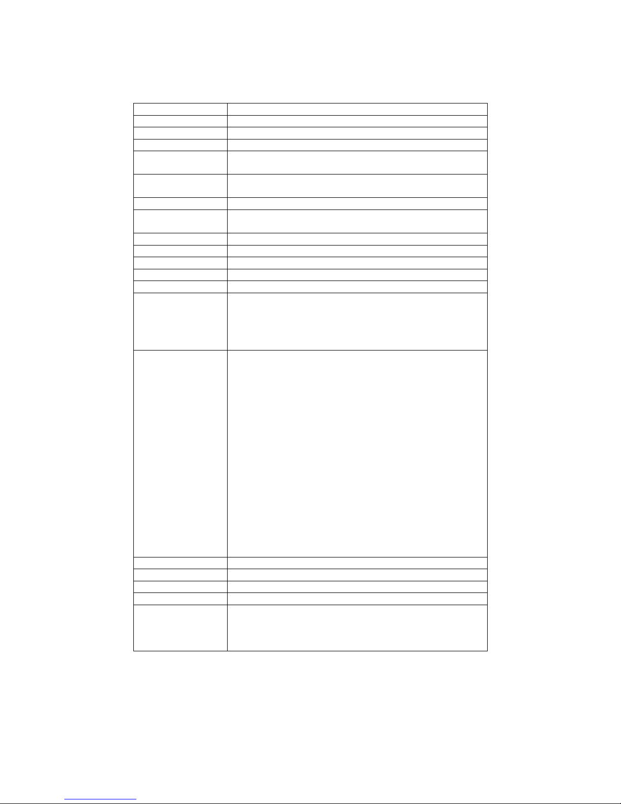
1.3 Motherboard Specifications
CPU Type Intel® Atom N270 1.6GHz Processor
CPU FSB 533 MHz
Chipset Intel 945GSE / ICH7M
BIOS AMI 4Mbit Flash
VGA
Intel® GMA950 Graphic engine
224MB shared with system memory
LVDS
Intel® 82945GSE built in single- or Dual-channel panel
support up to 1600 x 1200, 24bit
LAN 1 x Giga LAN ( Realtek RTL8111B Controller )
Memory Type
1 x DDR2 DIMM socket, supports up to 2GB DDR2
400/533 SDRAM
LPC I/O Winbond W83627EHG
Keyboard/Mouse 1 x PS/2 Keyboard/Mouse connectors
IDE Interface Dual channels; supports Ultra DMA 33/66/100
Sound Realtek ALC655 (Line-in, Line-out, Mic in)
USB 4 ports, USB 2.0 (2 x USB Connector, 2 x USB pin-header )
Edge Connectors
1 x +12V DC-IN Jack
1 x PS/2 connector for keyboard/mouse
1 x DB9 for COM3
1 x VGA out connector
1 x Gigabit LAN RJ-45 + 1 x dual USB stack connector
On Board
Pin-Header
Connectors
1 x 44 pins box-header
2 x SATA connector for SATAI/II 3.0 Gb/s
1 x 13pins pin-header for Front Panel2
1 x 10pins pin-header for Front Panel1(2x5)
1 x 3pins pin-header for CPU Fan
1 x 3pins pin-header for System FAN
1 x 8pins pin-header for 5V/12V external power
1 x 2pins pin-header for 5V external power
1 x 2pins pin-header for 12V external power
1 x 4pins ATX 12V connector
2 x 2pins pin-header for Front Audio (with Amp.)
1 x 8pins pin-header for USB 3/4(2x4)
1 x 10pins pin-header for COM3(RS232)(2x5)
1 x 20pins pin-header for COM1/2(RS232)(2x10)
1 x 40pins DF13 Connector for LVDS
1 x 3pins digital panel backlight brightness controller
1 x 7pins digital panel backlight controller
1 x 10pins pin-header for DIO(2x5)
Power Connector Input: 4-pin ATX 12V Power input
Expansion Slots 1 x Mini-PCI
Form Factor Ultra Slim Board
Dimensions 146mm x 126.6mm
Mechanical &
environmental
Operating temperature: 0 deg. C to 60 deg. C
Operating Humidity: 30 ~ 90% Relative humidity,
non-condensing
Certification: CE, FCC, RoHS
IA31 Motherboard User Manual
3
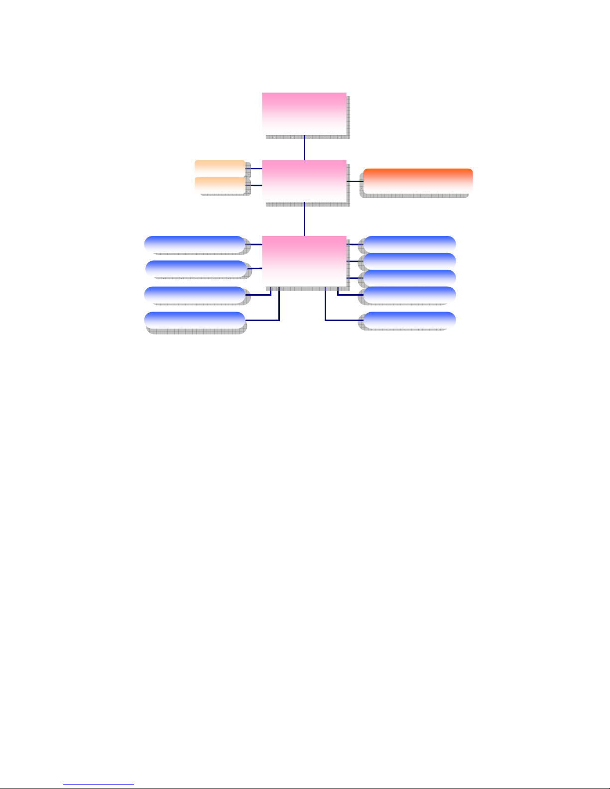
1.4 Function Block
Atom N270 1.6GHz
Intel 945GSE
ATOM N270
1.6GHz
Processor
FSB 400
66MHz Hub Interface 1.5
CRT
LVDS
1600*1200
24bit/Dual CH
SO-DIMM x 1
DDR2 533/400 Max.
2GB
1 x IDE Host
ATA100
Mini PCI
33MHz
LAN
USB
1GB/s
480MB/s
Audio
Super IO
Secondary IO
WW8833226677EEHHGG
FFiinntteekk 8811221166DD
SPI ROM
RRTTLL AALLCC665555
Intel ICH7M
3GB/s
SATA II 1, SATAII 2
IA31 Motherboard User Manual
4
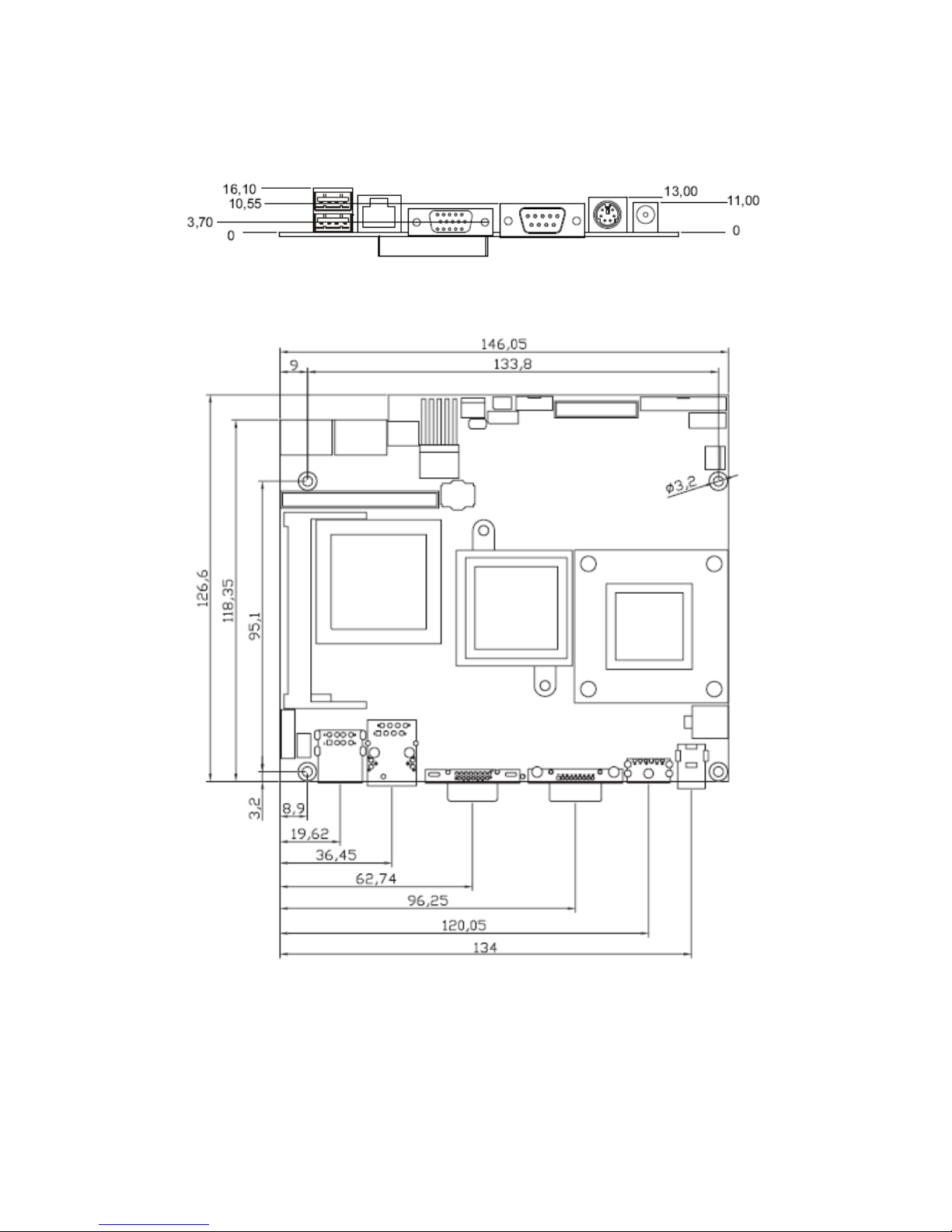
1.5 Board dimensions

IA31 Motherboard User Manual
5
Installations
This chapter provides information on how to use the
jumps and connectors on IA31 Motherboard.
The Sections include:
Memory Module Installation
I / O Equipment Installation
Setting the Jumpers
Connectors on IA31 Motherboard
C H A P T E R
2
IA31 Motherboard User Manual
6
Chapter 2 Installations
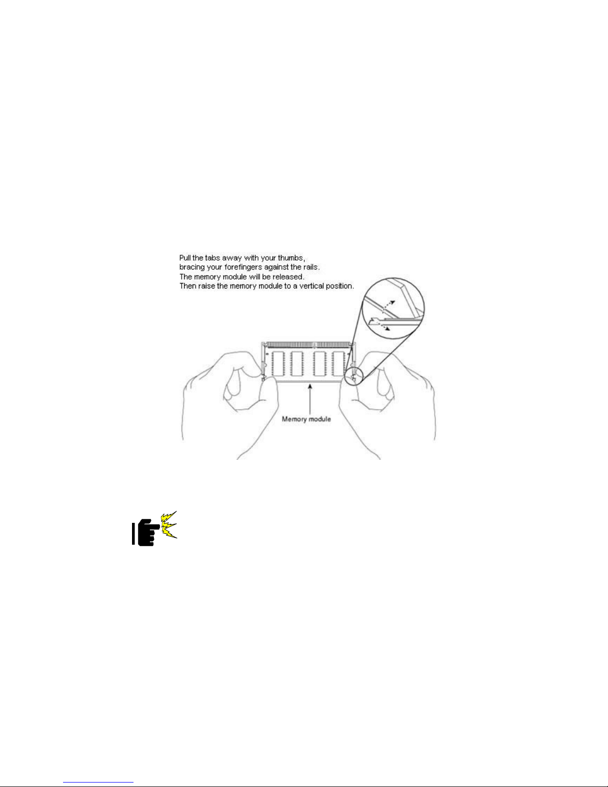
2.1 Memory Module((((DIMM))))Installation
IA31 motherboard supports one 200-pin SODIMM slot. The socket supports up to
2GB DDR2 400/533 SDRAM.
Step.2. Press downwards on SODIMM until the retaining clips at both ends fully snap
back in place and the SODIMM is properly seated.
Caution
!
The SODIMM only fits in one correct orientation. It will cause
permanent damage to the development board and the SODIMM if
the SODIMM is forced into the slot at the incorrect orientation.

IA31 Motherboard User Manual
7
2.2 I/O Equipment Installation
2.2.1 12V DC-IN
The Motherboard allows plugging 12V DC-IN jack on the board without another
power module converter under powered consumption by Intel Atom N270 1.6GHz
processor.
2.2.2 PS/2 Keyboard and PS/2 Mouse
The Motherboard provides one PS/2 interface. The PS/2 connector supports Keyboard
and Mouse.
2.2.3 Serial COM ports
Four RS-232 connectors build in the rear I/O. Fourth optional COM ports support
RS-232. When an optional touch-screen is ordered with PPC, serial com port can
connect to a serial or an optional touch-screen. One optional COM port supports
RS232/422/485 choice through jumper setting.
2.2.4 External VGA
The Motherboard has one VGA port that can be connected to an external CRT/ LCD
monitor. Use VGA cable to connect to an external CRT / LCD monitor, and connect
the power cable to the outlet. The VGA connector is a standard 15-pin D-SUB
connector.
2.2.5 Ethernet interface
The Motherboard is equipped with Realtek RTL8111B chipsets which is fully
compliant with the 10/100/1000 Mbps Ethernet protocol compatible. It is supported
by major network operating systems. The Ethernet ports provide two standard RJ-45
jacks.
2.2.6 USB ports
Four USB devices (Two with pin headers) may be connected to the system though an
adapter cable. Various adapters may come with USB ports. USB usually connect the
external system to the system. The USB ports support hot plug-in connection.
Whatever, you should install the device driver before you use the device.
2.2.7 Audio Jack ( Pin-header)
The Audio 5.1 channel capabilities are provided by a Realtek ALC655 chipset
supporting digital audio outputs. The audio interface includes Mic-in,: line-in and
line-out.

IA31 Motherboard User Manual
8
2.3 Jumpers and Connectors
TOP
Panel 1
CPU Fan1
ATX12V1
CON1
CON20
CON3
CON10
CON11
IDE1
USB1
CON19
SATA2 SATA1
CON18
CON17 CON16
NB Fan1
JP6
CON14
CON6
CON12 Panel 2
JP7
IA31 Motherboard User Manual
9
2.4 Jumper Setting
A pair of needle-nose pliers may be helpful when working with jumpers. If you have
any doubts about the best hardware configuration for your application, contact your
local distributor or sales representative before you make any changes. Generally, you
simply need a standard cable to make most connections.
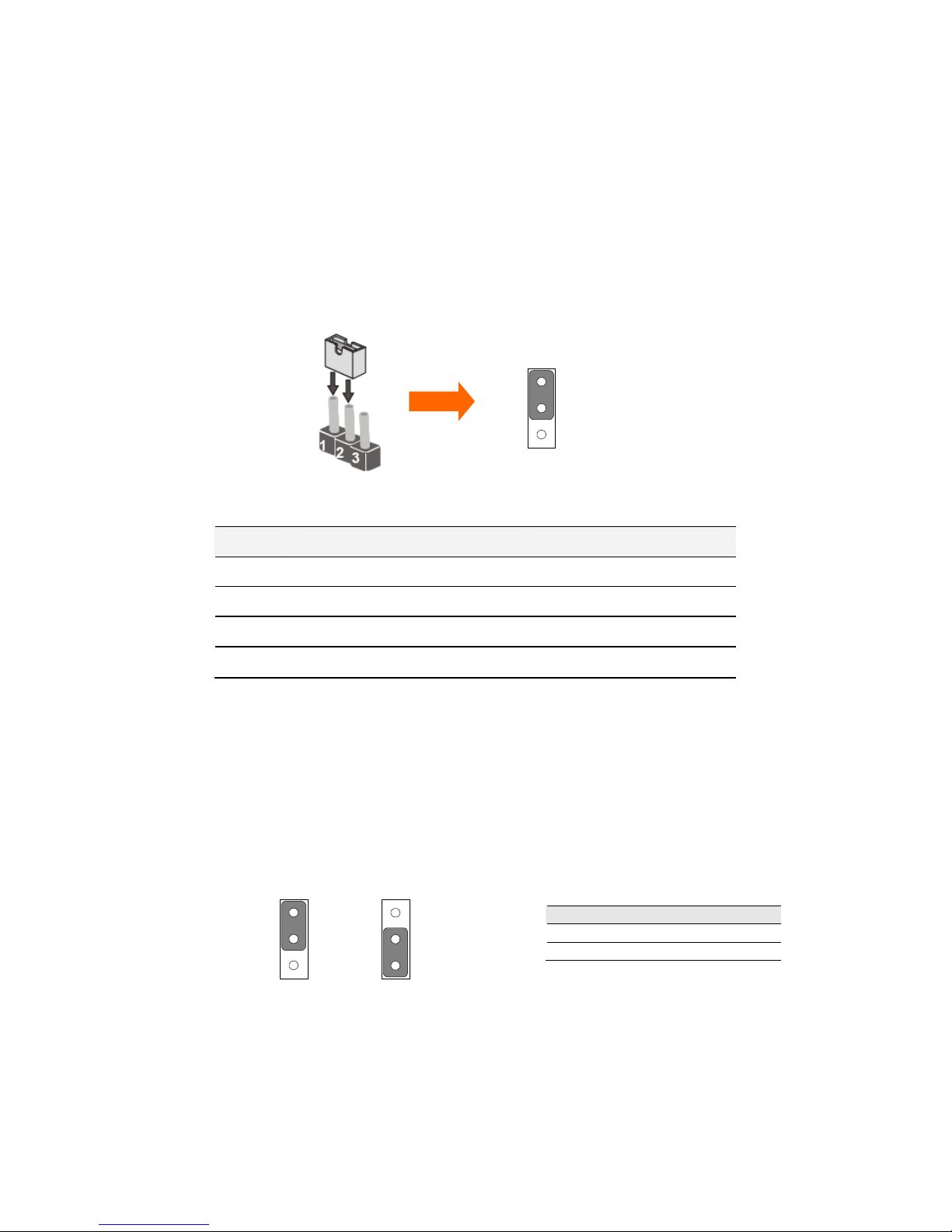
The jumper setting diagram is as below. If a jumper shorts pin 1 and pin 2, the setting
diagram is shown as the right one.
The following tables list the function of each of the board's jumpers.
Label Function Note
JP1 Clear CMOS 3x1 header , pitch 2.0mm
JP2 CF CARD PRIORITY 3x1 header , pitch 2.0mm
JP6 RS232 / RS422 / RS485 Selector
2x3 header , pitch 2.0mm
JP7 LVDS VOLTAGE 2x3 header , pitch 2.0mm
2.4.1 JP1: Clear CMOS
User must make sure the power supply to turn off the power supply before setting
Clear CMOS. Users remember to setting jumper back to Normal before turning on the
power supply. Default: 2 short 3.
Pin No. Functions
1 Short 2 Clear CMOS
2 Short 3 Normal
1
2
3
Clear CMOS
1
2
3
Normal
1
2
3
IA31 Motherboard User Manual
10
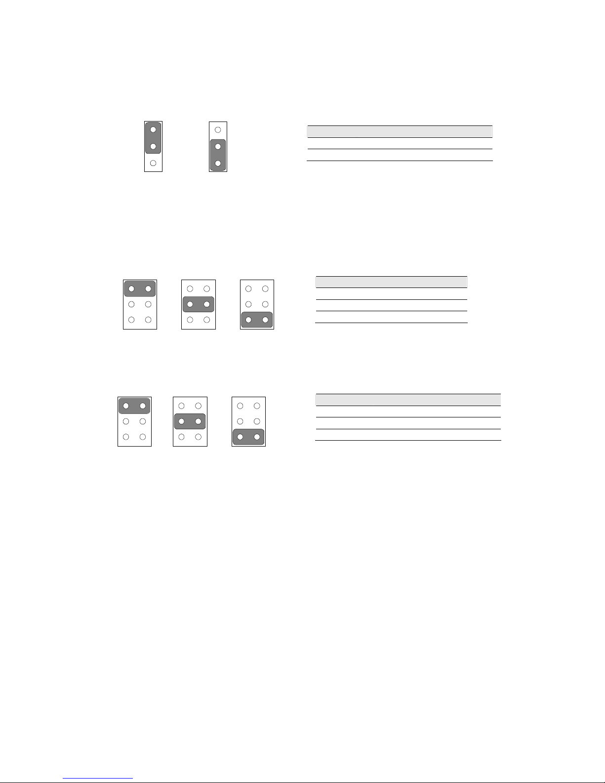
2.4.2 JP2 : CF Card Priority
JP901 can be configured to operate CF Card Priority in Master/Slave mode.
2.4.3 JP6: RS232 / RS422 / RS485 Selector
The jumper can be configured to operate COM2 in RS-232/422/485 mode. And the
setting must be cooperated with the 2.4.3 settings.
2.4.4 JP7 : LCD Panel Voltage Select
JP7 can be configured to operate in 3.3Volts / 5Volts / 12Volts mode.
Pin No. Functions
1 Short 2 Master
2 Short 3 Slave
Pin No. Functions
1 Short 2 RS232
3 Short 4 RS422
5 Short 6 RS485
Pin No. Functions
1 Short 2 3.3Volts Selected
3 Short 4 5Volts Selected
5 Short 6 12Volts Selected
5Volts
1
3
5
2
4
6
3.3Volts
1
3
5
2
4
6
12Volts
1
3
5
2
4
6
1
2
3
Master
1
2
3
Slave
RS232
1
3
5
2
4
6
RS422
1
3
5
2
4
6
RS485
1
3
5
2
4
6

IA31 Motherboard User Manual
11
2.5 Connectors and Pin Assignment
The table below lists the function of each of the board’s connectors.
Label Function Note
CON1 LVDS LCD Output Connector DF13-40DP-1.25V
CON20 Digital Panel Backlight Brightness Control 3x1 header, pitch 2.54mm
CON3 Digital Panel Backlight Inverter Power 7x1 header, pitch 2.54mm
PSKBM1 PS2 Keyboard/Mouse Connector Mini-DIN
VGA VGA Output 15pin VGA
CON12(Right) COM1 for RS232 2x5 header
CON12(Left) COM2 for RS232 2x5 header
CON14 COM2 for RS422/485 1x5 header
J8 Audio Jack 3 Audio I/O
IDE1 IDE Connector 44Pin IDE Conn.
USB1 USB PIN HEADER
4x2 Pin Header, pitch
2.0mm
NB_FAN1 FAN CONNECTOR 3x1 Pin Header
CPU_FAN1 FAN CONNECTOR 3x1 Pin Header
PANEL1 System Function Connector 5x2 header ,pitch 2.0mm
PANEL2 System Function Connector 1x13 Pin Headers
CON10 12V External Power 2x1 header, pitch 2.0mm
CON11 5V External Power 2x1 header, pitch 2.0mm
CON19 12V/5V External Power 4x2 header ,pitch 2.54mm
ATX 12V 1 12V DC Jack 4 Pin Jack
CON6 Digital I/O 2x5 Pin header
CON16 COM3 for RS232 2x5 header
IA31 Motherboard User Manual
12
2.5.1 CON1: LVDS Connector
Pin Number Signal Name Pin Number Signal Name
1 LCDVDD 2 LVDS_LTX0-
3 LCDVDD 4 LVDS_LTX0+
5 LCDVDD 6 LVDS_LTX1-
7 GND 8 LVDS_LTX1+
9 GND 10 LVDS_LTX2-
11 GND 12 LVDS_LTX2+
13 GND 14 LVDS_LCLK-
15 GND 16 LCDS_LCLK
17 GND 18 LVDS_LTX3-
19 GND 20 LVDS_LTX3+
21 GND 22 LVDS_UTX0-
23 GND 24 LVDS_UTX0+
25 GND 26 LVDS_UTX1-
27 GND 28 LVDS_UTX1+
29 GND 30 LVDS_UTX2-
31 GND 32 LVDS_UTX2+
33 GND 34 LVDS_UCLK-
35 GND 36 LVDS_UCLK
37 GND 38 LVDS_UTX3-
39 GND 40 LVDS_UTX3+
2.5.2 CON20: Digital Panel Backlight Brightness Control
Pin N
o. SYMBOL
1 VCC
2 Black Light Control
3 GND
IA31 Motherboard User Manual
13
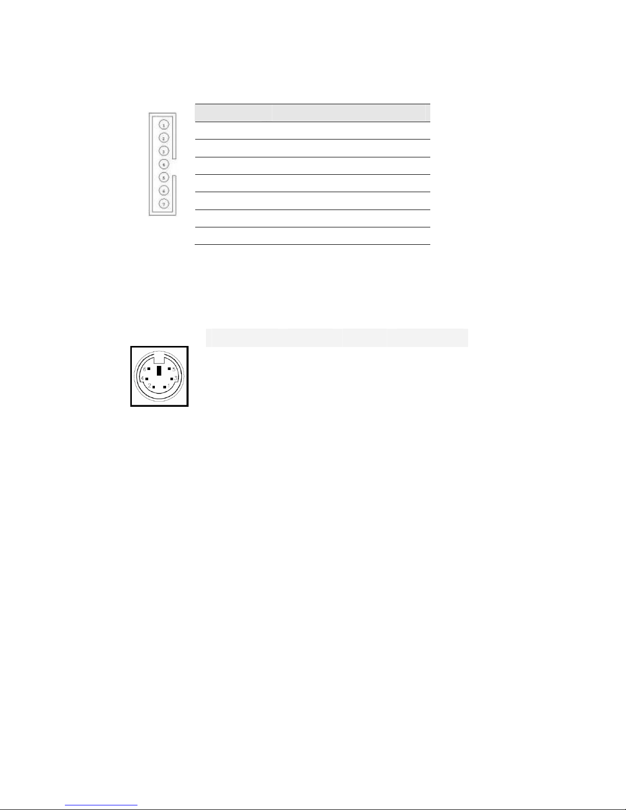
2.5.3 CON3: Digital Panel Backlight Inverter Power
2.5.4 PSKBM1: PS2 Keyboard/Mouse Connector
Pin Number
Signal Name
1 +12V
2 +12V
3 +12V
4 GND
5 Black Light Control
6 GND
7 Black Light EN 5V
Signal Name Keyboard Mouse Signal Name
Keyboard data 1 1 Mouse data
N.C. 2 2 N.C.
GND 3 3 GND
5V 4 4 5V
Keyboard clock 5 5 Mouse clock
N.C. 6 6 N.C.
IA31 Motherboard User Manual
14
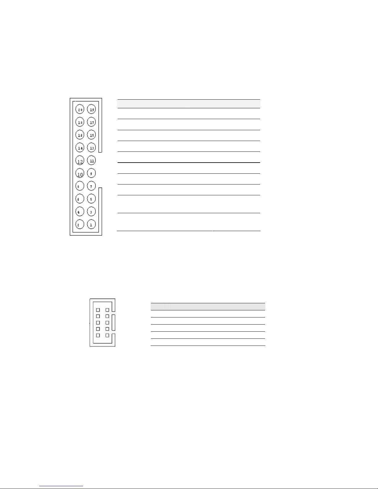
2.5.5 CON12: D-SUB Dual Output
CON12 is connecter for COM1 and COM2. COM1 is from pin 11 pin to pin 20),
COM2 is from pin 1 to pin10.
2.5.6 CON16: D-SUB Dual Output
The CON16 is COM3 port, support standard RS-232.
Pin No. SYMBOL Pin No.
SYMBOL
20
GND
19
GND
18
NRI1A
17
NDTR1A
16
NCTS1A
15
NTXD1A
14
NRTS1A
13
NRXD1A
12
NDSR1A
11
NDCD1A
10
GND
9
GND
8
NRIA
7
NDTRA
6
NCTSA
5
NTXDA
4
NRTSA
3
NRXDA
2
NDSRA
1
NDCDA
Pin SYMBOL
Pin SYMBOL
2 NDSR2 1 NDCD2
4 NRTS2 3 NSIN2
6 NCTS2 5 NSOUT2
8 NRI2 7 NDTR1A
10
GND 9 GND
1
3
5
7
9
2
4
6
8
10
IA31 Motherboard User Manual
15
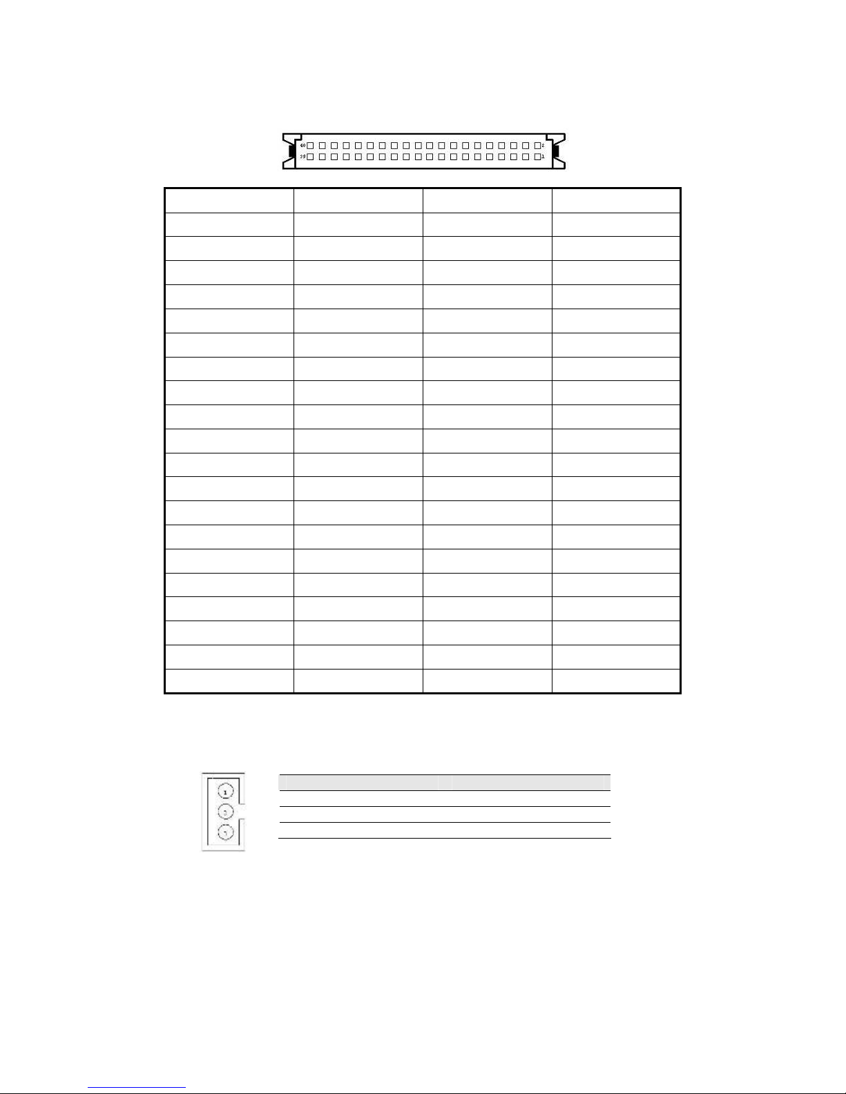
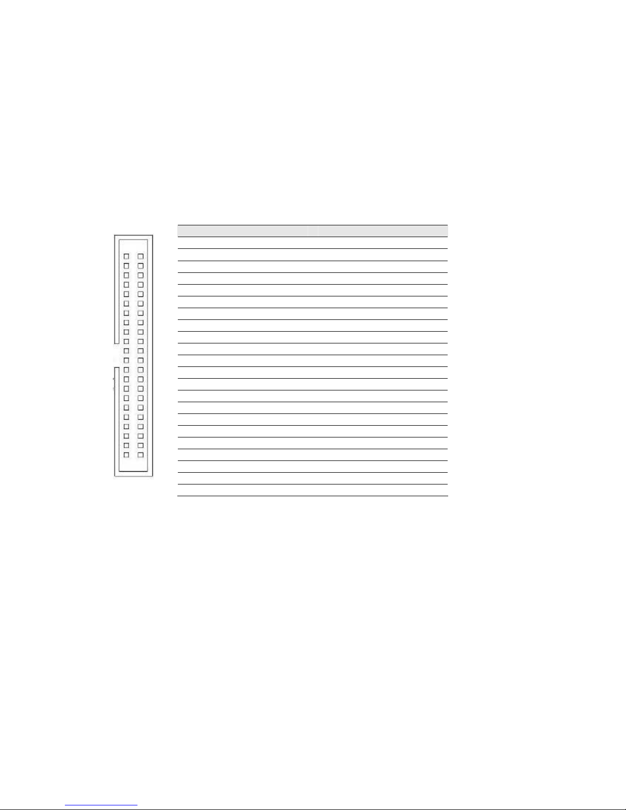
2.5.7 IDE1: IDE Connector
Pin N
o. SYMBOL
Pin N
o. SYMBOL
1 RESET 2 GND3
3 DD7 4 DD8
5 DD6 6 DD9
7 DD5 8 DD10
9 DD4 10 DD11
11 DD3 12 DD12
13 DD2 14 DD13
15 DD1 16 DD14
17 DD0 18 DD15
19 GND1 20 NC
21 DREQ 22 GND4
23 DIOW# 24 GND5
25 DIOR# 26 GND6
27 IO_RDYD 28 CSEL
29 DACK# 30 GND7
31 IRQ 32 IOCS16#
33 DA1 34 CBL_ID#
35 DA0 36 DA2
37 DCS#1 38 DCS#3
39 DASP# 40 GND8
41 +5V1 42 +5V2
43 GND 44 NC
1 2
44
IA31 Motherboard User Manual
16
2.5.8 USB1: USB Pin Header
2.5.9 NB_FAN1/CPU_FAN1: Fan Connector
CPU_FAN1 NB_FAN1
2.5.10 PANEL1: Front Panel System Function Connector
Pin Number Signal Name Pin Number Signal Name
2 USBVCC 1 USBVCC
4 USB_P- 3 USB_P-
6 USB_P+ 5 USB_P+
8 GND 7 GND
Pin SYMBOL
Pin SYMBOL
2 HD_LED+ 1 PW_LED+
4 HD_LED- 3 PW_LED6 RT_BT1 5 PW_BT1
8 RT_BT2 7 PW_BT2
10
5VSB 9 RSEV
1
4
5
7
3
8
6
2
IA31 Motherboard User Manual
17
2.5.11 Panel L2: System Function Connector
JST-B13B-PH-KL
Pin No.
SYMBOL
1 PWR Button
2 Ground
3 Reset Button
4 HD Led
5 5V
6 HD LED#
7 PWR LED
8 5V
9 Ground
10* Volume Control +
11* Volume Control 12* Brightness Control +
13* Brightness Control -
*Not Default Setting
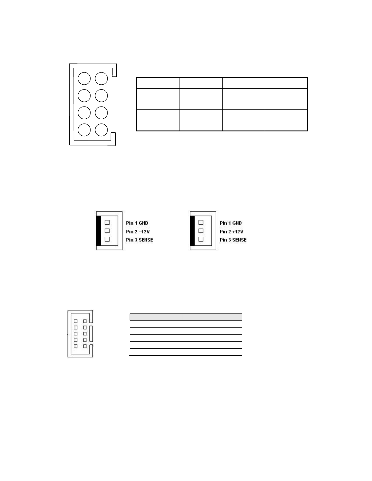
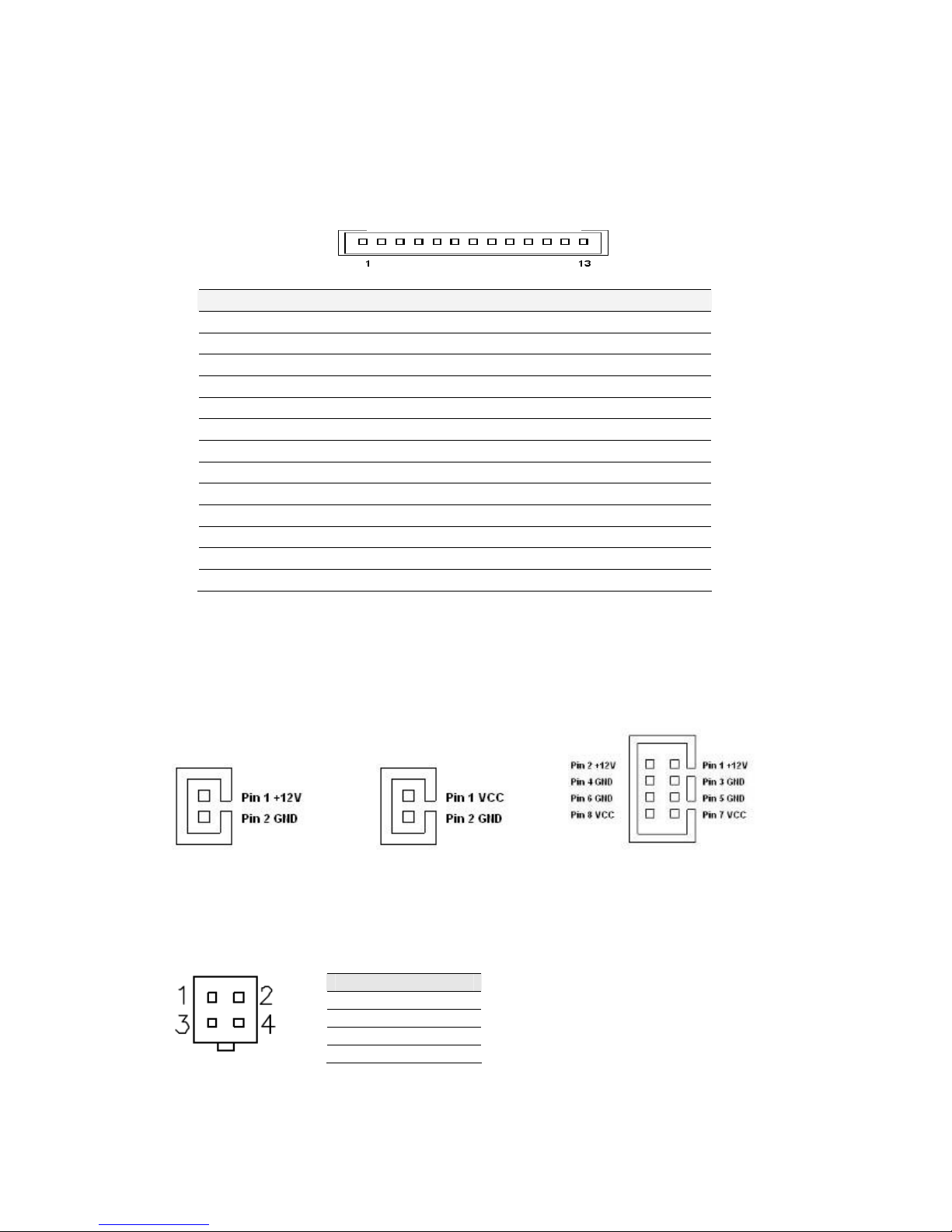
2.5.12 CON10/CON11/CON19: External Power
CON10 CON11 CON19
2.5.13 ATX12V 1: 12V DC Connector
Pin SYMBOL
1 Ground
2 Ground
3 +12V
4 +12V

IA31 Motherboard User Manual
18
2.5.14 CON6: Digital I/O Connector
Pin SYMBOL
Pin SYMBOL
2 Vcc 1 GND
4 Out1 3 Out3
6 Out0 5 Out2
8 IN1 7 IN3
10
IN0 9 IN2
2
4
6
8
10
1
3
5
7
9
 Loading...