

Euro CLS I570 User Manual
I570 Motherboard
Mini-ITX Fan SBC w/ Intel®Socket
FC-PGA 478/FC-BGA 479 CPU,
VGA, LCD, Giga Ethernet, Mini-PCI
and PCI Slot Interface.
USER MANUAL Version 1.0
ZI de St Génault 16 rue Jean Mermoz 91080 Courcouronnes France Tél : +33 (0) 1 60 78 97 93 Fax : +33 (0) 1 60 79 14 88 Web : www.eurocls.com

I570 Motherboard User Manual
II
FCC Statement
This device complies with part 15 FCC rules. Operation is subject to
the following two conditions :
This device may not cause harmful interference.
This device must accept any interference received including
interference that may cause undesired operation.
This equipment has been tested and found to comply with the limits for a class "a"
digital device, pursuant to part 15 of the FCC rules. These limits are designed to
provide reasonable protection against harmful int erference when the equipment is
operated in a commercial environment. This equipment generates, uses, and can
radiate radio frequency energy and, if not installed and used in accordance with the
instruction manual, may cause harmful interference to radio c ommunications.
Operation of this equipment in a residential area is likely to cause harmful
interference in which case the user will be required to correct the interference at hi m
own expense.

I570 Motherboard User Manual
III
Copyright Notice
ALL RIGHTS RESERVED. No part of this document may be reproduced, copied,
translated, or transmitted in any form or by any means, electronic or mechanical, for
any purpose, without the prior written permission of the original manufacturer.
Trademark Acknowledgement
Brand and product names are trademarks or registered trademarks of their respective
owners.
Disclaimer
We reserve the right to make changes, without notice, to any product, including
circuits and/or software described or contained in this manual in order to improve
design and/or performance. We assume no responsibility or liability for the use of the
described product(s), conveys no license or title under any patent, copyright, or masks
work rights to these products, and makes no representations or warranties that these
products are free from patent, copyright, or mask work right infringement, unless
otherwise specified. Applications that are described in this manual are for illustration
purposes only. We make no representation or warranty that such application will be
suitable for the specified use without further testing or modification.
Warranty
We warrant that each of its products will be free from material and workmanship
defects for a period of one year from the invoice date. If the customer discovers a
defect, We will, at its option, repair or replace the defective product at no charge to
the customer, provided it is returned during the warranty period of one year, with
transportation charges prepaid. The returned product must be properly packaged in its
original packaging to obtain warranty service.
If the serial number and the product shipping data differ by over 30 days, the
in-warranty service will be made according to the shipping date. In the serial numbers
the third and fourth two digits give the year of manufacture, and the fifth digit means
the month (e. g., with A for October, B for November and C for December).
For example, the serial number 1W07Axxxxxxxx means October of year 2007.

I570 Motherboard User Manual
IV
Packing List
Before using this Motherboard, please make sure that all the items listed below are
present in your package :
I570 Motherboard
I570 SBC User Manual
HDD IDE Cable
User’s Manual & Driver CD
If any of these items are missing or damaged, contact your distributor or sales
representative immediately.
Customer Service
We provide service guide for any problem as follow steps:First, visit the website at to
find the update information about the product. Second, contact with your distributor,
sales representative, or our customer service center for technical support if you need
additional assistance. You may have the following information ready before you call:
Product serial number
Peripheral attachments
Software (OS, version, application software, etc.)
Description of complete problem
The exact wording of any error messages
In addition, free technical support is available from our engineers every business day.
We are always ready to give advice on application requirements or specific
information on the installation and operation of any of our products. Please do not
hesitate to call or e-mail us.

I570 Motherboard User Manual
V
Safety Precautions
Warning!
Always completely disconnect the power cord from your chassis
whenever you work with the hardware. Do not make connections
while the power is on. Sensitive electronic components can be
damaged by sudden power surges. Only expe rienced electronic
personnel should open the PC chassis.
Caution!
Always ground yourself to remove any static charge before
touching the CPU card. Modern electronic devices are very
sensitive to static electric charges. As a safety precaution, use a
grounding wrist strap at all times. Place all electronic components
in a static-dissipative surface or static -shielded bag when they are
not in the chassis.
7

I570 Motherboard User Manual
VI
Safety and Warranty
1. Please read these safety instructions carefully.
2. Please keep this user's manua l for later reference.
3. Please disconnect this equipment from any AC outlet before cleaning. Do not use
liquid or spray detergents for cleaning. Use a damp cloth.
4. For pluggable equipment, the power outlet must be installed near the equipment
and must be easily accessible.
5. Keep this equipment away from humidity.
6. Put this equipment on a reliable surface during installation. Dropping it or letting
it fall could cause damage.
7. The openings on the enclosure are for air convection. Protect the equipment from
overheating. DO NOT COVER THE OPENINGS.
8. Make sure the voltage of the power source is correct before connecting the
equipment to the power outlet.
9. Position the power cord so that people cannot step on it. Do not place anything
over the power cord.
10. All cautions and warnings on the equipment should be noted.
11. If the equipment is not used for a long time, disconnect it from the power source
to avoid damage by transient over -voltage.
12. Never pour any liquid into an opening. This could cause fire or electrical shock.
13. Never open the equipment. For safety reasons, only qualified service personnel
should open the equipment.
14. If any of the following situations arises, get the equipment checked by service
personnel:
A. The power cord or plug is damaged.
B. Liquid has penetrated into t he equipment.
C. The equipment has been exposed to moisture.
D. The equipment does not work well, or you cannot get it to work according to
the user’s manual.
E. The equipment has been dropped and damaged.
F. The equipment has obvious signs of breakage.
15. Do not leave this equipment in an uncontrolled environment where the storage
temperature is below -20° C (-4°F) or above 60° C (140° F). It may damage the
equipment.

I570 Motherboard User Manual
VII
Revision History
Version
Date
Note
Author
0.1
2008.01.16
Initial Draft
Aladin Huang
1.0
2008.02.25
First version
Aladin Huang

I570 Motherboard User Manual
VIII
Contents
CHAPTER 1 GENERAL INFORMATION ................................ .....1
1.1 INTRODUCTION ................................ ................................ ............ 1
1.2 FEATURE ................................ ................................ ..................... 1
1.3 MOTHERBOARD SPECIFICATIONS................................ .................. 2
1.4 FUNCTION BLOCK ................................ ................................ ....... 3
1.5 BOARD DIMENSIONS ................................ ................................ .... 4
CHAPTER 2 INSTALLATIONS ................................ ...................... 6
2.1 MEMORY MODULE(DIMM)INSTALLATION .............................. 6
2.2 I/O EQUIPMENT INSTALLATION ................................ .................... 6
2.3 JUMPERS AND CONNECTORS ........................................................ 8
2.4 JUMPER SETTING ................................ ................................ ......... 9
2.5 CONNECTORS AND PIN ASSIGNMENT ................................ .......... 12
CHAPTER 3 GRAPHIC DRIVER INSTA LLATION................... 23
3.1 GRAPHIC DRIVER INSTALLATION ................................ ................ 23
CHAPTER 4 CHIPSET DRIVER INSTA LLATION .................... 28
4.1 CHIPSET DRIVER INSTALLATION ................................ ................. 28
CHAPTER 5 ETHERNET DRIVER INSTALLATION ................. 33
5.1 INSTALLATION OF ETHERNET DRIVER ................................ ......... 33
CHAPTER 6 AUDIO DRIVER INSTALL ATION ........................ 37
6.1 INTRODUCTION ................................ ................................ .......... 37
6.2 INSTALLATION OF AUDIO DRIVER................................ ............... 37
CHAPTER 7 AWARD BIO S INSTALLATION .............................. 40
7.1 BIOS INTRODUCTION ................................ ................................ 40
7.2 BIOS SETUP................................ ................................ .............. 40
7.3 STANDARD CMOS SETUP ................................ .......................... 41
7.4 ADVANCE BIOS FEATURE................................ .......................... 43
7.5 ADVANCED CHIPSET FEATURE ................................ ................... 46
7.6 INTEGRATED PERIPHERALS ........................................................ 49
7.7 PNP / PCI CONFIGURATION ................................ ........................ 52
7.8 POWER MANAGEMENT SETUP................................ ..................... 53
7.9 PC HEALTH STATUS ................................ ................................ ... 56
7.10 LOAD FAIL-SAFE DEFAULTS ................................ ....................... 57

I570 Motherboard User Manual
IX
7.11 LOAD OPTIMIZED DEFAULTS................................ ..................... 57
7.12 SET SUPERVISOR PASSWORD ................................ ..................... 57
7.13 SAVE & EXIT SETUP ................................ ................................ . 57
7.14 EXIT WITHOUT SAVING ................................ ............................ 57
NOTE: DIGITAL I/O SA MPLE CODE................................ .............58

I570 Motherboard User Manual
1
General Information
This chapter includes I570 Motherboard background
information.
Sections include:
Introduction
Feature
Motherboard Specification
Function Block
Board Dimensions
C H A P T E R
1

I570 Motherboard User Manual
1
Chapter 1 General Information
1.1 Introduction
I570 SBC is equipped with Intel 85 5GME North Bridge and In tel ICH4 South
Bridge which are designed for use with Intel’s mobile platform . Intel’s 855GME
platform delivers the performance and high scalability cutting -edge embedded
computing application.
In peripheral connectivity, I570 SBC with one PCI slot and Mini-PCI I/O ports,
two PATA connectors, and six Hi-Speed USB connectors.
Thus, I570 SBC is designed to satisfy most of the applications in the industrial
computer market, such as Gaming, POS, KIOSK, Industrial Automation, and
Programmable Control System . It is a compact design to meet the demanding
performance requirements of today’s business and industrial applications.
1.2 Feature
Mini-ITX Form Factor ( 170mm x 170mm)
Supports Socket FC-PGA 478/FC-BGA 479 Intel® Pentium M / Celeron M
processors
System memory up to 1 GB DDR 200/266/333, 1xDIMM
Integrated Intel 855GME + ICH4 Chipset
Intel® extreme Graphics 2 Integrated 64MB shared supports VGA
Dual Gigabit Ethernet ( Dual Fast Ethernet o ptional)
1 x PCI slot, 1 x Mini PCI, 4 x COM, 6 x USB2.0, 1 x CF(Optional)
2 x PATA( 1 x 40 pins IDE1 1 x 44 pins IDE2 )
I570 Motherboard User Manual
2
1.3 Motherboard Specifications
CPU Type
Intel l® Pentiun M/ Celeron M Processor
CPU FSB
400 MHz
CPU Socket
Intel Socket FC-PGA 478/ FC-BGA 479
Chipset
Intel 855GME / ICH4
BIOS
Award 4Mbit Flash
VGA
Intel® extreme Graphics 2
64MB shared with system memory
LVDS
Intel® 82855GME built in single- or Dual-channel panel
support up to 1600 x 1200, 24bit
LAN
2 x Giga LAN (Dual Realtek RTL8110SCL Controller )
2 x Fast LAN(Dual Realtek RTL8110S Controller) (optional)
Memory Type
1 x DDR DIMM socket, supports up to 1GB DDR
200/266/333 SDRAM
LPC I/O
Winbond W83627EHG integrated hardware monitoring
Keyboard/Mouse
2 x PS/2 Keyboard/Mouse co nnectors
IDE Interface
Dual channels; supports Ultra DMA 33/66/100
Sound
Realtek ALC655 (Line-in, Line-out, Mic in)
USB
6 ports, USB 2.0 (4 x USB Connector, 2 x USB pin-header )
Edge Connectors
1 x +12V DC-IN Jack
2 x PS/2 connector for keyboard/mouse
2 x DB9 for COM3 & COM4
1 x VGA out connector + 1 x DB9 for COM1
2 x Gigabit LAN RJ-45 + 1 x dual USB stack connector
1 x Audio Jack for Audio (Line-in, Line-Out, Mic-in)
On Board
Pin-Header
Connectors
1 x 44 pins box-header
1 x 40 pins box-header
1 x 10pins pin-header for Front Panel(2x5)
1 x 3pins pin-header for CPU Fan
1 x 3pins pin-header for System FAN
1 x 8pins pin-header for 5V/12V external power
1 x 4pins connector for 12V/5V external power
1 x 2pins pin-header for 5V external power
1 x 2pins pin-header for 12V external power
1 x 4pins ATX 12V connector
2 x 2pins pin-header for Front Audio (with Amp.)
1 x 10pins pin-header for Front Audio( without Amp.)(2x5)
1 x 10pins pin-header for USB 5/6(2x5)
1 x 10pins pin-header for COM2(RS232)(2x5)
1 x 40pins DF13 Connector for LVDS
1 x 3pins digital panel backlight brightness controller
1 x 7pins digital panel backlight controller
1 x 10pins pin-header for DIO(2x5)
Power Connector
Input: 4-pin ATX 12V Power input
Expansion Slots
1 x PCI, 1 x Mini-PCI
Form Factor
Mini-ITX
Dimensions
170mm x 170mm
Mechanical &
environmental
Operating temperature: 0 deg. C to 60 deg. C
Operating Humidity: 3 0 ~ 90% Relative humidity,
non-condensing
Certification: CE, FCC, RoHS
I570 Motherboard User Manual
3
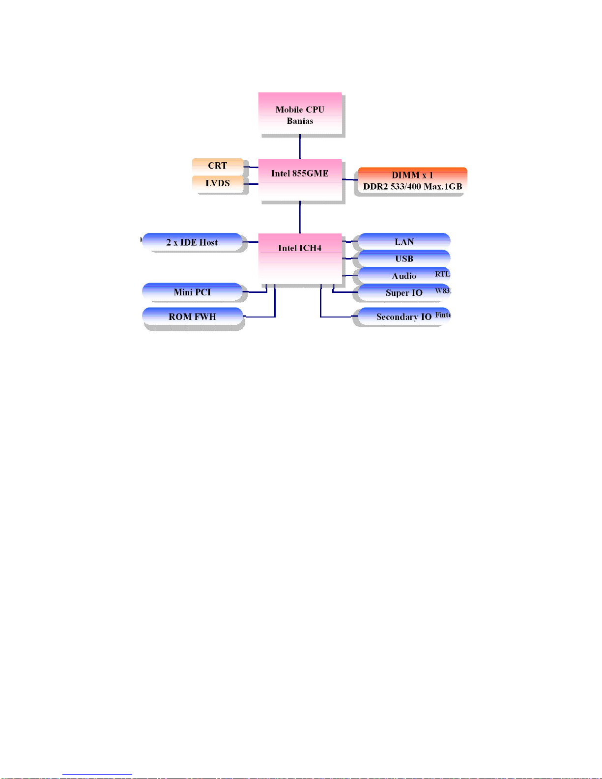
1.4 Function Block
Mobile CPU
Banias
Intel 855GME
Pentium M /
Celeron M
Processor
FSB 400
66MHz Hub Interface 1.5
CRT
LVDS
1600*1200
18bit/Dual CH
DIMM x 1
DDR2 533/400 Max. 1GB
2 x IDE Host
ATA100
Mini PCI
33MHz
LAN
USB
2x 1GB/s
480MB/s
Audio
Super IO
Secondary IO
WW8833226677EEHHG
G
FFiinntteekk8811221166D
D
ROM FWH
RRTTLLAALLCC66555
5
Intel ICH4
I570 Motherboard User Manual
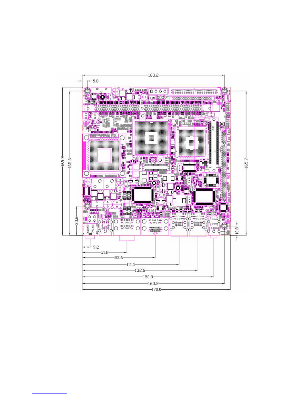
4
1.5 Board dimensions

I570 Motherboard User Manual
5
Installations
This chapter provides information on how to use the
jumps and connectors on I570 Motherboard.
The Sections include:
Memory Module Installation
I / O Equipment Installation
Setting the Jumpers
Connectors on I570 Motherboard
C H A P T E R
2
I570 Motherboard User Manual
6
Chapter 2 Installations
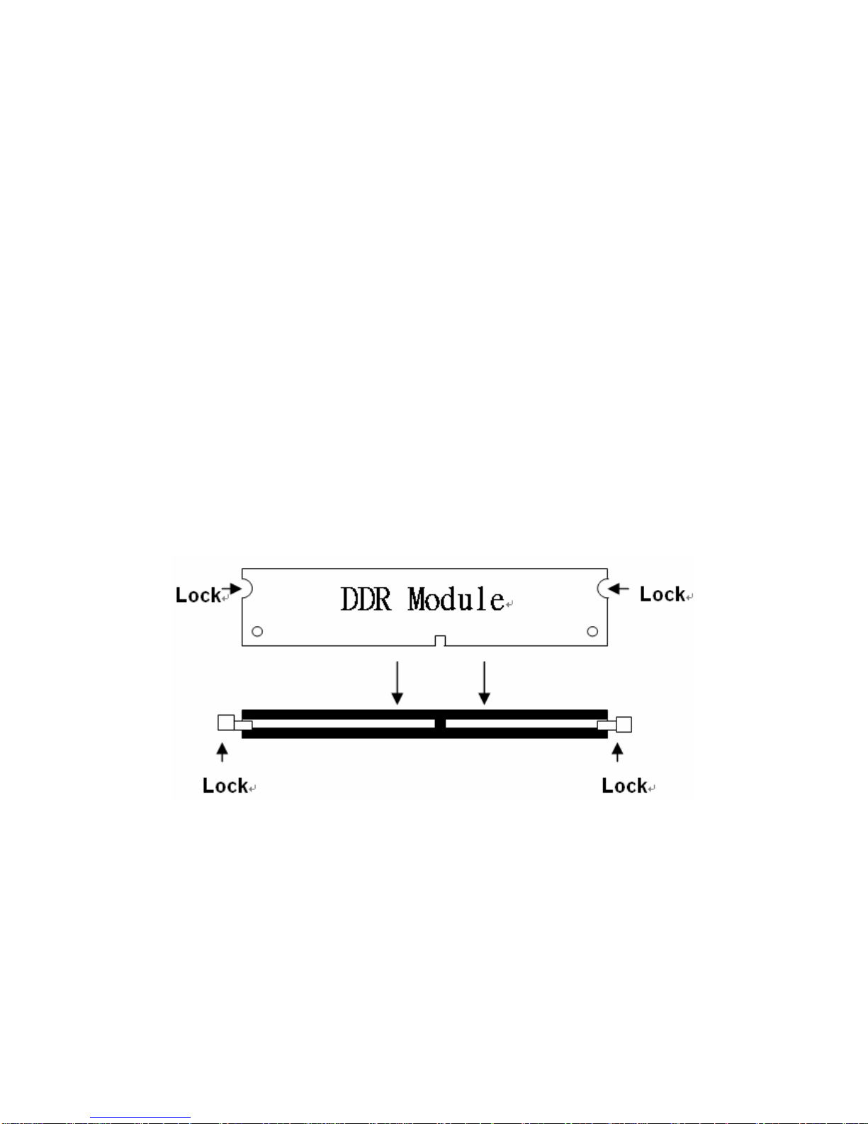
2.1 Memory Module(DIMM)Installation
I570 motherboard supports one DDR memory socket for a maximum total memory of
1GB in DDR memory type.
2.1.1 Installing and Removing Memory Modules
To install the DDR modules, locate the memory slot on the board and perform the
following steps:
1. Hold the DDR module so that the key of the DDR module align with those on
the memory slot.
2. Gently push the DDR module in an upright position until the clips of the slot
close to hold the DDR module in place when the DDR module touches the
bottom of the slot.
3. To remove the DDR module, press the clips with both hands.
2.2 I/O Equipment Installation
2.2.1 12V DC-IN
The Motherboard allows plugging 12V DC-IN jack on the board without another
power module converter under power consumption by Inte l FC-PGA 478/ FC-BGA
479 processor in 855GME with ICH4 chipset.
2.2.2 PS/2 Keyboard and PS/2 Mouse

I570 Motherboard User Manual
7
The Motherboard provides two PS/2 interface. The PS/2 connector supports Keyboard
and Mouse. In other cases, especially in embedded applications, a mouse is not used.
Therefore, the BIOS standard setup menu allows you to select* “All, But Keyboard”
under the “Halt On”. This allows no -keyboard operation in embedded system
applications without the system halting under POST.
2.2.3 Serial COM ports
Three RS-232 connectors build in the rear I/O. Fourth optional COM ports support
RS-232. When an optional touch -screen is ordered with PPC, serial com port can
connect to a serial or an optional touch -screen. One optional COM port supports
RS232/422/485 choice through jumper sett ing.
2.2.4 Internal VGA
The Motherboard has one VGA port that can be connected to an external CRT/ LCD
monitor. Use VGA cable to connect to an external CRT / LCD monitor, and connect
the power cable to the outlet . The VGA connector is a standard 15 -pin D-SUB
connector.
2.2.5 Ethernet interface
The Motherboard is equipped with Dual Realtek RTL8110SCL or ( Realtek
RTL8110S 10/100 Mbps ) chipsets which is fully compliant with the PCI 10/100 /1000
Mbps Ethernet protocol compatible. It is supported by major network operat ing
systems. The Ethernet port s provide two standard RJ-45 jacks.
2.2.6 USB ports
Six USB devices (four with pin headers) may be connected to the system though an
adapter cable. Various adapters may come with USB ports. USB usually connect the
external system to the system. The USB ports support hot plug -in connection.
Whatever, you should install the device driver before you use the device.
2.2.7 Audio Jack ( Pin-header)
The Audio 5.1 channel capabilities are provided by a Realtek ALC655 chipset
supporting digital audio outputs. The audio interface includes Mic-in,: line-in and
line-out.
I570 Motherboard User Manual
8
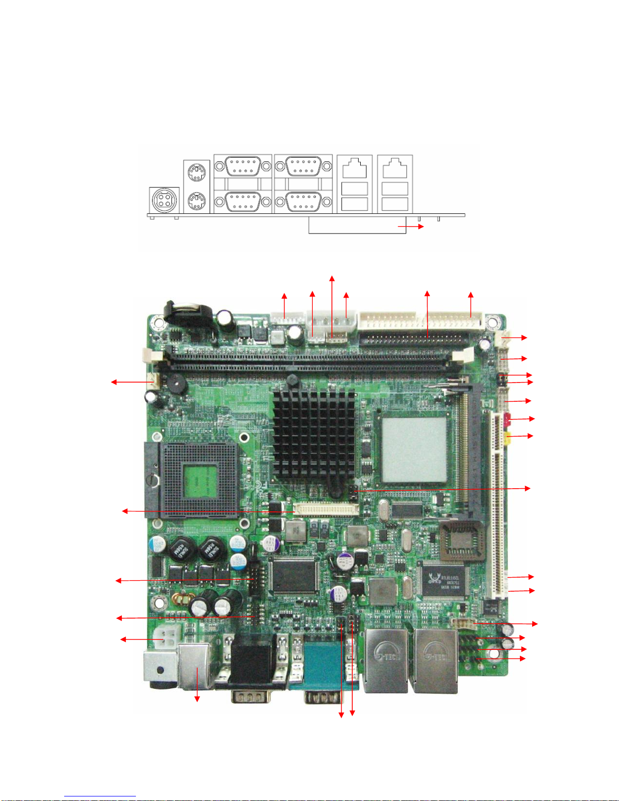
2.3 Jumpers and Connectors
TOP
BOTTOM
CF Card Slot(Optional)
NB_FAN1
Panel 1
JP2
JP3
USB1
CON9
CON8
J5J6Audio
Line-in
Line-out
Mic-in
JP5
JP4
+12 V DC-IN
CON5
CON6
CON4
CON2
CPU_FAN1
CON3
JP1
J6
CON7
IDE1
IDE2
CF slot ( Optional)
LAN1
LAN2
COM1
COM4
COM3
VGA
PS/2
DC Jack
PSKBM1
CON1
CON10
USBLAN1
USBLAN2
PWIN1
I570 Motherboard User Manual
9
2.4 Jumper Setting
A pair of needle-nose pliers may be helpful when working with jumpers. If you have
any doubts about the best hardware configuration for your application, contact your
local distributor or sales representative before you make any changes. Generally, you
simply need a standard cable to make most connections.
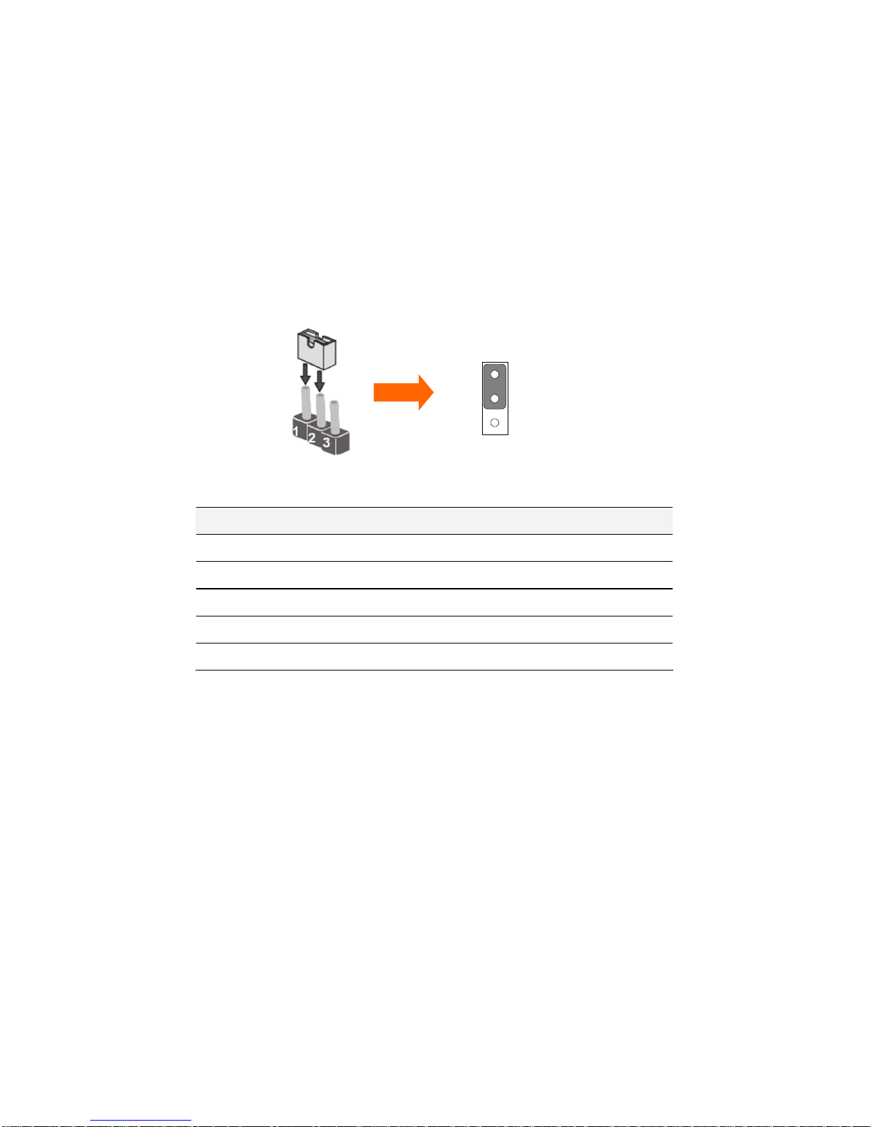
The jumper setting diagram is as below. If a jumper shorts pin 1 and pin 2, the setting
diagram is shown as the right one.
The following tables list the function of each of the board's jumpers.
Label
Function
Note
JP2
Clear CMOS
3x1 header , pitch 2.0mm
JP3
CF Card Priority
3x1 header , pitch 2.0mm
JP4
RS232 / RS422 / RS485 Selector
2x3 header , pitch 2.0mm
JP5
RS232 / RS422 / RS485 Selector
3x4 header , pitch 2.0mm
CON4
LVDS VOLTAGE
2x3 header , pitch 2. 0mm
1
2
3
I570 Motherboard User Manual
10
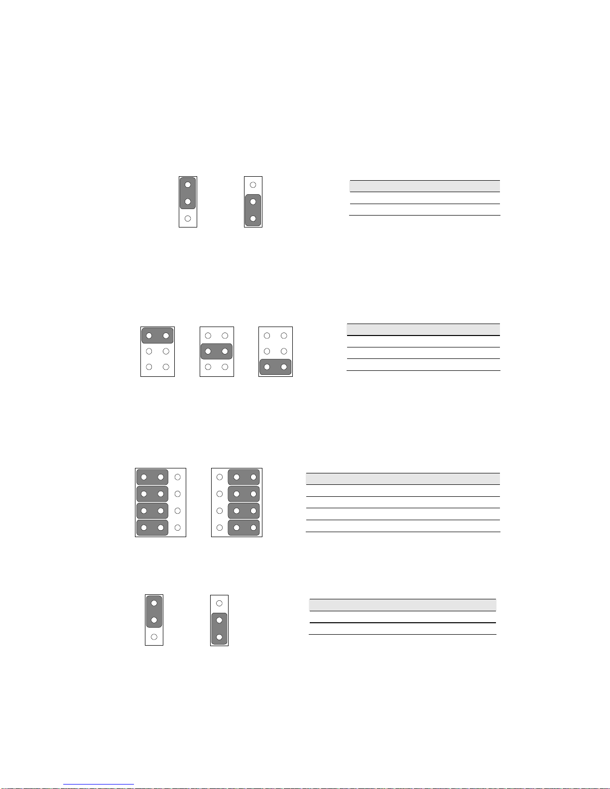
2.4.1 JP2: Clear CMOS
User must make sure the power supply to turn off the power supply before setting
Clear CMOS. Users remember to setting jumper back to Normal before turning on the
power supply. Default: 1 short 2.
JP4 : COM1 RS232 / RS422 / RS485 Function Selector
The jumper can be configured to operate COM1 in RS-232/422/485 mode. And the
setting must be cooperated with the 2.4.2 settings. Default 1 short 2.
2.4.2 JP5: RS232 / RS422 / RS485 Selector
The jumper can be configured to operate COM1 in RS-232/422/485 mode. And the
setting must be cooperated with JP4 settings.
2.4.3 JP3: CF Card Priority
JP3 can be configured to operate CF Card Priority in Master/Slave mode.
Pin No.
Functions
1 Short 2
Normal
2 Short 3
Clear CMOS
Pin No.
Functions
1 Short 2
RS232
3 Short 4
RS485
5 Short 6
RS422
RS232
RS422/485
1-2
2-3
4-5
5-6
7-8
8-9
10-11
11-12
Pin No.
Functions
1 Short 2
Master
2 Short 3
Slave
1
2
3
Normal
1
2
3
Clear CMOS
RS232
1
3
5
2
4
6
RS485
1
3
5
2
4
6
RS422
1
3
5
2
4
6
RS232
1
4
7
10
3
6
9
12
RS422/485
1
4
7
10
3
6
9
12
1
2
3
Master
1
2
3
Slave

I570 Motherboard User Manual
11
2.4.4 CON4: LCD Panel Voltage Select
CON4 can be configured to operate in 3.3Volts / 5Volts / 12Volts mode.
Pin No.
Functions
1 Short 2
3.3Volts Selected
3 Short 4
5Volts Selected
5 Short 6
12Volts Selected
5Volts
1
3
5
2
4
6
3.3Volts
1
3
5
2
4
6
12Volts
1
3
5
2
4
6
 Loading...