

Eurocal SENATOR, COUNTRYMAN Installation & User Manual
Installation & Users Guide
SENATOR
and
COUNTRYMAN
System- Boilers

1
INTRODUCTION Page
- WARRANTY 2
USER INSTRUCTIONS
- BOILER OPERATION 3
- SWITCHING THE BOILER ON 3
- BOILER CONTROLS 4
- SWITCHING THE BOILER OFF 5
- BURNER LOCKOUT 5
- RESTARTING AFTER LOCKOUT 5
- RESTART 6
INSTALLATION
- REGULATIONS 7
- WATER CONNECTIONS 7
- BOILER LOCATION 8
- SERVICE REQUIREMENTS 9
- THE HEARTH 9
- CONTROL PANEL 9
- PREFORMED PIPE WORK 10
- SEALED SYSTEM 10
- PLASTIC PIPE 10
- CAPACITIES OF EXPANSION VESSEL 11
- EXPANSION VESSEL SIZING 11
- WARNING SEALED SYSTEM 11
- FILLING SYSTEM 11
- SENATOR CONVENTIONAL FLUE INSTALLATION 12
- BALANCED FLUE INSTALLATION (INTERNAL) 13-21
- CONNECTING OIL SUPPLY 21-22
- ELECTRICAL CONNECTION (INTERNAL & EXTERNAL) 23
- WIRING DIAGRAM (INTERNAL) 23
TECHNICAL DATA
- BOILER SPECIFICATIONS 24-25
- COMMISSIONING INSTRUCTIONS 26
- SERVICING INSTRUCTIONS 27
- FAULT FINDING COMBUSTION 28
- PARTS LIST 29
- BURNER SETTINGS 30
Issue No.1 12/11/04

INTRODUCTION
Thank you for choosing the INTERNAL or EXTERNAL COUNTRYMAN COMBI oil boiler please
read the following carefully.
To the installer
This manual must be left with the householder by the installer who will instruct the user on
the boiler operation.
To the user
Please read the user section of this manual to familiarize yourself with the boiler operation.
WARRANTY
WARRANTY FOR YOUR BOILER MUST MEET THE FOLLOWING
CONDITIONS OR YOUR WARRANTY MAY BE INVALID
Warranty on the Heat Exchanger: 5 Years
Warranty on Burner and Controls: 2 years
CONDITIONS OF WARRANTY:
1.Boiler MUST BE installed by an OFTEC registered engineer, if not permission will be
required by building control.
2.Boiler MUST BE commissioned after installation by an OFTEC registered engineer.
3.Boiler MUST BE serviced every 12 months after installation by an OFTEC registered
engineer.
4.Installer MUST COMPLETE an Installation/Commissioning Form, which will be found
along with your manual and this must then be returned to the address on the warranty
form. Failure to return this form, may invalidate your warranty.
2

USER INSTRUCTIONS
3
BOILER OPERATION
The Boiler Control Thermostat responds to the temperature of the water within the boiler
and switches power to the burner when heat is required.
The burner has an independent control system which regulates the firing and (shut-off)
of the burner.
Automatic firing of the burner will occur when the water temperature within the boiler
falls below the control thermostat set point which will continue to run until the water
temperature rises to the temperature (recommended) set on the boiler control
thermostat.
SWITCHING THE BOILER ON
- Check there is water in the system.
- Check radiator valves are on.
- Turn on oil supply.
- Switch electrical supply to the boiler on (including time clock ) and then set the boiler
control thermostat to recommended setting.
Boiler Control
Thermostat

BOILER CONTROLS
BOILER CONTROL THERMOSTAT
The temperature of the water within the boiler is controlled and maintained by the Boiler
Control Thermostat located on the boiler control panel.
TEMPERATURE SETTINGS:
The Boiler Control Thermostat has a range of 50˚C to 80˚C. The recommended setting for
the boiler control thermostat is:
WINTER
Heating and hot water supply 80˚C
SUMMER
Domestic hot water supply 65˚C
It is not recommended to operate the boiler with a thermostat setting of less than 60˚C,
as this will precipitate corrosion, thus reducing the life of the boiler.
HIGH LIMIT STAT INDICATOR:
The high limit lockout will occur when the water within the boiler is or has overheated e.g.
reached a temperature above that set on the high limit thermostat.
TO RESET THE BOILER
When the boiler has had time to cool, the manual reset button (coloured red) on the
control panel will need to be pressed in to reset. If the high limit thermostat continues to
trip, contact your installer as there may be a fault with the central heating system.
LOCKOUT INDICATOR: RED
The lock out indicator will illuminate when the burner has failed to fire, e.g. No fuel or an
electrical fault.
4
Reset Button
Burner Control Box

SWITCHING THE BOILER OFF
The boiler can be turned off by turning the rocker switch, located on the underside of
control panel, to the OFF position.
PLEASE NOTE: For longer periods of shutdown e.g. While away on holiday, switch OFF the
mains (electrical supply) and turn OFF the OIL supply.
If shutdown occurs during cold weather ensure boiler is protected against frost damage.
BURNER LOCKOUT
The burner has an independent control system (Burner Control Box); this includes a flame
detector (Photocell) which senses the presence of a flame. In the event of flame failure,
the burner Control Box activates a second re-ignition sequence. Should the Photocell not
detect a flame presence within 15 seconds the burner goes to LOCKOUT and shuts down.
Continued LOCKOUTS are a result of a fault in the operation of the boiler and can be
attributed to following examples:
- An interruption of the fuel supply .
- Electrical Supply fault e.g. Extreme low voltage.
- Failure of a Burner component.
- A fault within the heating system .
- Burner combustion not being correct.
The Burner Reset button on the Control Box and the red Lockout Indicator on the boiler
control panel illuminates to indicate that a lockout has occurred.
In the event of the Burner locking out, do not attempt to restart the Burner by pressing the
Reset Button on the Burner Control Box for at least 2 minutes. A Bi-metallic timer within the
Control Box has a minimum cooling time of 45 seconds thus the 2 minute interval will
ensure that this Bi-metallic timer has cooled and is therefore in a position where it may be
reset
RESTARTING AFTER LOCKOUT
When lockout has occurred, inspect for any obvious causes e.g. oil leaks.
Also check the fuel line from the tank to the boiler and that any oil shut off valve has not
been inadvertently closed.
5
RESTART
- Check there is adequate oil in the storage tank.
- Check oil supply valves are open.
- Switch on heating system (e.g. Time clock).
- Depress the red Burner Reset Button on the burner Control Box, which will be illuminated.
Both Burner Reset Button (illuminated) and the lockout Indicator on the Control P anel will go
out and the burner will commence the ignition start sequence. After 15 seconds the Burner
should fire normally.
PLEASE NOTE: Should the Burner not start, both lockout indicator, on the Control Panel and
Burner Reset Button will illuminate again.
- Wait at least 3 minutes and depress the Burner Rest Button again.
Failure to start a second time indicates a fault requiring attention.
In the event of a second failure to start:
- Switch off electrical supply.
- Call service engineer.
6
Burner Reset Button
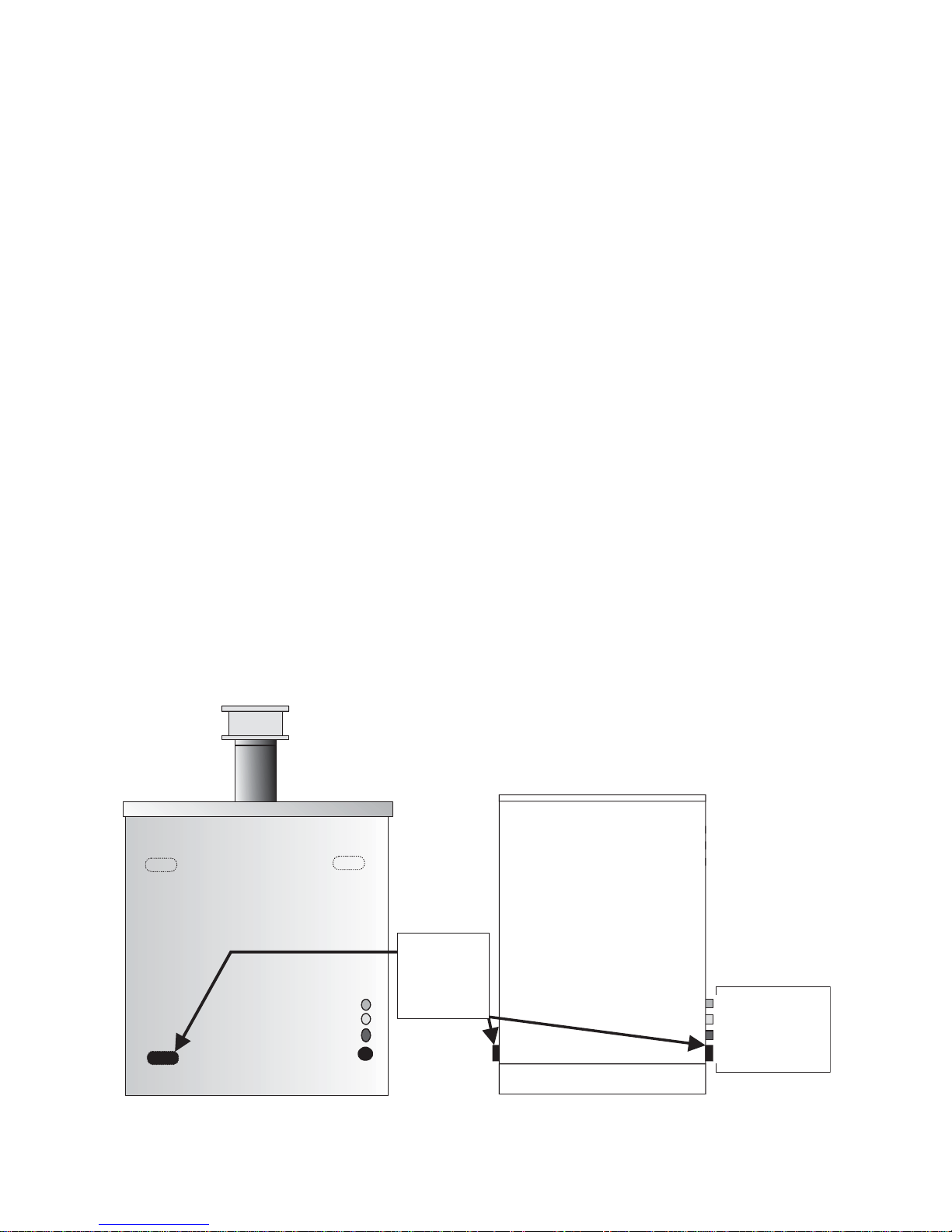
Heating
Return
option
Left or Right
Pipes routed out through rear of External Pipes routed out through rear of Internal
Heating Return
Heating Flow
Cold Mains
Discharge Pipe
Heating Return
Heating Flow
Cold Mains
Discharge Pipe
REGULATIONS
The installation of oil fired boilers should comply with the following standards and codes of
practice.
- BS5449 Forced circulation hot water heating systems for domestic use
- BS5410-Part1 Oil installations up to 45kw.
- BS7593 Water treatment of hot water central heating systems.
- BS7671 Electrical Regulations.
- BS7074 Code of practice for sealed systems
- Building Regulations Part L1 and J 2002 England and Wales, Part F Scottish Regulations
and Technical Booklet L Northern Ireland.
- OFTEC Codes of Practice Published or Recommended.
After installing the system, it needs to be flushed with a cleanser like Fernox Heavy Duty
Restore, for fast -acting removal of lime scale , black sludge (magnetite) and other deposits
from the boiler and the central heating system. Then add a Fernox protector to give long
term protection of the central heating system against internal corrosion and lime scale
formation.
WATER CONNECTIONS
The boiler is supplied with one flow and two return connections. Diagrams below show pipe
configurations.
7
BOILER LOCATION
Sound levels should be discussed with the householder, as some people may be sensitive
to low noise levels in a small room, as it may appear more annoying than in a larger room.
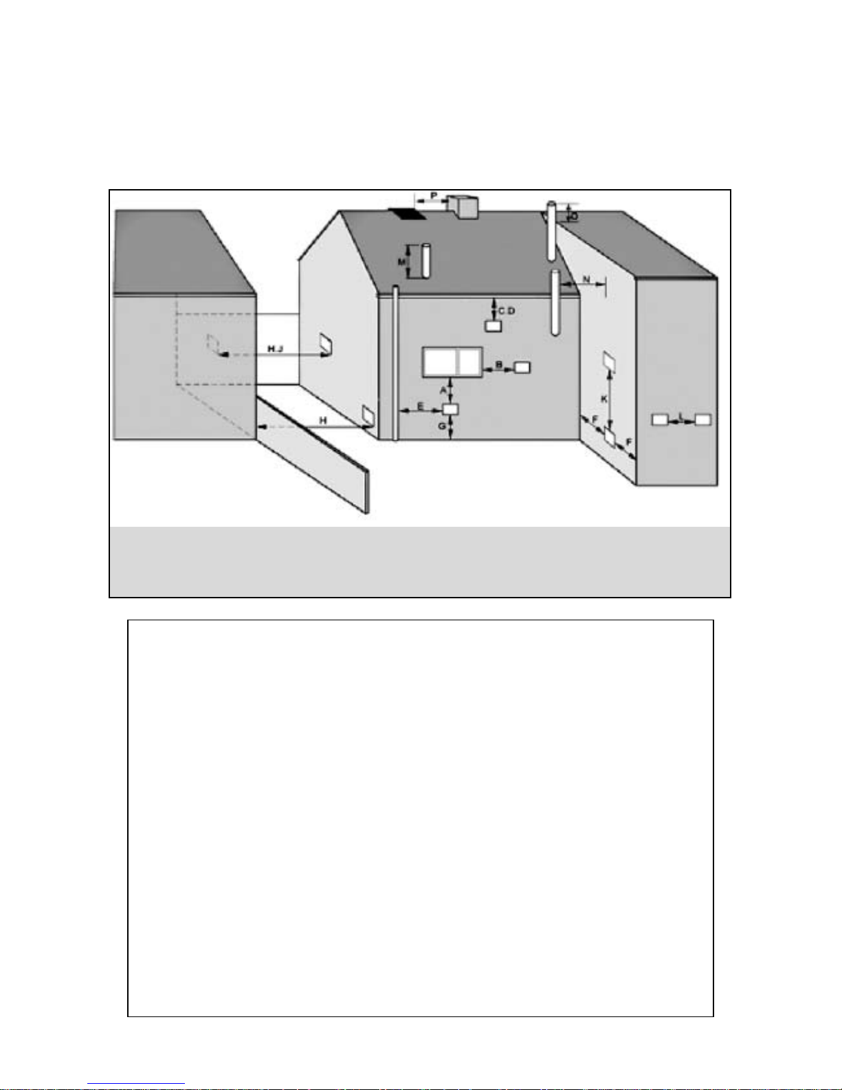
Please Note installation should take into account of flue position (see diagram).
RECOMMENDED FLUE POSITION
8
RefMin. Position mm
A Directly below an opening, air brick, opening window etc. 600
B Horizontally to an opening , air brick, opening window etc. 600
C Below a gutter, eaves or balcony with protection. 75
D Below a gutter or a balcony without protection. 600
EFrom vertical sanitary pipework. 600
FFrom an internal or external corner. 600
G Above ground or balcony level. 600
HFrom a surface or a boundary facing the terminal. 600
JFrom a terminal facing the terminal. 1200
KVertically from a terminal on the same wall. 1500
L Horizontally from a terminal on the same wall. 750
M Above the highest point of an intersection with the roof. 600
NFrom a vertical structure on the side of the terminal. 750
O Above a vertical structure less than 750mm. 600
PFrom a ridge terminal to a vertical structure on the roof. 1500
Please Note where the terminal is within 1 metre of any plastic material, such material
should be protected from the effects of the combustion products of the fuel.
IMPORTANT 35 SECOND CLASS D GAS OIL MUST NOT BE USED FOR BALANCED FLUES.
INSTALLATION
SERVICE REQUIREMENTS
The boilers are serviced though an access panel at the front. A service access space of
least 700mm should be made available at the front of the boiler.
THE HEARTH
The temperature of the surface below the boiler is less than 85˚C. If the floor under the
boiler is of combustible material, then protection such as steel should be fitted between
the boiler and the floor.
Consideration should be given to the weight of the filled boiler, the floor must provide
adequate support. Please consult the building regulations for safe floor loadings.
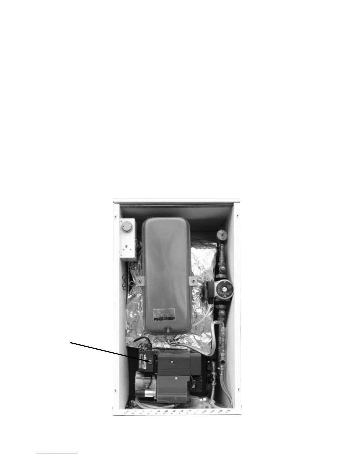
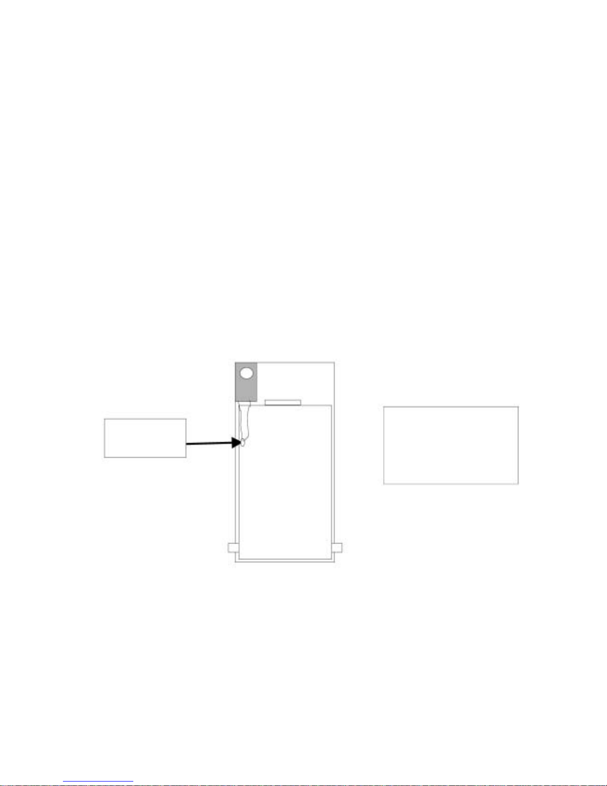
CONTROL PANEL
The boiler control panel is factory fitted prior to despatch. The phials of the Control and
High Limit Thermostat are inserted into the horizontal pocket situated on the left hand side
of the boiler heat exchanger.
9
DIAGRAM OF
PHIAL POSITIONS
ON BOILER HEAT
EXCHANGER
ELECTRICAL ENTRY
The electrical supply to the boiler must be 230 volts, 50 Hz, fused at 5A. Connection of the
appliance and any system controls, to the mains supply, must be a common isolator and
must be fused at 5A maximum.
This must be fixed wired to a double pole isolating switch, that has a maximum contact
separation of 2mm in both poles. The Isolator should be clearly marked showing its
purpose, and preferably positioned close to the boiler.
Control & High
Limit Thermostat

PREFORMED PIPE WORK
- 1 Of 22 mm section label Heating Flow
- 1 Of 22 mm section label Heat Return
- 1 Of 15 mm section label Cold Mains
- 1 Of 15 mm section label Over Flow
Preformed pipes, on the Internal system exit on the right hand side of the boiler. from
the front view of the boiler.
The preformed pipe on the External combi exits at the rear of the casing.
For diagrams on pipe layout go page 7.
The heating return pipe (22mm) can be connected to either the left or right hand
side with the tapping at the bottom rear of the boiler. The unused tapping must be
blanked off.
These tappings are 1” B.S.P.
SEALED SYSTEM
This boiler operates on a sealed system. A pressure relief valve operating at 3 bar is
fitted.
The over flow pipe must terminate in compliance with current building regulations.
This boiler is supplied with a 12 litre expansion vessel. It is the installers responsibility to
ensure adequate provision is made for expansion within the heating system and to
install extra capacity if required. Damage to components caused by over expansion,
may not be covered by warranty.
Unsuitable pipework and fittings and factors such as sediment or residue left in the
system, may cause damage to your boiler and its components and may not be
covered by warranty.
PLA STIC PIPE
PLEASE NOTE: When using plastic pipe on heating system, a minium of 2 metres of
copper pipe must be used off the boiler, before connecting to plastic pipe.
PLASTIC PIPE MUST NOT IN ANY CIRCUMSTANCES BE CONNECTED DIRECTLY TO THE BOILER
10
 Loading...