

EURO ESINF600B, ESINF90B Use And Care Manual
ESINF600B
ESINF90B
COD. 04086IE - 23.06.2016 REV. 00

Dear Customer
Thank you for purchasing a Eurostyle Cooktop.
Before we continue telling you about this cooktop, we cordially invite you to become part
of the Eurostyle family by subscribing to ongoing information and invitations.
You will find that the clean lines and modern look of your Eurostyle Cooktop blends
perfectly with your kitchen décor. It is easy to use and performs to a high standard.
There are models to complement your new Eurostyle Cooktop.
Of course we make every effort to ensure that our products meet all your requirements,
and our Customer Relations department is at your disposal, to answer your questions and
to listen to all your suggestions (see back cover of manual).
Please complete the warranty section of this manual and keep your receipt as proof of
purchase. Retain all documents relating to the purchase of this products.
Eurostyle is committed to providing increasingly efficient products that are easy to use,
respect the environment and are attractive and reliable.
Eurostyle
We ask that you carefully read the instructions within this booklet to enable you to abtain quality
results from the outset.
The appliance must be installed only by an authorised person in compliance with the instructions
provided. The manufacturer declines all responsability for improper installation which may harm
persons and animals and damage property.
The appliance must be used for the purpose for which it was expressly designed. Any other use
(eg heating rooms) is considered to be improper and consequently dangerous. The manufacturer
declines all responsability for damage resulting from improper and irresponsible use.
The manufacturer shall not be held responsible for any inaccuracies in this handbook due to
printing or transcription errors. The designs in the figures are purely indicative.
The manufacturer also reserves the right to make any modifications to the products as may be
considered necessary, useful or in the interests of the user, without jeopardizing the main
functional and safety features on the products themselves.
If your cooktop requires service, please contact your local customer service centre or your
nearest Eurostyle agent listed at the back of this booklet.

90 cm
The appliance has 2/4 cooking areas with different sizes and different power levels. The heating
elements are of the magnetic induction type, which come on after selecting the heating element,
and the heat can be regulated using the controls on the front panel, from a minimum of 1 to a
maximum of 9 (depending on the models). There is also a fast boiling function (booster) indicated
by the letter P on the display.
The cooking areas have concentric discs with the following diameters.
COOKING AREA
TYPE: PCZ VTCI
77 cm
30 cm
Model: ESINF600B
Model: ESINF90B
60 cm
3
60 cm
booster
1 Induction element Ø 210 mm 3000 W
2 Induction element Ø 145 mm 1800 W
3 Touch control
4 Induction element Ø 180 mm 2200 W
5 Induction element Ø 280 mm 3700 W
6 Induction element Ø 270 x 180 mm 2500 W
7 Induction element Ø 235 x 190 mm 2200 W

Guide to Using the Instructions Booklet
Safety instructions
Before first use, you should carefully read
the installation and connection instructions.
For your safety, installation should be
carried out by an authorised technician
and should comply with existing installation standards. Likewise, any internal work
on the hob should only be done by autho-
rized technical staff, including the change
of the flexible supply cable of the appliance.
Safety warnings:
This appliance is not designed to
work with an external timer (not built
into the appliance) or a separate remote control system.
Do not steam clean this device.
The device and its accessible
parts may heat up during operation.
Avoid touching the heating elements.
Children must stay away from the stovetop unless they are permanently
supervised.
The appliance is not intended for
use by persons (including children)
with reduced physical, sensory or mental capabilities, or lack of experience
and knowledge, unless they have been
given supervision or instruction concerning use of the appliance by a person responsible for their safety. User
cleaning and maintenance may not be
done by unsupervised children.
Children should be supervised to
ensure that they do not play with the
appliance.
Danger of Fire: Do not store items
on the cooking surface.
CAUTION: The cooking process
has to be supervised. A short term cooking process has to be supervised continuously.
Precaution. It is dangerous to cook
with fat or oil without being present, as
these may catch fire. Never try to extinguish a fire with water! in this event disconnect the device and cover the flames
with a lid, a plate or a fire blanket.
Do not store any object on the
cooking areas of the stovetop. Prevent
a possible fire hazard.
Do not place metal objects, such as
knives, forks, spoons or lids on the surface of the hob, as they may get very hot.
The induction generator complies
with all current European standards.
Nonetheless, we recommend that people with heart devices, with such as
artificial pacemakers, consult with their
doctor or, if in doubt, refrain from using
the induction zones.
It is advisable not to use the
induction hob during the pyrolitic cleaning function in the case of the pyrolitic
In case o f h o tplate g l a ss
breakage:
●shut immediately off all burners
and any electrical heating element
and isolate the appliance from the
power supply;
●do not touch the appliance surface;
●do not use the appliance.
4
ovens, due to the high temperature reached by this appliance.
When finished, turn off the cooking zone by using the touch controls.
Otherwise an undesired operation
could occur if a pan is accidentally placed on the cooking zone during the
next three minutes. Avoid possible
accidents!
Do not attempt to change the technical characteristics of the product
because it can be dangerous.
If you should not to use this
appliance any more (or replace an old
model), before disposing of it, make it
inoperative in conformity with current
law on the protection of health and the
prevention of environmental pollution
by making its dangerous parts harmless, especially for children who might
play on an abandoned appliance.
Do not touch the appliance with
wet or damp hands or feet.
Do not use the appliance barefoot.
The manufacturer will not be liable
for any damage resulting from improper, incorrect or unreasonable use.
During, and immediately after operation, some parts of the cooktop are
very hot: avoid touching them.
Connecting the electricity
The electric connection is made via an
omnipolar switch or plug where accessible,
which is suitable for the intensity to be tolerated and which has a minimum gap of 3
mm between its contacts, which will ensure
disconnection in case of emergency or
when cleaning the hob.
In case of failure or cut in the cable, please
move away from the cable and do not
touch it. Moreover the device must be
unplugged and not switched on. Call the
nearest authorized service center to fix the
problem. The input cable should not be in
contact either with the body of the hob or
with the body of the oven, if the oven is installed in the same unit.
When using the hob for the first
time, please take care not to have
powerful halogen lights, like those of a
hood, shining over the sensor button
area of the hob. These lights may interfere with the starting of the system.
The electrical connection must be
properly grounded, following current
regulations, otherwise the stovetop
may malfunction.
Unusually high power surges can
damage the control system (like with
any electrical appliance).
5
Ensure the appliance is installed by
an authorised person in accordance
with AS/NZS 3000 wiring rules.
INSTALLATION AND SETUP SHOULD
BE CARRIED OUT BY AN AUTHORISED
TECHNICIAN IN LINE WITH CURRENT
INSTALLATION STANDARDS AND THE
MANUFACTURER'S INSTRUCTIONS.
Positioning the hob
To install these models, an opening with
the dimensions shown in figure 1 will be
cut into the unit’s worktop.
The fastening system for the top is designed for furniture thicknesses of 20, 30 and
40 mm.
The minimum distance between the surface supporting the cooking pans and the
lower part of the kitchen unit or the hood
located above the hob should be 650 mm.
If the hood’s installation instructions
recommend that the gap is greater than
this, you should follow this advice.
The unit where the hob and oven will be
located will be suitably fixed.
INSTALLATION WITH FAN OVEN
UNDER THE HOB
The oven should be installed according to
the corresponding manual.
An opening of 20 mm should be made in
the back part of the cabinet in order to
allow cold air to enter (see figure 1).
When hobs are handled before
being installed, care should be taken in
case there is any protruding part or
sharp edge which could cause injury.
When installing units or appliances above the hob, the hob should be
protected by a board so that the glass
cannot be damaged by accidental
blows or heavy weights.
The glues used in manufacturing
the kitchen unit and in the adhesive on
the decorative laminate of the worktop
surface should be made to tolerate temperatures of up to 100 ºC.
Manufacturer assumes no responsibility for any malfunction or
damage caused by faulty installation.
PLEASE REMEMBER THAT THE GUARANTEE DOES NOT COVER THE
GLASS IF IT SUFFERS A VIOLENT
BLOW OR IF IT IS USED IMPROPERLY.
Fastening the hob
When the gap has been properly sized, the
sealing washer should be put on the lower
face of the glass. Silicone should not be
applied between the glass and the unit
worktop because if it becomes necessary to remove the hob from its position,
the glass could break when trying to
detach it.
To secure the hob to the cabinet, four brackets should be fastened to the existing holes
on the bottom part of the casing (two in the
front and two in the back). There are two
possibilities of where the brackets may be
placed, just as is shown in figure 3.
Depending on the thickness of the cabinet, it
may be necessary to use the self tapping
screws that are provided as compliments for
securing; insert them in the circular holes of
the bracket. The thread of this hole will be
made when the screw is inserted inside of it.
The thread should be made before fastening the bracket to the hob.
Installation
6
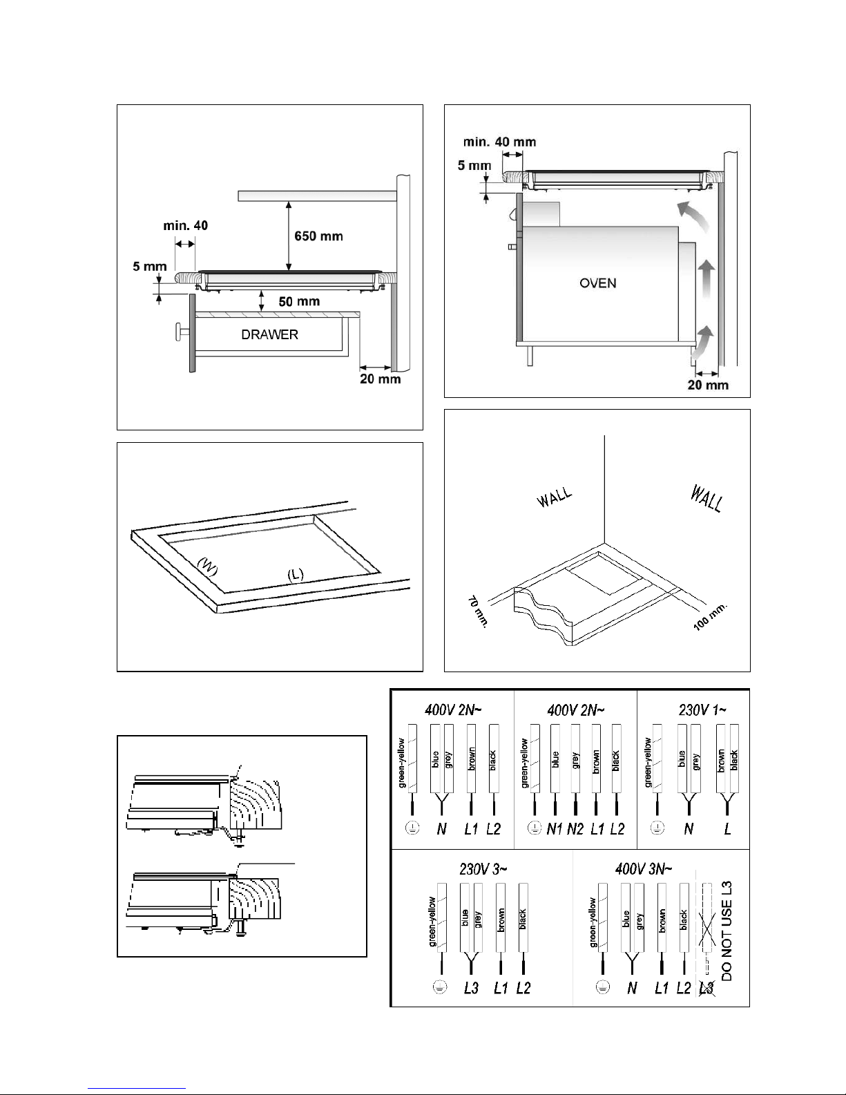
fig. 2
Minimum ventilation
distances
Minimum ventilation
distances
Fitting holes
Minimum distance
to wall
7
Sealing washer
Sealing washer
fig. 3
fig. 1
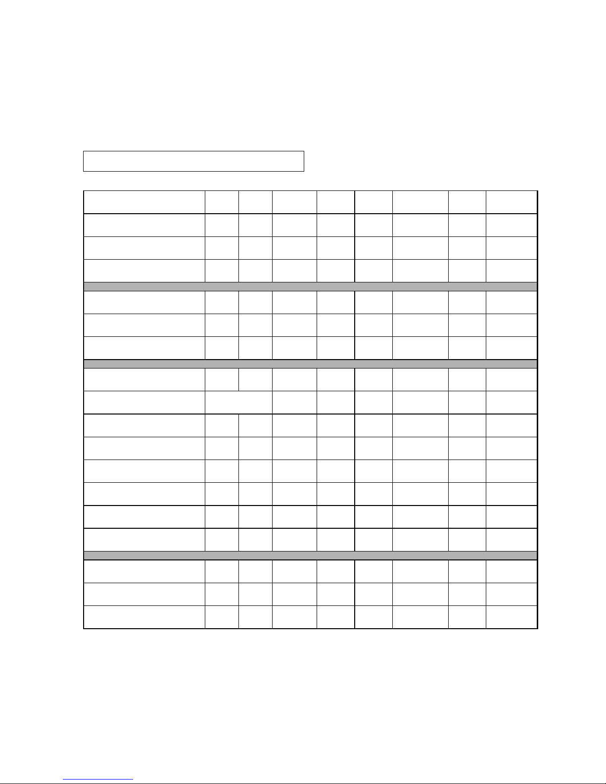
Technical details
Class 3 hob.
Dimensions and characteristics
ESINF600B ESINF90B
Height (mm) 55 55 55 60 60
Lenght (mm) 505 505 505 505 505
Width (mm) 300 580 580 770 900
Width (mm) (W) 498 480 480 480 480
Lenght (mm) (L) 270 560 560 750 860
Depth (mm) 105 105 105 105 105
W MJ/h Ø
booster
Induction hotplate 1800 6.5 145 1 2 1 1 1
Induction hotplate 2200 8.0 180 1 2
Induction hotplate 3000 10.8 210 1 1 1 1
Induction hotplate 3700 13.3 280 1
Induction hotplate 2500 9.0 270x180 2
Induction hotplate 2200 9.0 235x190 2
Nominal Power (W) for 230V 4800 8800 7000 9200 7400
Supply voltage (V) 220/240 220/240 220/240 220/240 220/240
Frequency (HZ) 50/60 50/60 50/60 50/60 50/60
8

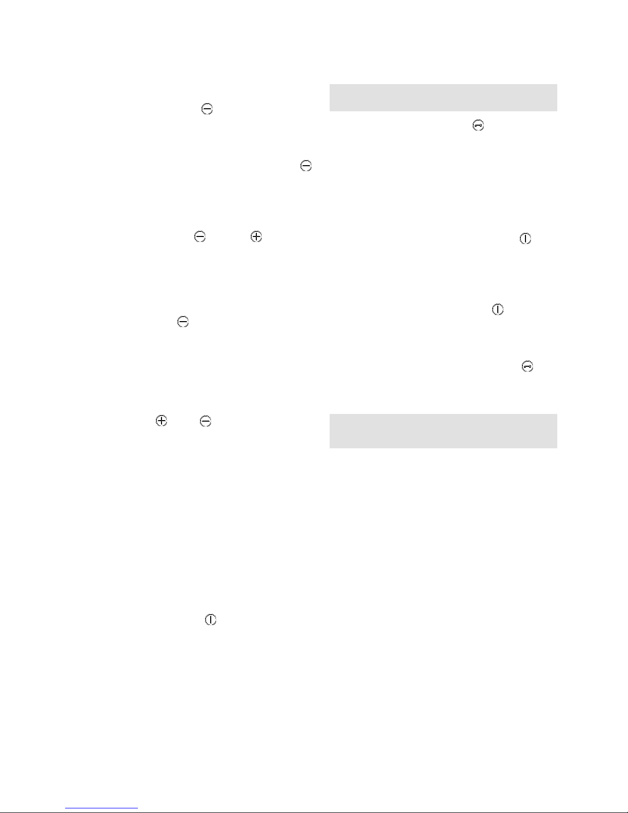
Touch control user
instructions
CONTROL PANEL ELEMENTS
N.B.: * Only visible when in operation.
The sensors marked on the control panel
are used for control purposes.
There is no need to exert pressure on the
glass - you enable the function you require simply by touching the sensor with your
finger.
Each action is confirmed by a beep.
SWITCHING THE APPLIANCE ON
1) Touch the on sensor (1) for at least
one second. The Touch Control will activate, you will hear a beep and the indicators will turn on. If any of the cooking
areas is hot, the corresponding indicator
will alternate between showing a H and
a 0.
The following action must be carried out
within 10 seconds or the touch control will
automatically switch off.
When the touch control is activated, it can
be disconnected at any time by touching
the sensor (1), even if it has been
blocked (blocking function activated). The
sensor (1) always takes priority for disconnecting the touch control.
SWITCHING THE HOTPLATES ON
The hotplates will be found deactivated,
with their respective power indicators (3)
at 0, until a power level is selected. If all
the hotplates are set at 0, you have 10
seconds to activate any of them, otherwise
the touch control will automatically turn off.
Use the sensors and (4/5) to select
a power level. If you touch the sensor
(5), the plate will switch to level 1 and,
Use and Maintenance
1
On/off sensor.
2
Hotplate indicators.
3
Power and/or residual heat indicators.
4
Reduce power sensor (less).
5
Increase power sensor (more).
6
Timer/Clock indicator.
7
Indicator of selected time (clock).
8
Locking sensor (for the rest of the
sensors, eccept on/off).
9
Indicator light of the induction
element with timer.
10
Pilot light for activated locking.
11
Time reduction sensor on clock (less).
12
Time increasing sensor on clock (more).
13
Countdown indicator (blinks each second).
30 cm.
9
for each additional stroke, it will go up one
level until reaching the maximum value of
P. Using the sensor (4), you can redu-
ce the power level.
For a fast powering up at maximum power:
with the plate at 0, touch the sensor
(4) once. The plate will directly activate at
level 9.
By continuing to press down on any of
these two sensors (4) or (5), they
will repeat the action every half a second,
without needing to press consecutively.
SWITCHING THE HOTPLATES OFF
With the sensor (4), lower the power to
level 0.
The hotplate will automatically power off.
For a fast power up: no matter what the
power level, by simultaneously pressing
the sensors and (5/4), the plate will
immediately power off.
By powering off a hotplate, an H will be
shown on the power indicator, if the glass
surface is at a high temperature, indicating
that there a risk of burning. When the temperature has fallen, the indicator will power
off if the top is disconnected or, if it is turned on, it will indicate a 0.
POWERING OFF THE DEVICE
At any time, you can disconnect the top by
pressing the sensor (1). When doing
this, an acoustic signal is heard and the
power indicators (3) will turn off, except if
there is a residual H heat indicator active
due to the plate temperature.
Locking the sensors
Using the locking sensor (8), you can
block all the sensors on the touch control
panel. This will make it possible to avoid
undesired accidental operations occurring
or children being able to manipulate the
control.
Bear in mind that with the touch control
powered up, the on/off sensor (1)
makes it possible to turn it off even if the
locking is activated (pilot 10 on). On the
other hand, if the touch control is turned
on, the locking function does not allow for
activating the on/off sensor (1). You
should first deactivate blocking.
To activate or deactivate the function,
simply keep pressing the sensor (8)
for about 1 second. When the function is
active, the pilot light (10) turns on.
Detecting pans
(induction hotplates)
The induction cooking plates incorporate a
container detector. This is to avoid the
plate operating without having a pan on
top or when the container is unsuitable,
e.g., if made of aluminium or another nonmetallic material.
The power indicator blinks if, with the plate
turned on, no pan or an inappropriate pan
is detected.
If the pans are removed from the hotplate
while operating, this will automatically cut
off the power supply and the power indicator will blinks. When putting the pan on the
cooking hotplate again, the power supply
restarts at the power level that was selected.
The time for detecting the pan is immedia-
10

tely. If within three minutes go by without
having placed a pan on the hotplate or if
an inappropriate one is placed there, the
cooking plate deactivates.
After use, switch off the hob element by its
control and do not rely on the pan detector.
Power supplied according to
the power level selected
Bear in mind that induction areas adjust the
amount of power supplied according to the
size and type (material) of pan placed on
them. A smaller pan will receive less power
than a larger one. Thus, depending on the
pan being used, the power supplied may
vary from the values shown in Table 1.
Power function
This function makes it possible to give a
plate "extra" power, higher than the nominal. This power level depends on the size
of the plate, being possible to reach the
maximum allowed by the generator.
POWER FUNCTION CONNECTION
1 Activate the plate corresponding to
power level 9.
2 From power level 9, press the sensor
and the symbol P will be displayed
on the indicator.
The Power function lasts for a maximum of
10 minutes. After this time, the power level
will automatically set to level 9.
POWER FUNCTION DISCONNECTION
The Power function can be disconnected
by pressing the sensor associated with
the hotplate in question.
The function can also be disconnected
automatically if the temperature in the cooking area is very high.
Fondue function
This function is especially designed for
melting butter, cheese, chocolate, etc. It is
a lower power level than level 1.
To access this function:
1 Activate the plate you wish to use at
power level 1.
2 Press the sensor (4) and the indica-
tor will show the symbol .
To deactivate the function, simply touch
the sensors (4) or (5) and the indicator will display, respectively, a lower
power level 0 or higher 1.
Safety disconnection
MAXIMUM FUNCTION TIME
In the event of forgetting to turn off the plate,
it will automatically power off after a given
time after the last time the plate was activated. (See Table 2).
11

When the "safety disconnecting" has occurred, in the corresponding plate's power
indicator the residual heat H indicator will
be displayed, if the glass temperature is
high enough.
SAFETY WHEN SENSORS ARE COVERED
The Touch Control incorporates a function
that detects when any object (pan, cloth or
certain liquids) are covering the panel sensors for more than 10 seconds. This is to
avoid the object activating or deactivating
any of the plates without you realizing.
When the Touch Control detects an object
covering the sensors, it starts to bleep until
the object covering the control panel is
removed. If the Touch Control was turned
on, it is automatically disconnected for
safety reasons.
If after a few minutes the object covering
the sensors is not removed, the bleeping
will stop.
Take into account that this safety
function is activated even though the
Touch Control is turned off!
Do not leave any objects down on
the Touch Control!
Clock
The top is fitted with a clock that can be
used for two different functions: as a plate
timer or as a countdown chronometer.
The clock as a countdown timer
With this function, you can set a time after
which a sound signal will be heard.
To activate this function, proceed as
follows:
1 With the Touch Control powered on and
no plate with the timer activated, touch
one of the sensors (11) or (12)
corresponding to the clock.
2 Power on the indicator (7), displaying
00.
3 Touch the sensors (11) or (12)
again to set the required time. After a
few seconds, the decimal point on clock
will start to blink (13), indicating that the
countdown has begun.
Be careful not to touch different sensors
other than (11) or (12) since, by
doing so, a plate may cease timing instead
of programming the chronometer.
Once the countdown has reached zero, a
series of bleeps will be heard. These can
be cancelled by touching any of the sensors (11) or (12) associated with
the clock.
Table 2
8
8
5
4
4
3
3
2
2
1
10 minutes
1
2
3
4
5
6
7
8
9
P
Power
selected
MAXIMUM
OPERATION TIME
(in hours)
12
 Loading...