

EURO EPZ4GWH, EPZ4GSFD, EPZ3WGSX, EPZ4GSX, EPZ3WGCTS Use, Installation And Maintenance Instructions
...Page 1
MODELS:
EPZ4GWH - EPZ4GSX
EPZ4GSFD - EPZ3WGSX
EPZ3WGCTS - EPZ4EEWH
EPZ4EESX
We ask that you carefully read the instructions within this booklet to enable you to abtain quality results from the outset.
The appliance must be installed only by an authorised person in compliance with the instructions provided. The manufacturer
declines all responsability for improper installation which may harm persons and animals and damage property.
The appliance must be used for the purpose for which it was expressly designed. Any other use (eg heating rooms) is considered to
be improper and consequently dangerous. The manufacturer declines all responsability for damage resulting from improper and
irresponsible use.
The manufacturer shall not be held responsible for any inaccuracies in this handbook due to printing or transcription errors. The
designs in the figures are purely indicative.
The manufacturer also reserves the right to make any modifications to the products as may be considered necessary, useful or in the
interests of the user, without jeopardizing the main functional and safety features on the products themselves.
If your cooktop requires service, please contact your local customer service centre or your nearest Eurostyle agent listed at the back
of this booklet.
COD. 01099HM - 11.05.2012
Dear Customer
Thank you for purchasing a Eurostyle Cooktop.
Before we continue telling you about this cooktop, we cordially invite you to become part of the Eurostyle family by
subscribing to ongoing information and invitations.
You will find that the clean lines and modern look of your Eurostyle Cooktop blends perfectly with your kitchen
décor. It is easy to use and performs to a high standard.
There are models to complement your new Eurostyle Cooktop.
Of course we make every effort to ensure that our products meet all your requirements, and our Customer
Relations department is at your disposal, to answer your questions and to listen to all your suggestions (see back
cover of manual).
Please complete the warranty section of this manual and keep your receipt as proof of purchase. Retain all
documents relating to the purchase of this products.
Eurostyle is committed to providing increasingly efficient products that are easy to use, respect the environment
and are attractive and reliable.
Eurostyle
USE, INSTALLATION AND MAINTENANCE
INSTRUCTIONS FOR BUILT-IN HOT PLATES
Page 2
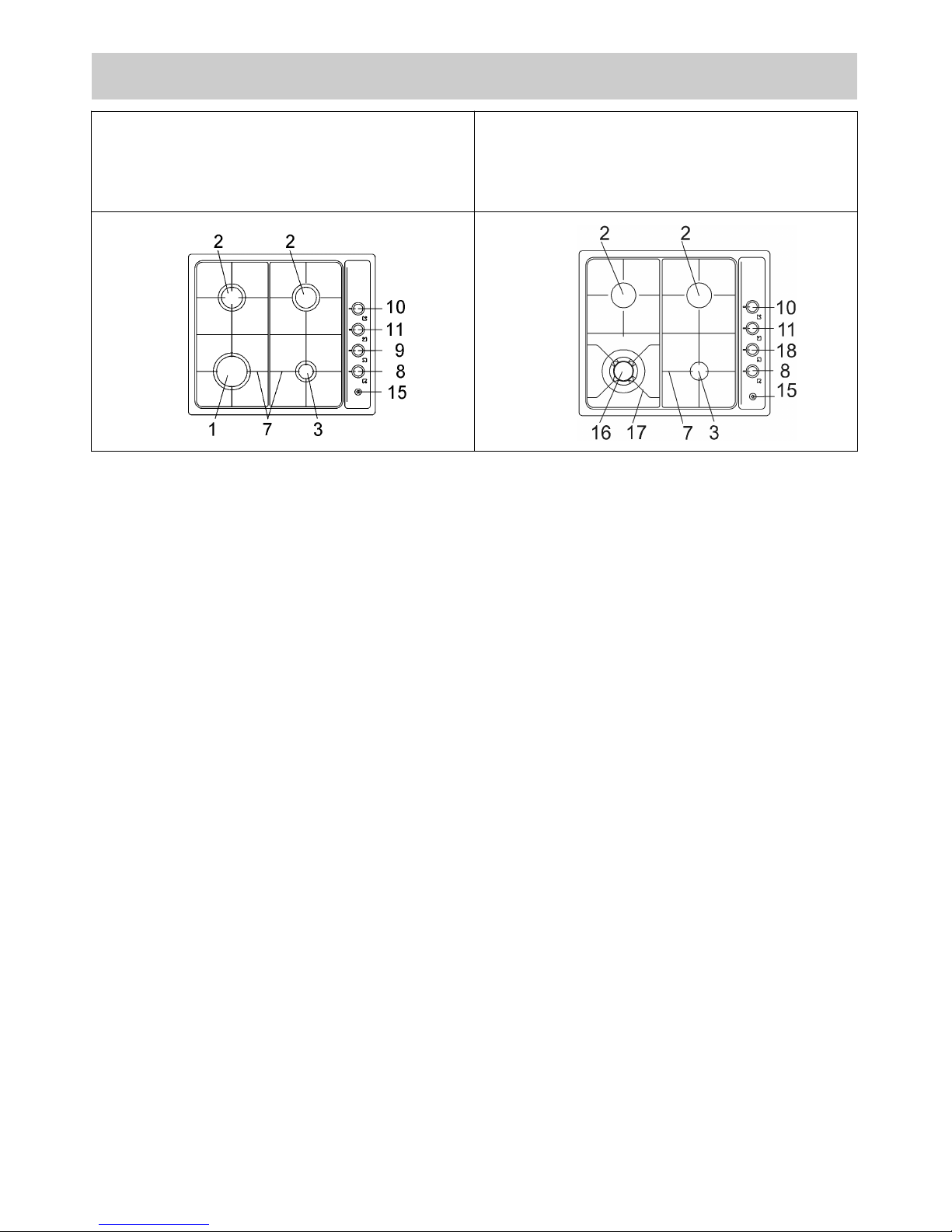
2
Natural U-LPG
1 Rapid gas burner 12.0 MJ 10.4 MJ
2 Semi-rapid gas burner 7.1 MJ 6.2 MJ
3 Auxiliary gas burner 4.1 MJ 3.5 MJ
7 Trivet 2 burner
8 Burner 3 control knob
9 Burner 1 control knob
10 Burner 2 control knob (right)
11 Burner 2 control knob (left)
15 Electric ignition button
16 Ultra rapid gas burner/Wok 14.5 MJ 11.4 MJ
17 Trivet for ultra rapid burner
18 Burner 16 control knob
Attention: this appliance has been manufactured for domestic use only and it employment by
private person.
DESCRIPTION OF THE HOT PLATES
MODELS:
EPZ3WGSX - EPZ3WGCTS
MODELS:
EPZ4GWH - EPZ4GSX
EPZ4GSFD
Page 3

1) BURNERS
A diagram is screen-printed above each knob on
the front panel. This diagram indicates to which
burner the knob in question corresponds. After
having opened the gas mains or gas bottle tap, light
the burners as described below:
- manual ignition
Push and turn the knob corresponding to the
required burner in an anticlockwise direction until it
reaches the full on position (large flame fig. 1), then
place a lighted match near the burner.
- Automatic electrical ignition
Push and turn the knob corresponding to the
required burner in an anticlockwise direction until it
reaches the full on position (large flame fig. 1), then
depress the knob.
- Lighting burners equipped with flame failure
device
The knobs of burners equipped with flame failure
device must be turned in an anticlockwise direction
until they reach the full on position (large flame
fig. 1) and come to a stop. Now depress the knob in
qu estio n an d re peat the previously indicated
operations.
Keep the knob depressed for about 10 seconds
once the burner has ignited.
Note: you are advised not to try and light a burner if
the flame divider (Burner Cap) is not correctly
placed.
HOW TO USE THE BURNERS
Bear in mind the following indications in order to
achieve maximum efficiency with the least possible
gas consumption:
- use adequate pans for each burner (consult the
following table and fig. 2).
- When the pan comes to the boil, set the knob to
the reduced rate position (small flame fig. 1).
- Always place a lid on the pans.
Burners Power ratings Pan Ø in cm
Natural U-LPG
Ultra rapid
or Wok 14.5 MJ 11.4 MJ 22 - 24
Rapid 12.0 MJ 10.4 MJ 20 - 22
Semi-rapid 7.1 MJ 6.2 MJ 16 - 18
Auxiliary 4.1 MJ 3.5 MJ 10 - 14
WARNINGS:
- burners with flame failure device may only be
ignited when the relative knob has been set to
the Full on position (large flame fig. 1).
- Matches can be used to ignite the burners in a
blackout.
- Never leave the appliance unattended when the
burners are being used. Make sure there are no
children in the near vicinity. Particularly make
sure th at th e pan handles are correctly
posit ion ed and keep a che ck on foods
requiring oil and grease to cook since these
products can easily catch fire.
- Never use aerosols in the vicinity of this
appliance while it is in operation.
- If the built-in hot plate has a lid, any spilt food
should be immediately removed from this
before it is opened. If the appliance has a glass
lid, this could shatter when the hot plate
becomes hot. Always switch off all the burners
before closing the lid.
- This appliance is not to be installed in marine
craft. Where this appliance is installed in a
caravan, it shall not be used as a space heater.
- Do not store or use flammable liquids or items
in the vicinity of the hotplate.
- Do not modify this appliance.
3
USE
FIG. 1 FIG. 2
In the event of the Burner flames being accidentally
extinguished, turn off the burner control and do not
attempt to re-ignite the burner for a least 1 minute.
Page 4
4
USE
Notes:
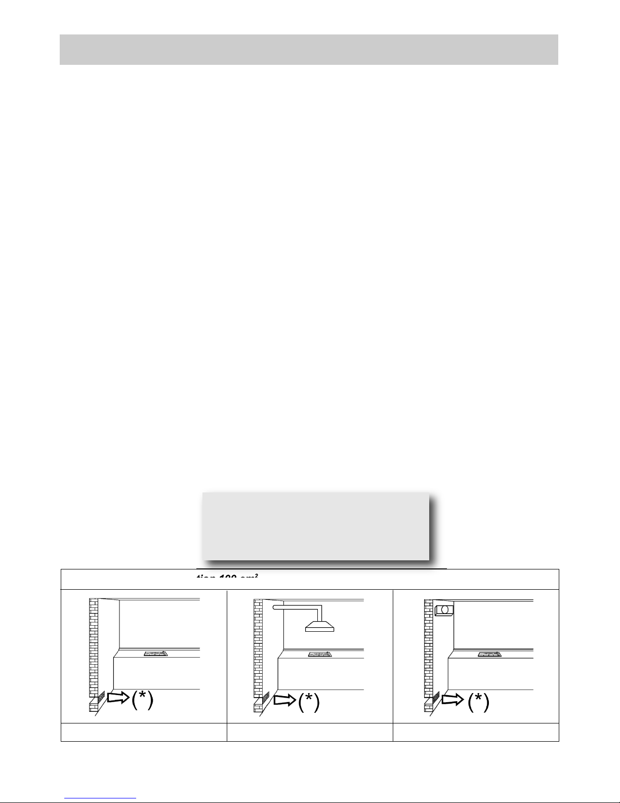
use of a gas cooking appliance produces heat and moisture in the room in which it is installed. The
room must therefore be well ventilated by keeping the natural air vents clear (fig. 3) and by
activating the mechanical aeration device (suction hood or electric fan fig. 4 and fig. 5).
Intensive and lengthy use of the appliance may require additional ventilation. This can be achieved
by opening a window or by increasing the power of the mechanical exhausting system if installed.
Star Trivet: use star trivet whenever using a small pot.
Do not attempt to change the technical characteristics of the product because it can be dangerous.
- If you should not to use this appliance any more (or replace an old model), before disposing of it,
make it inoperative in conformity with current law on the protection of health and the prevention of
environmental pollution by making its dangerous parts harmless, especially for children who
might play on an abandoned appliance.
- Do not touch the appliance with wet or damp hands or feet.
- Do not use the appliance barefoot.
- The manufacturer will not be liable for any damage resulting from improper, incorrect or
unreasonable use.
- During, and immediately after operation, some parts of the cook top are very hot: avoid touching
them.
- After using the cook top, make sure that the knob is in the closed position and close the main tap
of the gas supply or gas cylinder.
- If the gas taps are not operating correctly, call the Service Department.
Abnormal Operation:
any of the following are considered to be abnormal operation and may require servicing:
- yellow tipping of the hob burner flame.
- Sooting up of cooking utensils.
- Burners not igniting properly.
- Burners failing to remain alight.
- Burners extinguished by cupboard doors.
- Gas valves which are difficult to turn.
In case the appliance fails to operate correctly, contact the authorised service provider in your area.
FIG. 3 FIG. 4 FIG. 5
(*) Air inlet – minimun section 100 cm
2
Warning:
during operation the work surfaces of the
cooking area become very hot: keep children
away!
Page 5

5
CLEANING
FIG. 6
IMPORTANT:
always disconnect the appliance from the gas
and electricity mains before carrying out any
cleaning operation.
2) HOT PLATE
Periodically wash the hot plate, the enamelled steel
pan support, the enamelled burner caps “C” and the
burner heads “T” (see fig. 6) with lukewarm soapy
water. Following this, all parts should be thoroughly
rinsed and dried. Never wash them while they are
still warm and never use abrasive powders. Do not
allow vinegar, coffee, milk, salted water, lemon or
tomato juice from remaining in contact with the
enamelled surfaces for long periods of time.
WARNINGS:
comply with the following instructions, before
remounting the parts:
- check that burner head slots “T” (fig. 6) have
not become clogged by foreign bodies.
- Check that enamelled burner cap “C” (fig. 6)
have correctly positioned on the burner head.
It must be steady.
- The exact position of the pan support is
established by the rounded corners, which
should be set towards the side edge of the hot
plate.
- Do not force the taps if they are difficult to
open or c lose. Contac t the tech nical
assistance service for repairs.
- Don’t use steam jets for cleaning the cooktop.
CARE & MAINTENANCE
To optimi ze the appe arance and u p keep o f
stainless steel:
1) ALWAYS keep stainless steel out of contact from
acid/acid based solvent (liquid or vapour form).
2) After installation, wipe clean all stainless steel
products with a soft damp cloth to remove any
traces of dirt (e.g. cement dust) or condensation
marks.
In the event where persistent marks appear:
immediately clean affected areas with stainless
steel cleaner, using a clean damp soft cloth.
Ensure surface is rinsed and thoroughly clean of all
marks and stainless steel cleaner.
PREVENTATIVE MAINTENANCE
This co okt op s hould no t re quire ongoi ng
maintenance provided you ensure:
- all spillages are cleaned up as soon as they occur.
- Burners are kept clean.
- Burner ports are free of debris, food or anything
else that may cause an obstruction.
- Electrode and thermocouples are kept clean.
- Burners are re-assembled correctly.
- Do not get water in the area where the injectors
are located.
Note:
continuous use could cause the burners to
change colour due to the high temperature.
Page 6
6
INSTALLATION
TECHNICAL INFORMATION
FOR THE INSTALLER
Thi s appliance s hall be installed only by
authorised personnel and in accordance with
the manufacturer’s installation instructions,
local gas fitting regulations, municipal building
codes, water supply regulations, electrical
wiring regulations, AS 5601/AG 601 – Gas
Inst allat ions and any othe r s tatut ory
regulations.
Ve ntila tion must be in ac corda n ce wi t h
AS 5601/AG 601 - Gas Installation.
In general, the appliance should have adequate
ventilation for complete combustion of gas,
proper flueing and to maintain temperature of
immediate surroundings within safe limits. The
wall and bench surfaces must be capable of
sust ainin g t emper ature s o f 75 °C. A ll
lam inat es, fixi ng adhe sive and sur faci ng
mate rials sho uld b e su itabl e fo r th is
temperature.
3) INSTALLING THE HOT PLATE
Check that the appliance is in a good condition after
having removed the outer packaging and internal
wrappings from around the various loose parts. If in
any doubt, do not use the appliance and contact
qualified personnel.
Never leave the packaging materials (cardboard,
bags, polystyrene foam, staples, etc.) within
children’s reach since they could become
potential sources of danger.
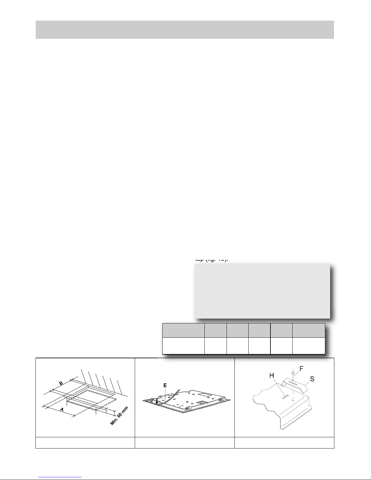
The measurements of the opening made in the top of
the modular cabinet and into which the hot plate will
be installed are indicated in fig.8. Always comply with
the measurements given for the hole into which the
appliance will be recessed (see fig. 8).
Any adjoining wall surface situated within 200 mm
from the edge of any hob burner must be a suitable
non-combustible material for a height of 150 mm for
the entire length of the hob. Any combustible
construction above the hotplate must be at least
600 mm above the construction above the top of
the burner and no construction shall be within 450
mm above the top of the burner. A minimum depth
of 60 mm from the top of the work surface must be
provided for this appliance.
4) FIXING THE COOKTOP
The hot plate has a special seal which prevents
liquid from getting into the cabinet. Strictly comply
with the following instructions in order to correctly
apply this seal:
- detach the seals from their backing, checking that
the transparent protection still adheres to the seal
itself.
- Overturn the hot plate and correctly position seal
“E” (fig. 9) under the edge of the hot plate itself, so
that the outer side of the seal perfectly matches
the outer edge of the hot plate. The ends of the
strips must fit together without overlapping.
- Evenly and securely fix the seal to the hot plate,
pressing into place with the fingers and remove
the strip of protective paper from the seal and set
the plate into the hole made in the cabinet.
- Fix the hob with the proper brackets “S” and fit the
prominent part into the porthole “H” on the bottom;
turn the screw “F” until the bracket “S” stick on the
top (fig. 10).
FIG. 8 FIG. 9
FIG. 10
COMPLY WITH THE DIMENSIONS
Overall Dimensions: 580 x 500 mm
IMPORTANT:
a perf e ct insta llati o n, adju s tment or
transformation of the cook top to use other
gases requires a QUALIFIED INSTALLER: a
fail ure t o follo w this ru le will void t he
warranty.
A B C D E
4F 553 473 63.5 63.5 63.5 min.
Page 7
7
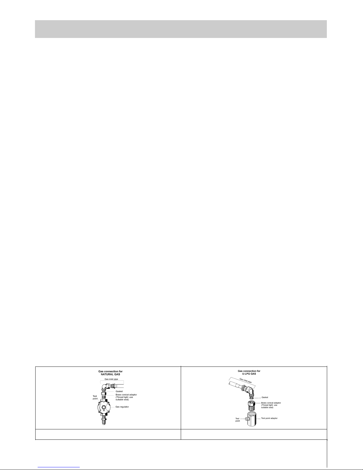
5) GAS CONNECTION
The gas connection is located in the rear and on the
underside of the appliance 100 mm from the right
hand side.
A. The hotplate can be connected with rigid pipe as
specified in AS5601 table 3.1.
B. If installing with a hose assembly, install with a
hose assembly that complies with AS/ANZ 1869
(AGA Approved), 10mm ID, class B or D, no more
than 1.2m long and in accordance with AS5601.
Ensure that the hose does not contact the hot
surfaces of the hotplate, oven, dishwasher or any
other appliance that may be installed underneath or
next to the hotplate. The hose should not be
subje cte d to abrasion , kinking or p ermanent
deformation and should be able to be inspected
along its entire length with the cooktop in the
installed position.
Unions compatible with the hose fittings must be
used and all connections tested for gas leaks.
Natural Gas
Natural Gas installations require the connection of
a gas regulator at the appliance. This regulator is
supplied with the appliance on purchase.
Assemble the regulator (noting the gas flow
direction) and transition pieces (supplied with the
appliance), in accordance with figure 12.
The transition piece on the supply side of the
regulator must be provided by the installer.
Liquified Petroleum Gas
In a LPG installation the gas regulation is made at
the gas cylinder and regulation at the appliance is
not required. To connect supply to the appliance
use transition pieces as shown in figure 12. These
piec es are suppli ed with the a pplia nce on
purchase.
WARNING:
THE BURNER FLAME MUST BE ADJUSTED BY
THE INSTALLER.
FAULTY INSTAL LATION WILL N O T B E
COVERED UNDER WARRANTY.
THE APPLI ANCE IS FACTORY S ET FOR
NATURAL GAS. THE TEST POINT PRESSURE
SHOULD BE ADJUSTED TO 1.00kPa WITH THE
WOK BURNER OPERATING AT MAXIMUM.
INSTALLATION
FIG. 11
FIG. 12
Page 8
6) ELECTRICAL CONNECTION
The appliance is supplied with a 1800 mm long
flexible supply lead.
The point of attachment for this lead is located at
the rear and on the underside of the appliance
380 mm from the right hand side.
The voltage and power consumption are detailed
on the underside of the appliance. Ensure that the
appliance is correctly rated to the supply.
Connect appliance by way of a switched power
point.
THE APPLIANCE MUST BE EARTHED
Ensure that this power point is properly earthed.
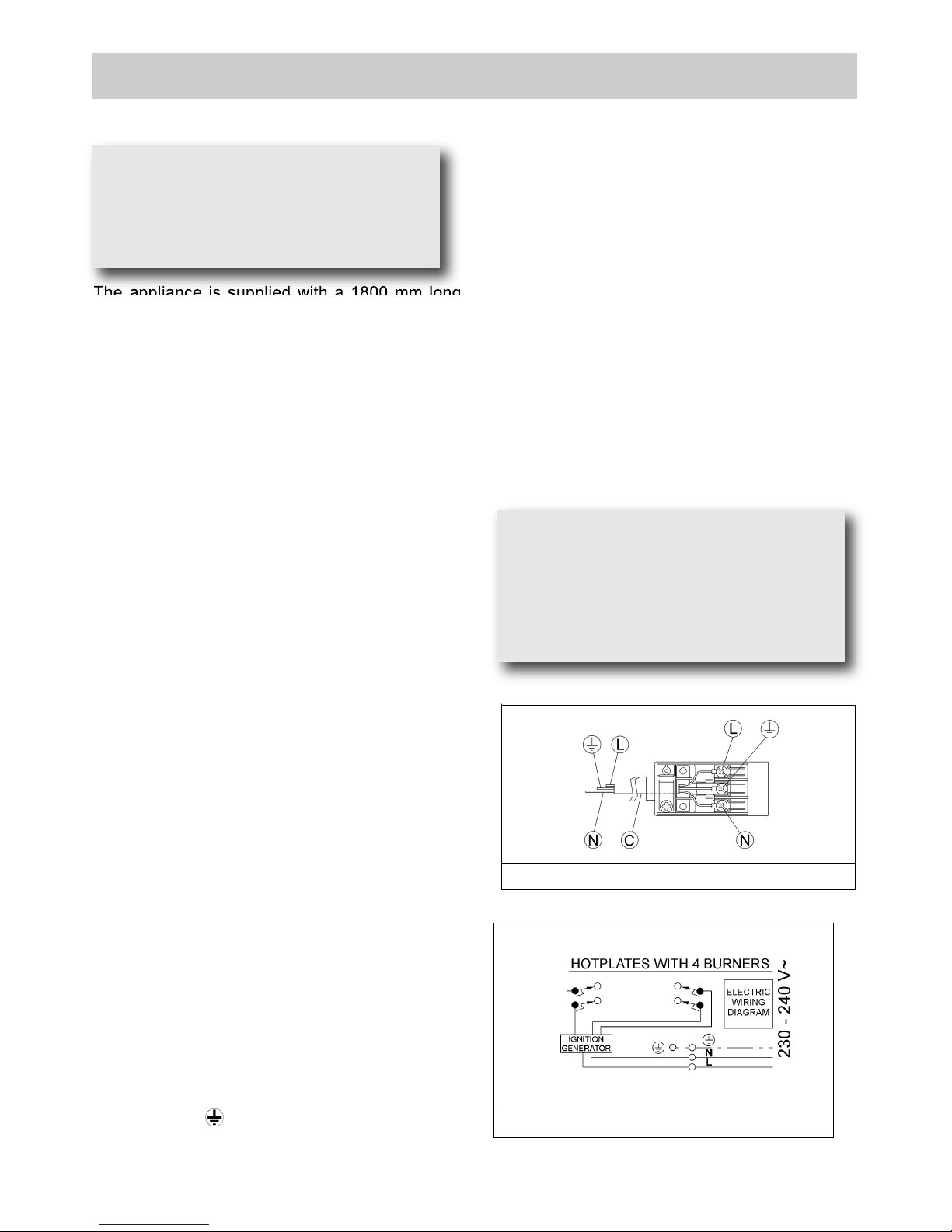
Look a t the conn ectio n wirin g d iagr a ms
(fig. 12/B).
Warning: in order to avoid any hazard, any
electrical work performed on this equipment or
its associated wiring, should only be done by
persons authorised by the supplier or similarly
qualified persons.
The socket outlet for this hotplate shall be
installed near the hotplate and shall be easily
accessible.
The electrical connections of the appliance
must be carried out in compliance with the
provisions and standards in force.
Before connecting the appliance, check that:
- the voltage matches the value shown on the
specification plate and the section of the wires of
the electrical system can support the load, which
is also indicated on the specification plate.
- The electrical capacity of the mains supply and
current sockets suit the maximum power rating of
the appliance (consult the data label applied to the
underside of the hot plate).
- The socket or system has an efficient earth
connection in compliance with the provisions and
standards in force. The manufacturer declines all
responsibility for failing to comply with these
provisions.
When the app liance is con nected to the
electricity main by a socket:
- Fit a standard plug suited to the load indicated on
the data label to the cable.
- Fit the wires following figure n.13, taking care of
respecting the following correspondences:
Letter L (live) = brown wire;
Letter N (neutral) = blue wire;
Earth symbol = green - yellow wire.
- The power supply cable must be positioned so
that no part of i t is a ble t o reach a n
overtemperature of 75 K.
- Never use reductions, adapters of shunts for
connection since these could create false contacts
and lead to dangerous overheating.
When the appliance is connected straight to the
electricity main:
- Install an omnipolar circuit-breaker between the
appliance and the electricity main. This circuitbreaker should be sized according to the load
rating of the appliance and possess a minimum 3
mm gap between its contacts.
- Remem ber that the earth wi re must no t be
interrupted by the circuit-breaker.
-The electrical connection may also be protected by
a high sensitivity differential circuit- breaker.
You are strongly advised to fix the relative yellowgreen earth wire to an efficient earthing system.
Before performing any service on the electrical
part of the appliance, it must absolutely be
disconnected from the electrical network.
INSTALLATION
8
IMPO RTANT: the appli a nce must be
in stalled following the manufacturer's
instructions. The manufacturer will not be
liable for injury to persons or animals or
property damage caused by an incorrect
installation.
If the installation requires modifications to
the home's ele ctr ical system or if the
socket is incompatible with the appliance's
plug , h ave chan ges or repl aceme n ts
performed by profes sio nal ly- qualified
person. In particular, this person must also
make sure that the section of the wires of
the soc k et i s su itabl e fo r th e power
absorbed by the appliance.
FIG. 13
FIG. 12/B
Page 9
9
ADJUSTMENTS
Always disconnect the appliance from the
electricity main before making any adjustments.
All seals must be replaced by the technician at
the end of any adjustments or regulations.
Our burne rs do not req uire prima ry air
adjustment.
a) Data Label
The Data Label is located on the underside of the
hotplate. A duplicate Data Label is supplied to
adhere in an accessible area next to the hotplate.
Th is hotplate is suitable for Natural Gas and
Universal LPG; ensure that the available gas supply
matches the Data Label.
b) Before Leaving
Check that there are no gas leaks, but do not use a
naked flame to detect gas leaks. Ignite all burners
to ensure correct operation of gas valves, burners,
ignition and if fitted, flame failure valves. Turn gas
taps to low flame position and observe stability of
the flame. When satisfied with the hotplate, please
instruct the user on the correct method of operation.
In case the appliance fails to operate correctly after
all checks have been carried out, refer to the
authorised service provider in your area.
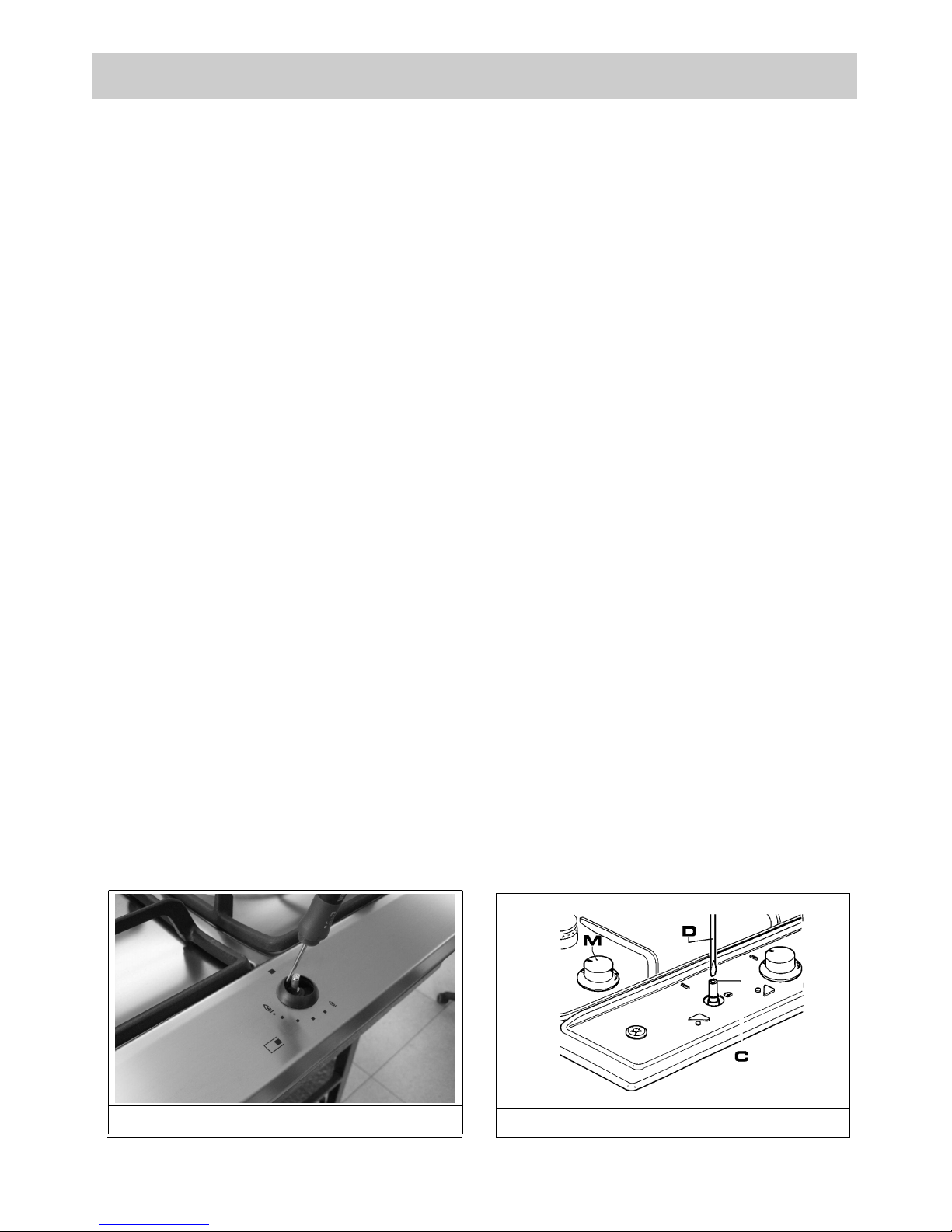
7) TAPS
Our taps are suitable for all gas, they are male
conical type.
“Reduced rate” adjustment
- Switch on the burner and turn the relative knob to
the “Reduced rate” position (small flame fig. 1).
- Remove knob “M” (fig. 14 and 14/A) of the tap,
which is simply pressed on to its rod. The by-pass
for minimal rate regulation can be: beside the tap
(fig. 14) or inside the shaft. In any case, to access
to regulation, it can be done trought the insertion
of a small screwdriver ‘’D’’ beside the tap (fig. 14)
or in the hole ‘’C’’ inside the shaft of the tap
(fig 14/A). Turn the throttle screw to the right or left
un til the burner flam e ha s been adequately
regulated to the “Reduced rate” position.
The flame should not be too low: the lowest small
flame should b e continuous and ste ady. Reassemble the several components.
It is understood that only burners operating
with Natural gas should be subjected to the
above mentioned adjustments. The screw must
be fully locked when the burners operate with
Liquid gas.
FIG. 14/A
FIG. 14
Page 10

CONVERSIONS
8) U-LPG TO NATURAL GAS CONVERSION
PROCEDURE
Appliance models: Gas stainless steel hotplate
models:
1. Remove each burner cap and burner skirt.
2. Remove the U-LPG main injector with a 7
mm/VF t ube spa nner and rep lace wit h th e
appropriate size Natural Gas injector for each
burner. The following injector sizes are required for
Natural Gas:
Burner Main injector
Wok 1.76 mm
Rapid 1.55 mm
Semi Rapid 1.20 mm
Auxiliary 0.90 mm
3. Shut off gas supply to the appliance.
4. Disconnect gas inlet pipe from the U-LPG Gas
test point inlet fitting.
5. Remove the U-LPG test point inlet fitting from
the appliance.
6. Fit the Natural Gas Regulator supplied in the
conversion kit.
7. Connect the gas supply to the Regulator.
8. Check for gas leaks. Do not use a naked flame
to check for gas leaks.
9. Adjust the gas pressure to 1.00 kPa.
10. Remove the control knob, with a thin shaft blade
screwdriver down the centre of each gas valve
shaft, screw the by-pass injector anti-clockwise.
Test the appliance on both high and low flame for
each burner. If the burner fails to remain alight or
the flame is not stable on the simmer setting, adjust
the by-pass screw, until flame is stable.
11. If not already removed, remove the “Only for
use with U-LPG” label adhered to the bottom panel
near the gas connection.
9) NATURAL GAS TO UNIVERSAL
LPG CONVERSION PROCEDURE
Appliance models: Gas stainless steel hotplate
models:
1. Remove each burner cap and burner skirt.
2. Remove the Natural Gas main injector with a 7
mm /VF tube spanner and rep lace with the
appropriate size U-LPG main injector for each
burner. The following injector sizes are required for
U-LPG:
Burner Main injector
Wok 0.94 mm
Rapid 0.91 mm
Semi Rapid 0.70 mm
Auxiliary 0.53 mm
3. Remove the control knob, with a thin shaft blade
screwdriver down the centre of each gas valve
shaft, screw the by-pass injector fully clockwise.
4. Shut off gas supply to the appliance.
5. Disconnect gas inlet pipe from the Natural Gas
Regulator.
6. Remove the Natural Gas Regulator from the
appliance.
7. Fit the U-LPG test point inlet fitting supplied in
the conversion kit.
8. Connect the gas supply to the inlet fitting.
9. Check for gas leaks. Do not use a naked flame
to check for gas leaks.
10. Adjust the gas pressure to 2.75 kPa.
11. Test the appliance on both high and low flame
for each burner and check the gas pressure. If the
burner fails to remain alight or the flame is not
stable on the simmer setting, adjust the by-pass
screw, until flame is stable.
12. If not already removed, remove the “Only for
use with Natural Gas” label adhered to the bottom
panel near the gas connection.
10
Page 11
11
CONVERSIONS
10) REPLACING THE INJECTORS
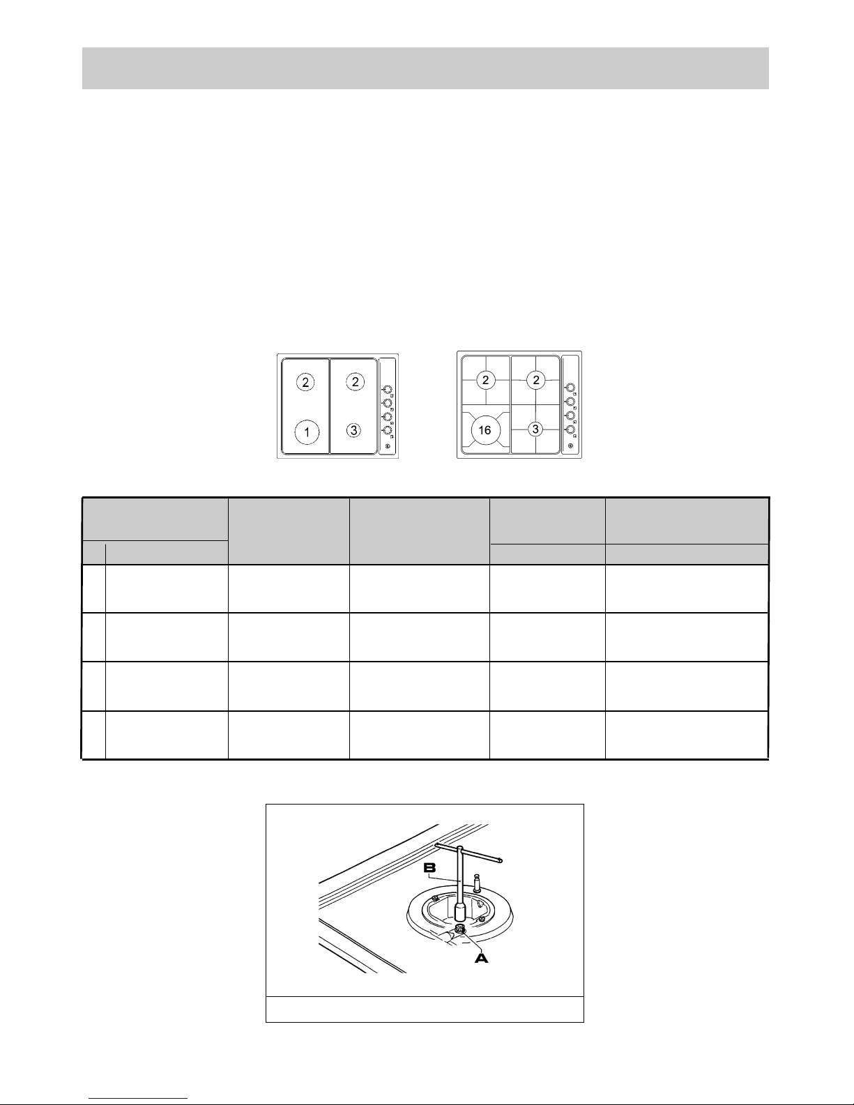
The burners can be adapted to different types of gas
by installing injectors suited to the type of gas
required. To do this, first remove the burner tops
using a wrench “B”. Now unscrew injector “A” (see
fig. 15) and fit a injector corresponding to the type of
gas required.
It is advisable to tighten the injector in place.
After the injectors have been replaced, the
burners must be regulated as explained in
paragraphs 7. The technician must reset any seals
on the regulating or pre-regulating devices and
affix the label corresponding to the new gas
regulation on the appliance instead of the already
existing one. This label is supplied in the packet
containing the spare injectors.
The envelope with the injectors and the labels can
be included in the kit, or at disposal to the
authorised customer Service Centre.
For the sake of convenience, the nominal rate chart
also lists the heat inputs of the burners, the diameter
of the injectors and the working pressures of the
various types of gas.
BURNER ARRANGEMENT ON THE HOT PLATE
1 RAPID
U-LPG 2.75 91 10.4
NATURAL 1.00 155 12.0
2 SEMI-RAPID
U-LPG 2.75 70 6.2
NATURAL 1.00 120 7.1
3 AUXILIARY
U-LPG 2.75 50 3.5
NATURAL 1.00 90 4.1
16 ULTRA RAPID
U-LPG 2.75 94 11.4
NATURAL 1.00 176 14.5
TABLE 1
BURNERS
N° DESCRIPTION
GAS
NORMAL
PRESSURE
INJECTOR
DIAMETER
NOMINAL
HEAT INPUT (MJ/h)
(kPa) (1/100 mm) MAX.
FIG. 15
Page 12
12
SERVICING
Always turn off the electrical ignition before
proceeding with any servicing operation.
Servic ing should be carrie d out only by
authorised personnel.
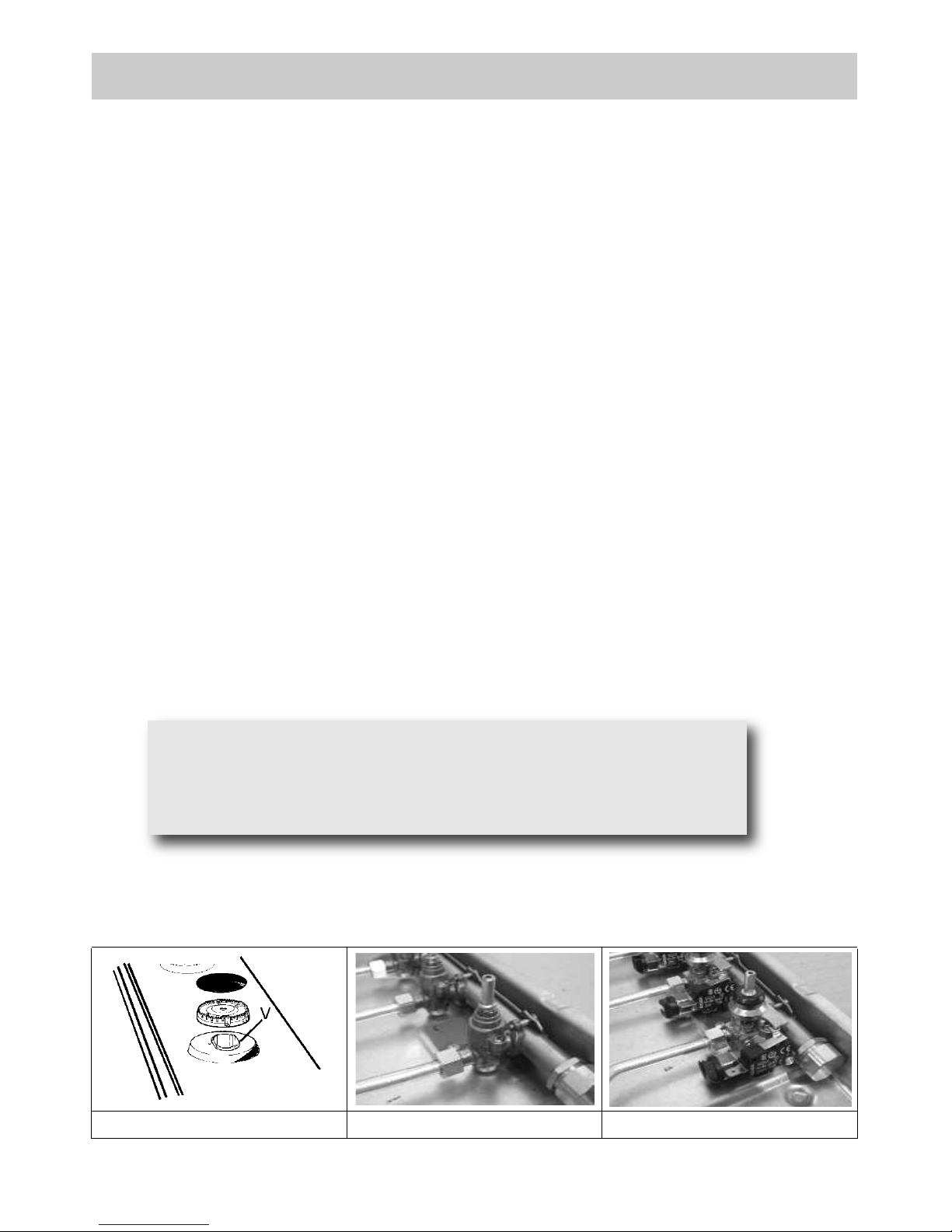
11) REPLACING HOT PLATE PARTS
To replace the components fitted inside the hob,
take off the knobs, all the movable parts of the hobs
(trivets, burners and caps) and the screws “V” on
the burners (see fig. 16).
After having carried out the above listed operations,
the replacement of the electrical components and
the taps is possible.
REMARKS: before replacing the taps on the hob
withou t flame fai lure devi ce, take off the
microswitches fitted on the taps.
It is advisable to change seal “D” whenever a tap is
replaced to ensure a perfect tightness.
Greasing the taps (see fig. 17 - 18)
If a ta p bec omes stiff to ope rate, it must be
immediate ly gre ase d in com pli ance with the
following instructions:
- remove the tap.
- Clean the cone and its housing using a cloth
soaked in solvent.
- Lightly spread the cone with the relevant grease.
- Fit the cone back in place, operate it several times
and then remove it again. Eliminate any excess
grease and check that the gas ducts have not
become clogged.
- Fit all parts back in place, complying with the
demounting order in reverse.
- The tight closure test must be done using a foamy
liquid.
To facilitate the servicing technician’s task, here is a
chart with the types and sections of the powering
cables and the ratings of the electrical components.
FIG. 16 FIG. 17 FIG. 18
WARNING:
MAINTENANCE MUST ONLY BE PERFORMED
BY AUTHORISED PERSONS.
Page 13
13
SERVICING
TYPE OF TYPE OF SINGLE - PHASE
HOT PLATE CABLE POWER SUPPLY
CABLE TYPES AND SECTIONS
ATTENTION!!!
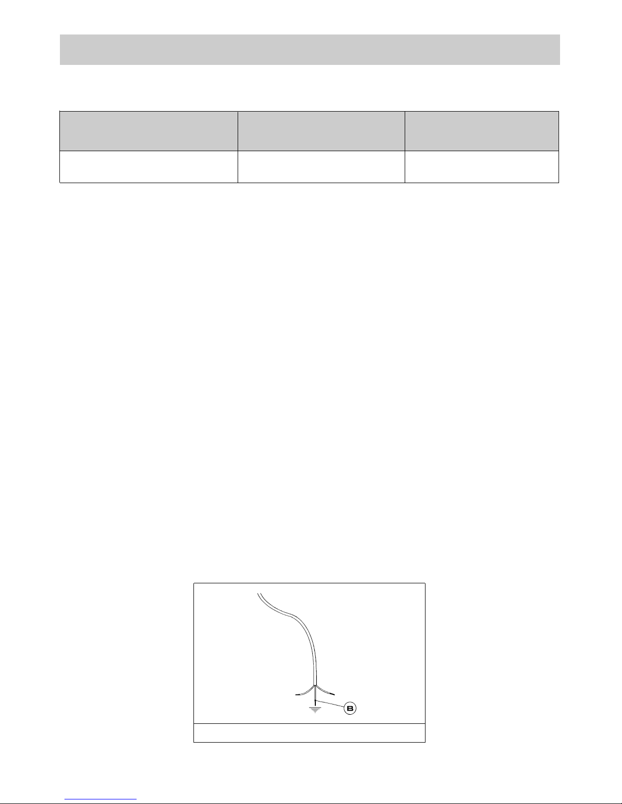
If the power supply cable is replaced, the installer should leave the ground wire longer than the phase
conductors (fig. 19) and comply with the recommendations given in paragraph 6.
FIG. 19
H05 RR - F Section 3 X 0.75 mm
2
Gas hot plate
Page 14

TECHNICAL ASSISTANCE AND SPARE PARTS
14
Before leaving the factory, this appliance will have been tested and regulated by expert and specialized
personnel in order to guarantee the best performances.
Any repairs or adjustments which may be subsequently required may only be carried out by qualified
personnel with the utmost care and attention.
For this reason, always contact your Dealer or our nearest After Sales Service Center whenever repairs or
adjustments are required, specifying the type of fault and the model of the appliance in your possession.
Please also note that genuine spare parts are only available from our After Sales Service Centers and
authorized retail outlets.
The above data are printed on the data label put on the inferior part of the appliance and on the packing
label.
The above informations give to the technical assistant the possibility to get fit spare parts and a heaven-sent
intervention. We suggest to fill the table below.
MARK: ........................................................
MODEL: .....................................................
SERIES: .....................................................
Page 15

15
Page 16

16
 Loading...